Loading ...
Loading ...
Loading ...
43
ENGLISH
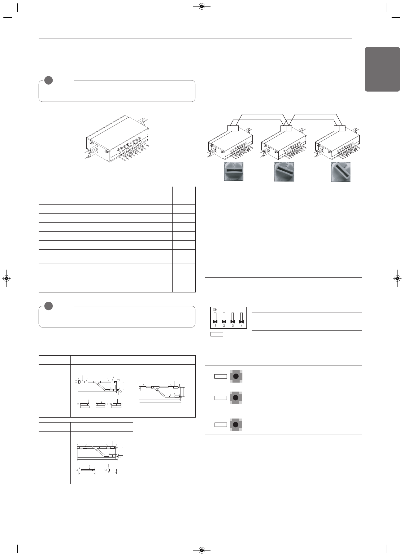
3 Series
Main function of SW01D
- Selection of the Valve Group Control
NOTE
!
Use the Valve Group Control when 2 branches are connected with
only 1 indoor unit which has higher capacity than 61 kBtu.
NOTE
!
If the large capacity indoor units are installed, below Y branch pipe
should be used.
Valve Group
SW01D
Setting
Valve Group
SW01D
Setting
Not control 0 No. 5,6/7,8 Valve Control 8
No. 1,2 Valve Control 1 No. 1,2/5,6 Valve Control 9
No. 2,3 Valve Control 2 No. 1,2/7,8 Valve Control A
No. 3,4 Valve Control 3 No. 3,4/5,6 Valve Control B
No. 5,6 Valve Control 4 No. 3,4/7,8 Valve Control C
No. 6,7 Valve Control 5
No. 1,2/3,4/5,6 Valve
Control
D
No. 7,8 Valve Control 6
No. 1,2/3,4/6,7 Valve
Control
E
No. 1,2/3,4 Valve
Control
7
No. 1,2/3,4/7,8 Valve
Control
F
* Master Only
Models Low Pressure Gas Pipe Liquid pipe
ARBLB03321
413(16-1/4)
390(15-11/32)
I.D19.05(3/4)
I.D19.05(3/4)
I.D19.05(3/4)
I.D12.7(1/2)
I.D12.7
(1/2)
70(2-3/4)
I.D15.88(5/8)
I.D15.88(5/8)
I.D25.4(1)
I.D25.4(1)
O.D25.4(1)
80(3-5/32)
110(4-11/32)
83
(3-9/32)
1
2
3
3
O.D19.05(3/4)
O.D19.05(3/4)
1
2
I.D22.2(7/8)
I.D22.2(7/8)
I.D22.2(7/8)
I.D28.58(1-1/8)
I.D12.7(1/2)
I.D12.7(1/2)
I.D12.7(1/2)
74
(2-29/32)
332(13-1/16)
321(12-5/8)
I.D6.35(1/4)
I.D6.35
(1/4)
I.D9.52(3/8)
I.D9.52(3/8)
I.D9.52(3/8)
Models High Pressure Gas Pipe
ARBLB03321
I.D15.88(5/8)
I.D12.7(1/2)
I.D12.7(1/2)
70(2-3/4)
I.D25.4(1)
110(4-11/32)
I.D19.05(3/4)
I.D19.05(3/4)
2
3 2
3
O.D15.88(5/8)
444(17-15/32)
421(16-9/16)
96
(3-25/32)
I.D15.88
(5/8)
I.D22.2(7/8)
I.D22.2(7/8)
I.D22.2(7/8)
O.D15.88(5/8)
I.D19.05(3/4)
I.D9.52(3/8)
h Y branch pipe
[Unit : mm(inch)]
SW01C (Rotary S/W for addressing HR unit)
Must be set to '0' when installing only one HR unit.
When installing multiple HR units, address the HR units with
sequentially increasing numbers starting from '0'.
Maximum 16 HR Units can be installed.
Ex) Installation of 3 HR units
SW01B/SW01C/SW01E/SW02B
(DIP S/W and push S/W for Manual pipe detection)
- Set the address of the valve of the HR unit to the central control
address of the connected indoor unit.
- SW01E: selection of the valve to address
SW02B: increase in the digit of 10 of valve address
SW01B: increase in the last digit of valve address
SW01C: Manual addressing of zoning indoor units
(use for Zoning setting)
- Prerequisite for Manual pipe detection : central control address of
each indoor unit must be preset differently at its wired remote
control.
AB AB AB
* Master Only
SW01E
S/W No. Setup
No.1
Manual addressing of valve #1
(Master) / #5 (Slave)
No.2
Manual addressing of valve #2
(Master) / #6 (Slave)
No.3
Manual addressing of valve #3
(Master) / #7 (Slave)
No.4
Manual addressing of valve #4
(Master) / #8 (Slave)
SW02B
SW02B
Increase in the digit of 10 of valve
address
SW01B
SW01B
Increase in the last digit of valve
address
SW01B
SW01C
Manual addressing of zoning indoor
units
* Use for Zoning setting
1,MFL68980308,영영 2018. 11. 13. 영영 3:24 Page 43
Loading ...
Loading ...
Loading ...