Loading ...
Loading ...
Loading ...
Installation Instructions
FINAL INSTALLATION CHECKLIST
• Check to make sure the circuit breaker is closed (RESET) or
the circuit fuses are replaced.
• Be sure power is in service to the building.
• Note (on some models): If the clock flashes “bAd” and then “LinE”
with a loud tone, the neutral connection to the range is not wired
correctly. Check the terminal block connections and/or house
wiring to correct.
• Check to be sure that all packing materials and tape have been
removed. This will include tape on metal panel under control
knobs (if applicable), adhesive tape, wire ties, cardboard and
protective plastic. Failure to remove these materials could result
in damage to the appliance once the appliance has been turned
on and surfaces have heated.
• Check to make sure that the rear leveling leg is fully inserted into
the Anti-Tip bracket and that the bracket is securely installed.
5
OPERATION CHECKLIST
• Turn on one of the surface units to observe that the element
glows within 60 seconds. Turn the unit off when glow is detected.
If the glow is not detected within the time limit, recheck the range
wiring connections. If change is required, retest again. If no
change is required, have building wiring checked for proper
connections and voltage.
• Check to make sure the Clock (on models so equipped) display is
energized. If a series of horizontal red lines appear in the display,
disconnect power immediately. Recheck the range wiring
connections. If change is made to connections, retest again.
If no change is required, have building wiring checked for proper
connections and voltage. It is recommended that the clock be
changed if the red lines appear.
• Be sure all range controls are in the OFF position before leaving
the range.
6
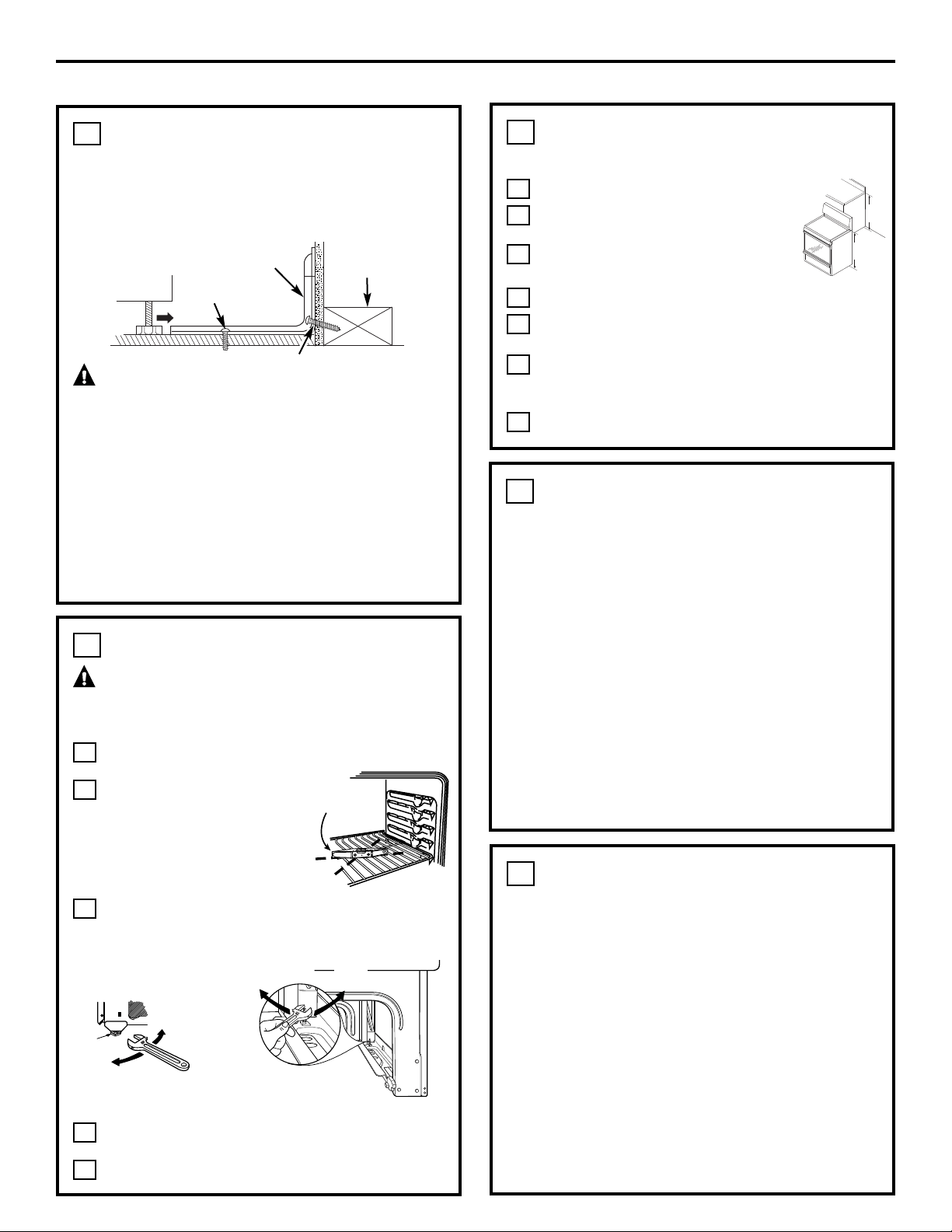
LEVEL THE RANGE
WARNING:Never completely remove the leveling leg
as the range will not be secured to the anti-tip device properly.
MODELS WITHOUT BAKING OR WARMING DRAWERS
Install the oven racks in the oven and position the range
where it will be installed.
Check for levelness by placing a
spirit level or a cup, partially filled
with water, on one of the oven
racks. If using a spirit level, take two
readings—with the level placed
diagonally first in one direction and
then the other.
Remove the storage drawer, broiler drawer or kick panel.
The front leveling legs can be adjusted from the bottom
and the rear legs can be adjusted from the top.
Use an open-end or adjustable wrench to adjust
the leveling legs until the range is level.
Replace the drawer or panel.
E
D
C
B
A
4
LEVEL THE RANGE (cont.)
MODELS WITH BAKING OR WARMING DRAWERS
Plug in the range.
Measure the height of your countertop at
the rear of the opening (X).
Adjust two rear leveling legs so that the rear of
cooktop is at the same height as the counter (Y).
Slide unit into place.
Install oven racks in the oven and position the range where
it will be installed.
Check for levelness by placing a spirit level on one of
the oven racks. Take two readings—with the level placed
diagonally first in one direction and then the other.
Adjust front leveling legs until the range is level.
G
F
E
D
C
B
A
4
Spirit level
42
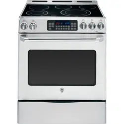
ANTI-TIP DEVICE INSTALLATION
An Anti-Tip bracket is supplied with instructions for installation in a
variety of locations. The instructions include all necessary information
to complete the installation. Read the Safety Instructions and the
instructions that fit your situation before beginning installation.
WARNING:
• Range must be secured with an approved Anti-Tip device.
• Unless properly installed, the range could be tipped by you
or a child standing, sitting or leaning on an open door.
• After installing the Anti-Tip device, verify that it is in place
by carefully attempting to tilt the range forward.
• This range has been designed to meet all recognized industry
tip standards for all normal conditions.
• The use of this device does not preclude tipping of the range
when not properly installed.
• If the Anti-Tip device supplied with the range does not fit this
application, use the universal Anti-Tip device WB02K10254.
3
Screw must enter
wood or concrete
Attachment to Wall or Floor
Wall Sill Plate
Screw must enter wood
Bracket
X
Y
Rear leveling legs
(on some models)
Front leveling legs
(on some models)
Lower
range
Raise
range
Adjust
from
the top
Front of range
Leg
leveler
Lower
range
Raise range
Adjust from
the bottom
Loading ...
Loading ...
Loading ...