Loading ...
Loading ...
Loading ...
22 23INSTALLING THE GAS ELEVATED COOKERINSTALLING THE ELECTRIC ELEVATED COOKER
• In order to avoid overheating of the cooker,
the cooker must not be installed behind a
decorative door.
• The appliance MUST be installed using the
flexible hose supplied.
• The vents, openings and air spaces MUST NOT
be blocked.
• You MUST NOT pull the cooker by the door
handles or the splashback.
• The cooker MUST be checked every five years.
• The cooker MUST NOT be used as a space heater.
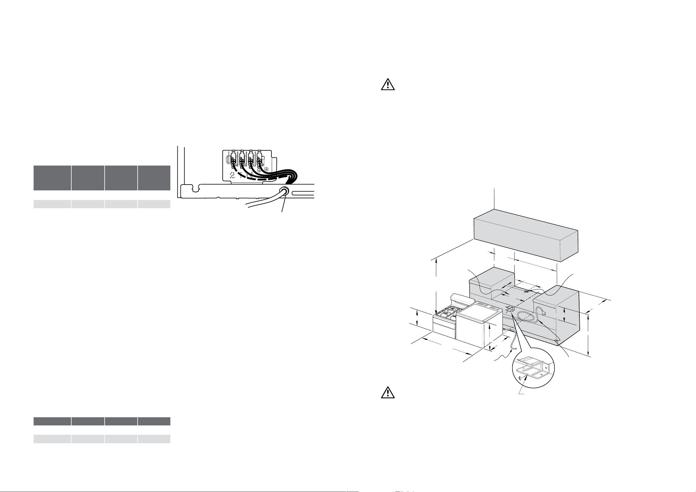
Locating the cooker
Study the diagrams below to be sure of the dimensions
required to locate the cooker safely.
INSTALLING THE GAS ELEVATED COOKER
Safety Warnings about installation
WARNING
WARNING
• The cooker MUST be installed and serviced by a
qualified technician.
• A Certificate of Compliance MUST be supplied to
be kept by the customer.
• The packing materials MUST be removed before
you install the cooker.
• You MUST follow the installation instructions in
this booklet.
• The surrounding kitchen cabinets MUST be able
to withstand 85°C. Electrolux Products WILL
NOT accept responsibility for damage caused
by installation into kitchen cabinets which cannot
withstand 85°C.
Hard wiring
1. To gain access to the terminal block, remove the
small rear panel by unscrewing the two screws.
2. Fit wires through the hole in the base using the
appropriate gland to protect insulation of wires
from the hole edge.
3. Set the length of wiring from the gland to terminal
block, ensuring length is sufficient but not excessive.
4. Make connections to terminals.
5. Replace rear panel.
A2
A1
N
INSTALLING THE ELECTRIC ELEVATED COOKER
Electric wiring requirements
The cooker MUST be installed in compliance with:
• Wiring connections in AS/NZS3000 wiring rules.
• Local regulations, municipal building codes and other
statutory regulations.
• Data plate – Gives information about the rating and
is located behind the bottom of the oven door.
For New Zealand only: The cooking range must be
connected to the supply by a supply cord fitted with
the appropriately rated plug that is compatible with the
socket-outlet fitted to the final sub-circuit in the fixed
wiring that is intended to supply this cooking range.
See table below:
MODEL
CURRENT
RATING
(AMPS)
WIRE
SECTION
(MM2)
MINIMUM
TEMP
RATING
(°C)
WDE135WA 50 6 75
WDE147WA 50 6 75
• A functional switch MUST be provided near the
appliance in an accessible position (AS/NZS3000 –
Clause 4.7.1).
• Wiring MUST be protected against mechanical failure
(AS/NZS3000 – Clause 3.9).
• The cooker requires a means of all pole disconnection
incorporated into the fixed wiring. This MUST have a
disconnection gap of 3mm.
• The cooker MUST be properly earthed.
• This product has passed the insulation resistance
test after manufacture. If the resistance reading is low
at installation, it is probably caused by moisture from
the atmosphere being absorbed by the elements
after the range has been produced. (Pass at 0.01MΩ
AS/NZS 3000 Wiring Rules Clause 8.3.6.2)
• When connections are made to a multiphase
230/240V supply, the bridge piece MUST be removed
from between the active connections.
• If the supply cord is damaged, it must be replaced
by the manufacturer, its service agent or similarly
qualified persons in order to avoid a hazard.
IMPORTANT: Before you cook in your new oven
it is important that the protective oils used in the
manufacture of the product be removed. Refer to
‘Before Operating your Appliance for the First Time’
in the Using The Oven section.
300 Maximum
600
Locating V
900
1095 Minimum
280 R.H. Oven
720 L.H. Oven
1.7m
Gas supply hose
2.0m
Electrical service
cord (if fitted)
50mm diameter access
hole to gas supply and
power point (if required)
1085
320
500 minimum
to combustible
material
40
762
520
620
120
minimum
to
combustible
material
Dimension to centre
line of anti-tilt plate
WARNING
WARNING
In order to avoid accidental tipping of the appliance (for
example, by a child climbing onto the open oven door),
the anti-tilt plate MUST be installed.
Position the anti-tilt plate to the rear wall and 762mm
from the left side of the wall. Dimension to the “v” at
the front of the anti-tilt plate and then securely fix
with fasteners.
MODEL TOTAL kW A1 kW A2 kW
WDE135WA 10.1 4.1 6.0
WDE147WA 10.5 4.1 6.4
Rated power input
Gland
Loading ...
Loading ...
Loading ...