Loading ...
Loading ...
Loading ...
7
English
Fig. D
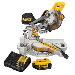
Bench Mounting (Fig. A)
Holes
3
are provided in all 4 feet to facilitate bench mounting, as shown in FigureA. (Two
different-sized holes are provided to accommodate different sizes of screws. Use either hole,
it is not necessary to use both.) Always mount your saw firmly to a stable surface to prevent
movement. To enhance the tool’s portability, it can be mounted to a piece of 1/2" (12.7 mm) or
thicker plywood which can then be clamped to your work support or moved to other job sites
andreclamped.
nOTE: If you elect to mount your saw to a piece of plywood, make sure that the mounting
screws don’t protrude from the bottom of the wood. The plywood must sit flush on the work
support. When clamping the saw to any work surface, clamp only on the clamping bosses where
the mounting screw holes are located. Clamping at any other point will interfere with the proper
operation of thesaw.
CAUTION: To prevent binding and inaccuracy, be sure the mounting surface is not warped
or otherwise uneven. If the saw rocks on the surface, place a thin piece of material under one
saw foot until the saw sits firmly on the mountingsurface.
COMPONENTS (FIG. A)
WARNING: Never modify the power tool or any part of it. Damage or personal injury
couldresult.
Refer to Figure A at the beginning of this manual for a complete list ofcomponents.
INTENDED USE
This heavy duty miter saw is designed for professional wood cuttingapplications.
DO nOT use under wet conditions or in presence of flammable liquids orgases.
This miter saw is a professional power tool. DO nOT let children come into contact with the tool.
Supervision is required when inexperienced operators use thistool.
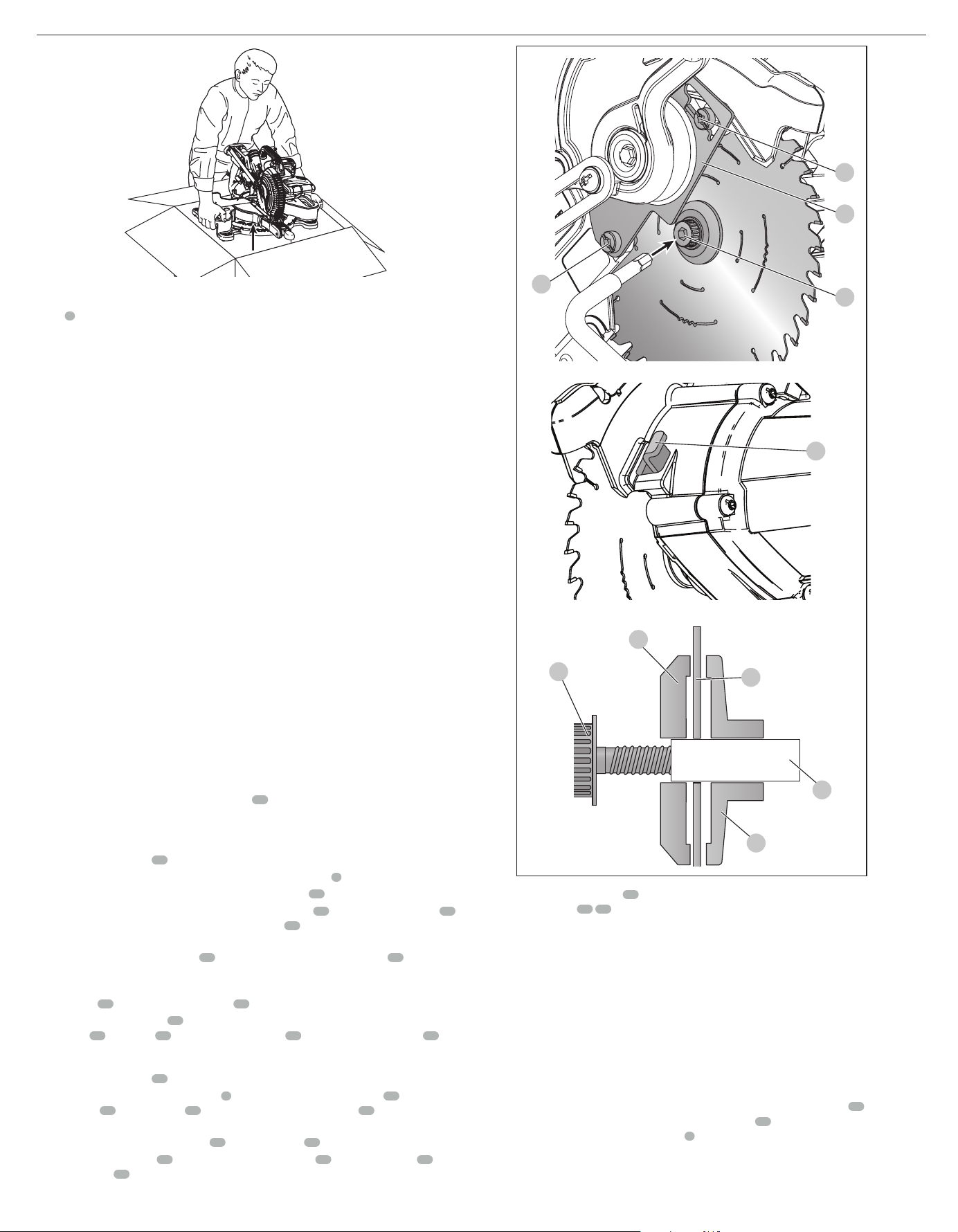
Changing or Installing a New Saw Blade (Fig. E)
Refer to Saw Blades under Optional Accessories for correct sawblade.
WARNING: To reduce the risk of serious personal injury, turn tool off and remove the
battery pack before transporting, making any adjustments or removing/installing
attachments or accessories. An accidental start-up can causeinjury.
CAUTION:
• Never depress the spindle lock button
32
while the blade is under power orcoasting.
• Do not cut metal, masonry or fiber cement product with this mitersaw.
Removing the Blade (Fig. A, E)
1. Remove battery pack
16
from thesaw.
2. Raise the arm to the upper position and raise the lower guard
4
as far aspossible.
3. Loosen, but do not remove the guard bracket rear screw
25
by fourrevolutions.
4. Loosen, but do not remove the guard bracket front screw
24
(Fig.E) until the bracket
26
can be raised far enough to access the blade screw
28
. Lower guard will remain raised due
to the position of the guard bracketscrew.
5. Depress the spindle lock button
32
while carefully rotating the saw blade
27
by hand until
the lockengages.
6. Keeping the button depressed, use the other hand and the 1/4" hex side of the wrench
provided
22
to loosen the blade screw
28
. (Turn clockwise, left-hand threads.)
7. Remove the blade screw
28
using the 1/4" hex side of the wrench provided, the outer clamp
washer
29
and blade
27
. The inner clamp washer
30
may be left on the spindle
31
.
Installing a Blade (Fig. A, E)
1. Remove battery pack
16
from thesaw.
2. With the arm raised, the lower guard
4
held open and the guard bracket
26
raised, place
the blade
27
on the spindle
31
and against the inner blade clamp
30
with the teeth on the
blade pointing in the direction of rotation as marked on thesaw.
3. Assemble the outer clamp washer
29
onto the spindle
31
.
4. Install the blade screw
28
and, engaging the spindle lock
32
, tighten the screw
28
firmly
with wrench
22
provided (turn counterclockwise, left-hand threads).
5. Return the guard bracket
26
to its original full down position and firmly tighten both guard
bracket screws
24
25
to hold bracket inplace.
WARNING: The guard bracket must be returned to its original full down position
and the guard bracket screws tightened before activating the saw. Failure to do so
may prevent the guard from closing or may allow the guard to contact the spinning
saw blade resulting in damage to the saw and severe personalinjury.
Transporting the Saw (Fig. A)
WARNING: To reduce the risk of serious personal injury, turn tool off and remove the
battery pack before transporting, making any adjustments or removing/installing
attachments or accessories. An accidental start-up can causeinjury.
WARNING: To reduce the risk of serious personal injury, ALWAYS lock the rail lock
knob, miter lock handle, bevel lock handle and lock down pin, and remove the battery before
transportingsaw.
In order to conveniently carry the miter saw from place to place, a lifting handle
15
has been
included on the top of the saw arm and hand indentations
10
in the base, as shown in FigureA.
Do not lift or carry by the operating handle
2
.
Fig. E
24
26
28
25
32
29
27
28
31
30
Loading ...
Loading ...
Loading ...