Loading ...
Loading ...
Loading ...
10
English
Clamping the Workpiece
WARNING: To reduce the risk of serious personal injury, turn tool off and remove the
battery pack before transporting, making any adjustments or removing/installing
attachments or accessories. An accidental start-up can causeinjury.
WARNING: A workpiece that is clamped, balanced and secure before a cut may become
unbalanced after a cut is completed. An unbalanced load may tip the saw or anything the
saw is attached to, such as a table or workbench. When making a cut that may become
unbalanced, properly support the workpiece and ensure the saw is firmly bolted to a stable
surface. Personal injury mayoccur.
WARNING: The clamp foot must remain clamped above the base of the saw whenever the
clamp is used. Always clamp the workpiece to the base of the saw – not to any other part of
the work area. Ensure the clamp foot is not clamped on the edge of the base of thesaw.
WARNING: Always use a work clamp to maintain control and reduce the risk of workpiece
damage and personal injury, if your hands are required to be within 4" (100 mm) of the blade
during thecut.
If you cannot secure the workpiece on the table and against the fence by hand (irregular shape,
etc.), or your hand would be less than 4" (100 mm) from the blade, a clamp or other fixture must
beused.
Use the material clamp provided with your saw. To purchase a material clamp, contact your local
retailer or
DeWALT
servicecenter.
Other aids such as spring clamps, bar clamps or C-clamps may be appropriate for certain sizes
and shapes of material. Use care in selecting and placing these clamps. Take time to make a dry
run before making thecut.
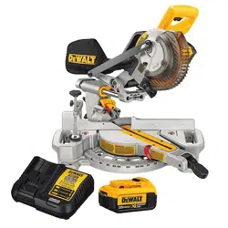
To Install Clamp (Fig. A, M)
1. Insert the clamp
44
into the hole
21
behind the fence. The clamp should be facing toward
the back of the miter saw. The groove on the clamp rod should be fully inserted into the base.
Ensure this groove is fully inserted into the base of the miter saw. If the groove is visible, the
clamp will not besecure.
Fig. M
44
21
2. Rotate the clamp 180º toward the front of the mitersaw.
3. Loosen the knob to adjust the clamp up or down, then use the fine adjust knob to firmly
clamp theworkpiece.
nOTE: Place the clamp on the opposite side of the base when beveling. ALWAYS MAKE DRY
RUNS (UNPOWERED) BEFORE FINISH CUTS TO CHECK THE PATH OF THE BLADE. ENSURE THE
CLAMP DOES NOT INTERFERE WITH THE ACTION OF THE SAW ORGUARDS.
ADJUSTMENTS
WARNING: To reduce the risk of serious personal injury, turn tool off and remove the
battery pack before transporting, making any adjustments or removing/installing
attachments or accessories. An accidental start-up can causeinjury.
Your miter saw is fully and accurately adjusted at the factory at the time of manufacture.
If readjustment due to shipping and handling or any other reason is required, follow the
instructions below to adjust yoursaw.
Once made, these adjustments should remain accurate. Take a little time now to follow these
directions carefully to maintain the accuracy of which your saw iscapable.
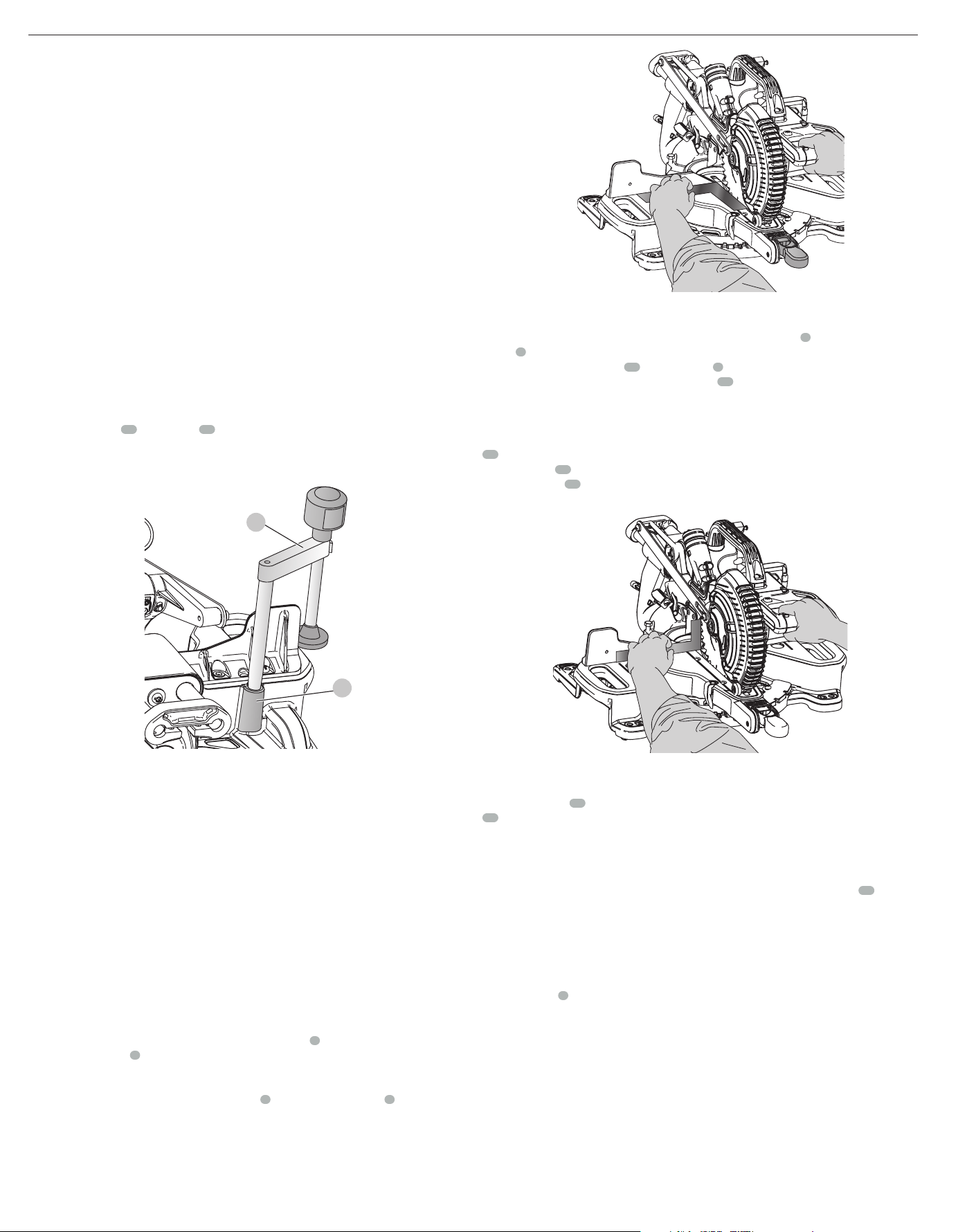
Miter Scale Adjustment (Fig. F, N)
Lock the arm in the down position. Unlock the miter lock knob
5
and swing the miter arm until
the miter latch button
6
locks it at the 0° miter position. Do not lock the miter lock knob. Place
a square against the saw’s fence and blade, as shown. (Do not touch the tips of the blade teeth
with the square. To do so will cause an inaccurate measure ment.) If the saw blade is not exactly
perpendicular to the fence, loosen the three screws
9
that hold the miter scale
8
and move
the miter lock handle and the scale left or right until the blade is perpendicular to the fence, as
measured with the square. Retighten the three screws. Pay no attention to the reading of the
miter pointer at thistime.
Fig. N
Miter Pointer Adjustment (Fig. F)
Unlock the miter lock mechanism by pulling up on the miter lock knob
5
. Push the miter latch
button
6
down and allow the miter latch to snap into place as you rotate the miter arm to
zero. Observe the miter pointer
33
and miter scale
8
shown in FigureE. If the pointer does not
indicate exactly zero, loosen the miter pointer screw
34
holding the pointer in place, reposition
the pointer and tighten thescrew.
Bevel Square to Table Adjustment (Fig. A, G, O)
To align the blade square to the table, lock the arm in the down position with the lock down pin
23
. Place a square against the blade, ensuring the square is not on top of a tooth. Loosen the
bevel lock knob
12
and ensure the arm is firmly against the 0° bevel stop. Rotate the 0° bevel
adjustment screw
45
with the 1/2" (12.7 mm) socket (not provided) as necessary so that the
blade is at 0° bevel to the table, as measured with thesquare.
Fig. O
Bevel Pointer (Fig. G)
If the bevel pointer
39
does not indicate zero, loosen the screw that holds the bevel pointer
41
in place and move it as necessary. Ensure the 0° bevel is correct and the bevel pointer is set
before adjusting any other bevel anglescrews.
Bevel Stop 45º Left Adjustment (Fig. A, G)
To adjust the left 45° bevel stop, first loosen the bevel lock knob and tilt the head to the left. If the
bevel pointer does not indicate exactly 45°, turn the left 45° bevel adjustment screw
46
until the
bevel pointer reads 45°.
Guard Actuation and Visibility (Fig. A, W)
CAUTION: Pinch hazard. To reduce the risk of injury, keep thumb underneath the operating
handle when pulling the handle down. The lower guard will move up as the operating
handle is pulled down, which could causepinching.
The lower guard
4
on your saw has been designed to automatically uncover the blade when the
arm is brought down and to cover the blade when the arm israised.
Before each use or after making adjustments, cycle the arm (unpowered) and make sure the
guard opens smoothly and closes fully. It should not contact the blade. With the arm up, raise the
guard (unpowered) as shown in FigureW and release. The guard should fully close rapidly. Do
not operate the saw if the guard does not move freely and fully close rapidly. Never clamp or tie
the guard in an open position when operating thesaw.
The guard can be raised by hand when installing or removing saw blades or for inspection of the
saw. NEVER RAISE THE lower GUARD MANUALLY UN LESS THE BLADE ISSTOPPED.
nOTE: Certain special cuts of large material will require that you manually raise the guard. Refer
to Cutting large Material under SpecialCuts.
Loading ...
Loading ...
Loading ...