
Loading ...
Loading ...
Loading ...
6
English
3. The completion of charge will be indicated by the red light remaining ON continuously. The
battery pack is fully charged and may be used at this time or left in the charger. To remove
the battery pack from the charger, push the battery release button
40
on the batterypack.
nOTE: To ensure maximum performance and life of lithium-ion battery packs, charge the battery
pack fully before firstuse.
Charger Operation
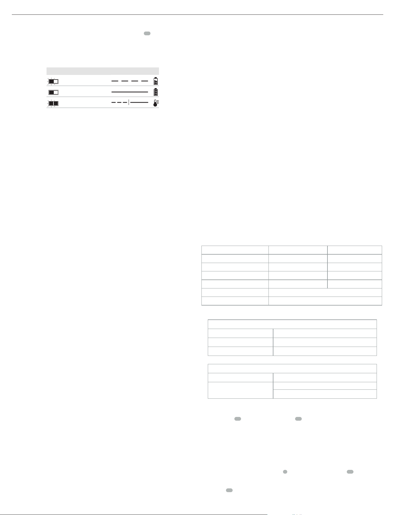
Refer to the indicators below for the charge status of the batterypack.
DCB107, DCB112, DCB113, DCB115, DCB118, DCB132
Charging
Fully Charged
Hot/Cold Pack Delay*
* DCB107, DCB112, DCB113, DCB115, DCB118, DCB132: The red light will continue to blink,
but a yellow indicator light will be illuminated during this operation. Once the battery pack has
reached an appropriate temperature, the yellow light will turn off and the charger will resume
the chargingprocedure.
The compatible charger(s) will not charge a faulty battery pack. The charger will indicate faulty
battery pack by refusing to light or by displaying a problem pack or charger blinkpattern.
nOTE: This could also mean a problem with acharger.
If the charger indicates a problem, take the charger and battery pack to be tested at an
authorized servicecenter.
hot/Cold Pack Delay
When the charger detects a battery pack that is too hot or too cold, it automatically starts a
Hot/Cold Pack Delay, suspending charging until the battery pack has reached an appropriate
temperature. The charger then automatically switches to the pack charging mode. This feature
ensures maximum battery packlife.
A cold battery pack will charge at a slower rate than a warm battery pack. The battery pack will
charge at that slower rate throughout the entire charging cycle and will not return to maximum
charge rate even if the battery packwarms.
The DCB118 charger is equipped with an internal fan designed to cool the battery pack. The fan
will turn on automatically when the battery pack needs to becooled.
Never operate the charger if the fan does not operate properly or if ventilation slots are blocked.
Do not permit foreign objects to enter the interior of thecharger.
Electronic Protection System
Li-Ion tools are designed with an Electronic Protection System that will protect the battery pack
against overloading, overheating or deepdischarge.
The tool will automatically turn off if the Electronic Protection System engages. If this occurs,
place the lithium-ion battery pack on the charger until it is fullycharged.
Wall Mounting
DCB107, DCB112, DCB113, DCB115, DCB118, DCB132
These chargers are designed to be wall mountable or to sit upright on a table or work surface. If
wall mounting, locate the charger within reach of an electrical outlet, and away from a corner or
other obstructions which may impede air flow. Use the back of the charger as a template for the
location of the mounting screws on the wall. Mount the charger securely using drywall screws
(purchased separately) at least 1" (25.4 mm) long, with a screw head diameter of 0.28–0.35"
(7–9mm), screwed into wood to an optimal depth leaving approximately 7/32" (5.5 mm) of
the screw exposed. Align the slots on the back of the charger with the exposed screws and fully
engage them in theslots.
Charger Cleaning Instructions
WARNING: Shock hazard. Disconnect the charger from the AC outlet before cleaning. Dirt
and grease may be removed from the exterior of the charger using a cloth or soft non-
metallic brush. Do not use water or any cleaningsolutions.
Important Charging Notes
1. Longest life and best performance can be obtained if the battery pack is charged when the
air temperature is between 65°F and 75°F (18° – 24°C). DO NOT charge the battery pack in
an air temperature below +40°F (+4.5°C), or above +104°F (+40°C). This is important and
will prevent serious damage to the batterypack.
2. The charger and battery pack may become warm to the touch while charging. This is a
normal condition, and does not indicate a problem. To facilitate the cooling of the battery
pack after use, avoid placing the charger or battery pack in a warm environment such as in a
metal shed or an uninsulatedtrailer.
3. If the battery pack does not charge properly:
a. Check operation of receptacle by plugging in a lamp or other appliance;
b. Check to see if receptacle is connected to a light switch which turns power off when you
turn out the lights;
c. Move the charger and battery pack to a location where the surrounding air temperature is
approximately 65°F – 75°F (18° – 24°C);
d. If charging problems persist, take the tool, battery pack and charger to your local
servicecenter.
4. The battery pack should be recharged when it fails to produce sufficient power on jobs which
were easily done previously. DO NOT CONTINUE to use under these conditions. Follow the
charging procedure. You may also charge a partially used pack whenever you desire with no
adverse effect on the batterypack.
5. Foreign materials of a conductive nature such as, but not limited to, grinding dust, metal
chips, steel wool, aluminum foil, or any buildup of metallic particles should be kept away
from charger cavities. Always unplug the charger from the power supply when there is no
battery pack in the cavity. Unplug the charger before attempting toclean.
6. Do not freeze or immerse the charger in water or any otherliquid.
Storage Recommendations
1. The best storage place is one that is cool and dry, away from direct sunlight and excess heat
orcold.
2. For long storage, it is recommended to store a fully charged battery pack in a cool dry place
out of the charger for optimalresults.
nOTE: Battery packs should not be stored completely depleted of charge. The battery pack will
need to be recharged beforeuse.
SAVE THESE INSTRUCTIONS FOR
FUTURE USE
Unpacking Your Saw
Check the contents of your miter saw carton to make sure that you have received allparts.
In addition to this instruction manual, the carton should contain:
1 DCS361 miter saw
1
DeWALT
7–1/4" (184 mm) diameter saw blade
1 1/4" (6.35 mm) hex and T30 torx blade wrench
1 Charger (Kit only)
1 Battery (Kit only)
In bag:
1 Dust bag
1 Material clamp
Specifications
Capacity of cut
height Width
0º Miter / 0º Bevel 2" (50.8mm) 8" (209.5 mm)
45º Meter / 0º Bevel 2" (50.8mm) 5.75" (146 mm)
48º Miter / 0º Bevel 2" (50.8mm) 6" (152.4 mm)
45º Bevel - Left / 0º Miter 1.5" (38.1mm) 8" (203 mm)
Crown Nested 9/16" x 3–5/8" (14.3 x 92 mm)
Base molding 5/8" x 3–1/2" (15.8 x 89 mm)
nOTE: Your saw is capable of cutting the following once a special setup procedure is followed.
Refer to SpecialCuts.
limits to Bevel Angle
Maximum Miter Angle Max Bevel Angle at Which Cut Can Be Completed
48° Left Side Left Bevel: 40°
48° Right Side Left Bevel: 42.5°
limits to Miter Angle
AT Maximum Bevel Angle Max Miter Angle at Which Cut Can Be Completed
48° Left Side
Left Miter: 31.6°
Right Miter: 35°
Familiarization (Fig. A, D)
Your miter saw is fully assembled in the carton. Open the box and lift the saw out either by using
the lifting handle
15
or by the hand indentations
10
in the base of the saw (Fig.D).
Place the saw on a smooth, flat surface such as a workbench or strongtable.
Examine FigureA to become familiar with the saw and its various parts. The section on
adjustments will refer to these terms and you must know what and where the partsare.
CAUTION: Pinch hazard. To reduce the risk of injury, keep thumb underneath the operating
handle when pulling the handle down. The lower guard will move up as the operating
handle is pulled down, which could cause pinching. The operating handle is placed close to
the guard for specialcuts.
Press down lightly on the operating handle
2
and pull out the lock down pin
23
. Gently release
the downward pressure and hold the operating handle, allowing it to rise to its full height.
Use the lock down pin when carrying the saw from one place to another. Always use the hand
indentations
10
to transport the saw as seen in FigureA.
Loading ...
Loading ...
Loading ...