Loading ...
Loading ...
Loading ...
Servicing Your Honda 67
Valve Clearance
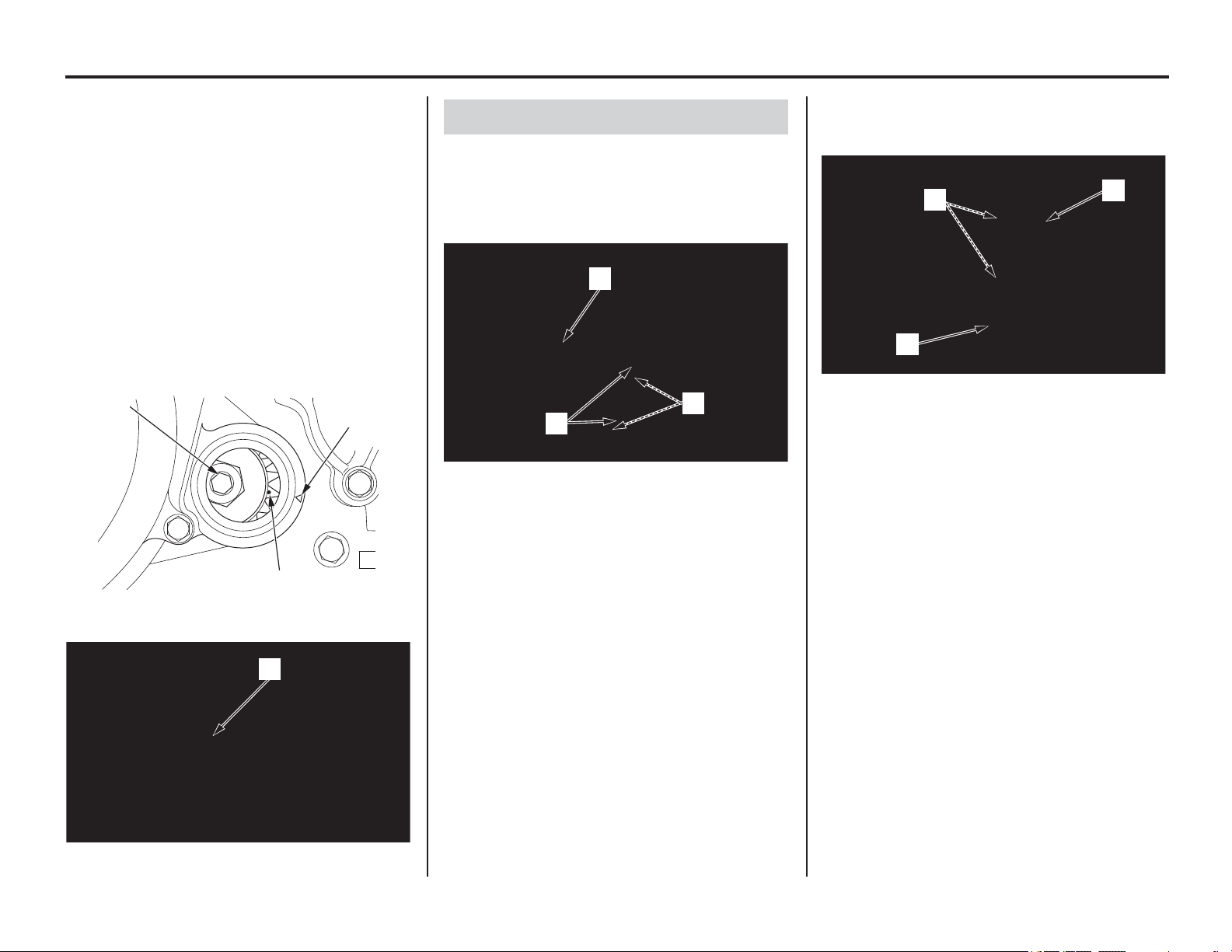
4. Rotate the crankshaft by turning the primary
drive gear bolt (2) clockwise until aligning the
punch mark (3) on the primary drive gear with
the “ǻ” mark (4) on the right crankcase cover.
In this position, the piston may either be on the
compression or exhaust stroke.
If the crankshaft passed the punch mark, rotate
the primary drive gear bolt clockwise again
and align the punch mark with the “ǻ” mark.
The inspection must be made when the piston
is at the top of the compression stroke when
both the intake and exhaust valves are closed.
This condition can be determined by moving
the exhaust rocker arm (5). If it is free, it is an
indication that the valves are closed and that
the piston is on the compression stroke. If it is
tight and the valves are open, rotate the
primary drive gear bolt 360° and realign the
punch mark to the “ǻ” mark.
1. Set the piston at TDC on the compression
stroke (page 66).
2. Measure the intake valve clearance by
inserting a feeler gauge (1) between the valve
lifters (2) and intake cam lobe (3).
3. Measure the exhaust valve clearance by
inserting a feeler gauge (1) between the
exhaust rocker arm (4) and shims (5).
Valve Clearances:
If intake valve clearance and exhaust valve
clearance need adjustment, see Camshaft Removal
(page 68) and select the correct shim for each
valve.
(2) primary drive gear bolt
(4) “
ǻ” mark
(3) punch mark
(5) exhaust rocker arm
(2)
(3)
(4)
(5)
Valve Clearance Inspection
(1) feeler gauge
(2) valve lifters
(3) intake cam lobe
(1)
(3)
(2)
(1) feeler gauge
(4) exhaust rocker arm
(5) exhaust valve shims
IN: 0.005 ± 0.001 in (0.12 ± 0.03 mm)
EX: 0.011 ± 0.001 in (0.28 ± 0.03 mm)
(5)
(1)
(4)
Loading ...
Loading ...
Loading ...