Loading ...
Loading ...
Loading ...
38
Alternate Concentric Terminal Installation: Continued
WARNING: Do not operate the water heater with the
rain cap and elbow removed or recirculation of combustion
products may occur. The vent and combustion air-inlet
systems may also take in water, causing damage to the
water heater. Failure to follow this warning could result in
damage to the unit, improper operation, personal injury, or
death.
STEP 5:
From the outside, slide the vent pipe assembly
through the combustion air-inlet pipe and
cement the rain cap to the combustion air-inlet
pipe. From the inside, cement the wye fitting to
the combustion air-inlet pipe. (See Figure 2)
STEP 6:
Complete the installation of the remainder of
the vent and combustion air-inlet systems as
required on pages 12 thru 20 of the Use and
Care manual.
SECTION 2: VERTICAL INSTALLATION
STEP 1:
Cut a 5” diameter opening in the roof and install
field-supplied weather-seal boot/flashing for a
4 1/2” PVC pipe.
STEP 2:
From inside, insert the 4 1/2” diameter
combustion air-inlet pipe up through the seal
boot, ensuring that no insulation or debris
accumulate in the pipe. Ensure termination
height is above the 12” minimum clearance
anticipated snow level.
STEP 3:
Secure the combustion air-inlet pipe using a
field supplied perforated strap or a suitable type
material. (See Figure 4)
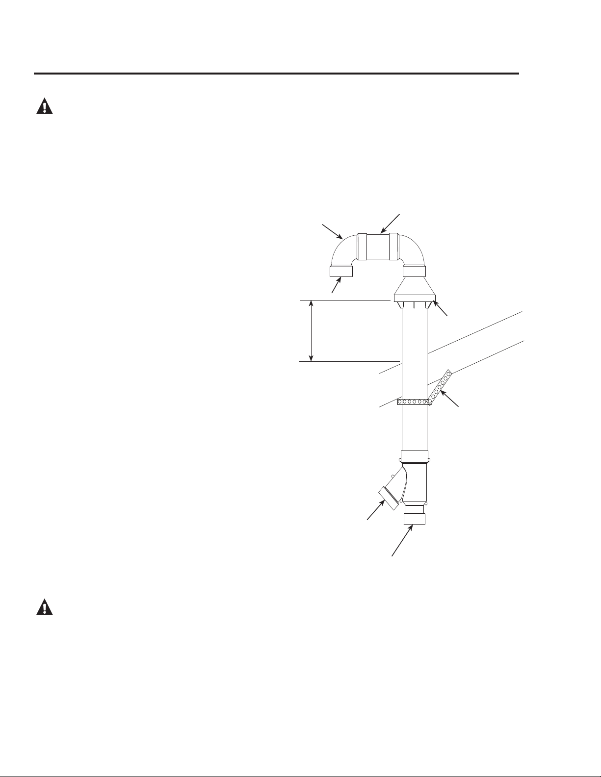
STEP 4:
Assemble the vent pipe assembly by cleaning
and cementing the rain cap to the 2 7/8”
diameter exhaust pipe. Assemble the supplied
90° elbow by cleaning and cementing to the
rain cap. Assemble the field supplied SDR 35
PVC connector and SDR 35 90° PVC elbow by
cleaning and cementing together as shown in
Figure 4.
WARNING: Do not operate the water heater with
the rain cap removed or recirculation of combustion
products may occur. The vent air pipes may also take
in water, causing damage to the water heater. Failure
to follow this warning could result in damage to the
unit, improper operation, personal injury, or death.
STEP 5:
From the roof top, slide the vent pipe assembly
down through the intake pipe and cement the
rain cap to the intake pipe. From the inside,
cement the wye fitting to the intake pipe. (See
Figure 4)
STEP 6:
Complete the installation of the remainder of
the vent and combustion air-inlet systems as
required on pages 12 thru 20 of the Use and
Care manual.
NOTICE: The concentric terminal assembly is designed
to accept 3" diameter pipe. If a 2" diameter pipe is
used a 3" to 2" reducer fitting must be installed to
the vent and combustion air inlet connections of the
concentric terminal assembly.
Alternate Vent Termination
Exhaust
Field Supplied
Strap
Combustion Air- to
Water Heater (3")
Vent From Water Heater (3")
Field Supplied
PVC Connector
Field Supplied
90° Elbow
FIGURE 4
# Min. 18 in.
Above Roof or
12" above
Anticipated Snow
Level; which-
ever is highest
and
Max. 24 in.
Above Roof
(Without
Additional
Support)
Air Intake
#
Loading ...
Loading ...