Loading ...
Loading ...
Loading ...
23
For increased energy efficiency, some
water heaters have been supplied with
factory installed 3/4” NPT heat traps in
the hot outlet line and cold water inlet
line.
These heat traps may require a minimum
of one (1) 90° 3/4” NPT elbow and may
require an additional 90° 3/4” NPT elbow
or a 3/4” coupling depending on your
installation needs. See Illustration of
nipples and heat traps on page 36.
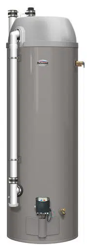
For increased energy efficiency, this water heater has been supplied with a 2 3/8”
section of T&P insulation. Install the insulation as shown below.
Temperature & Pressure (T&P) Insulation Installation
Slip the insulation cover over the T&P
Valve through the center hole and align
the hole in the side with the opening of
the T&P Valve.
Ensure the T&P Valve opening is
not obstructed by the insulation.
Typical Side Connect T & P
Arrangement.
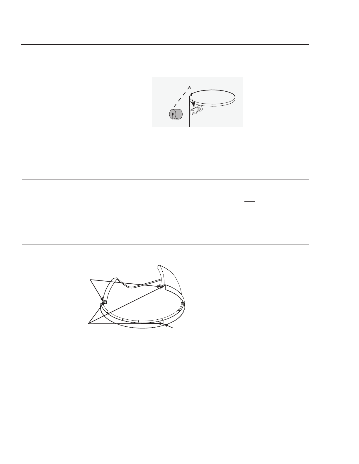
Top Cap Installation
Read these instructions thoroughly and
make sure you understand all the steps
and procedures before proceeding with the
installation.
Carefully remove the Top Cap from the wa-
ter heater carton. Install the water heater as
specied per this Use & Care Manual.
NOTICE: Also see information as detailed
in “Water Supply Connections” section.
Locate the small plastic bag containing the
three (3) Dual Lock
®
strips and two (2)
sheet metal screws to be used to attach the
Top Cap in the Use & Care Manual bag.
Peel off one side of the Dual Lock
®
strips
and rmly press near the Top Cap mount-
ing tabs and the inside center front of the
rim on the Top Cap, see gure on left.
Peel off the other side of the Dual Lock
®
strips and place the Top Cap on the top
front center of the water heater ensuring
that it is aligned correctly and properly
positioned on top of the water heater. Press
rmly to ensure proper attachment is made.
Align holes in mounting tabs on the Top
Cap with the holes in the top of the heater
then secure the Top Cap to the water heater
with the two (2) #8 sheet metal screws
(supplied).
IMPORTANT: Do not over tighten the
screws as this may damage the Top Cap.
3 Dual Lock
®
Strips
2 screws
(mounting
tabs)
Inside Center
Front
Inside
Outside
Top Cap View
Heat Trap
Loading ...
Loading ...
Loading ...