Loading ...
Loading ...
Loading ...
21
Wiring
If local codes permit, the water heater may
be connected to electric service with the
power cord provided (DO NOT use an
extension cord). A grounding receptacle is
required.
If local codes do not permit the use of
cord connections, a 120 V, 60 Hz power
supply, with suitable disconnecting means,
must be connected to the black and white
leads in the heater control enclosure.
The maximum current draw is
approximately 5.0 amps.
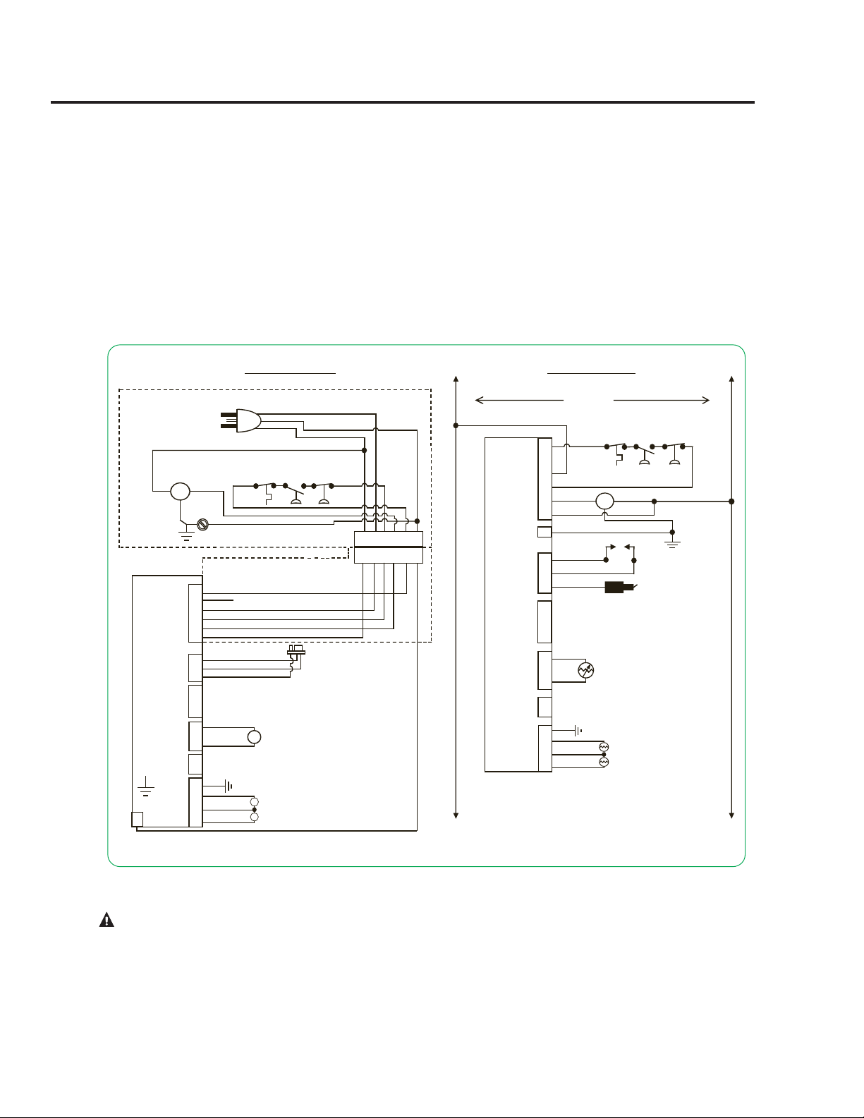
The water heater must be electrically
grounded in accordance with local
codes, or, in the absence of local codes,
in accordance with latest edition of the
National Electric Code ANSI/NFPA No.
70. Refer to the figures below for water
heater internal wiring.
CAUTION! Label all wires prior to disconnection when servicing controls. Wiring errors can cause improper and
dangerous operation. VERIFY PROPER OPERATION AFTER SERVICING!
120V / 60 Hz LESS THAN 5 AMPS
AX5168
708.633.1166
Rheem
AX5168
5.5” X 6.5”
Black
ST
4/3/12
9-1554
{ENGLISH}
GAS VALVE
INTELLI-VENT ELECTRONIC CONTROL
1 2 3 4 5 6
W BK R Y BL G
WIRE HARNESS THAT RUNS FROM BLOWER
ASSEMBLY TO GAS VALVE CONTROL
FLAMMABLE
VAPOR SENSOR
H
G
N
120 VAC PLUG FOR POWERVENT
BLOWER ASSEMBLY
POWER
VENT BLOWER
ASSEMBLY
BLOWER
6 PIN CONNECTOR
W
BK
R
Y
BL
G
CONNECTOR DIAGRAM
SCREW
GND
N
1
2
3
4
5
6
GAS VALVE
INTELLI-VENT ELECTRONIC CONTROL
GND
MOT
120 VAC
N
SCHEMATIC DIAGRAM
BL
N/C
BK
R
W
Y
MOT
BLOWER
NOTE: IF ANY OF THE ORIGINAL WIRE SUPPLIED WITH THE APPLIANCE
MUST BE REPLACED, IT MUST BE REPLACED WITH A 18 GA, 600 V,
105º C WIRE.
BK
G
W
TEMPERATURE
SWITCH NC
TEMPERATURE
SWITCH NC
1
2
3
4
5
6
N/C
BL
BK
R
Y
W
G
H
H
1
2
3
1
2
3
4
1
2
3
GND
IGNITER AND
FLAME SENSOR
W
W
W
FV
BK
BK
COMM PORT
1
2
AUX PORT
BK
BL
G
R
W
Y
=
=
=
=
=
=
BLACK
BLUE
GREEN
RED
WHITE
YELLOW
1
2
3
FLAME SENSOR
W
W
IGNITER
W
VAC
SW NO
VAC
SW NC
VAC
SW NO
VAC
SW NC
1
2
3
4
COMM PORT
BK
BK
1
2
3
4
1
2
THERMISTORS
3
4
BK
R
R
G
FLAMMABLE
VAPOR SENSOR
*
* NOT AVAILABLE ON ALL MODELS
AUX PORT
*
THERMISTORS
BK
R
R
G
TS2
TS1
1
3
2
1
2
Loading ...
Loading ...
Loading ...