Loading ...
Loading ...
Loading ...
18
Installing the Water Heater
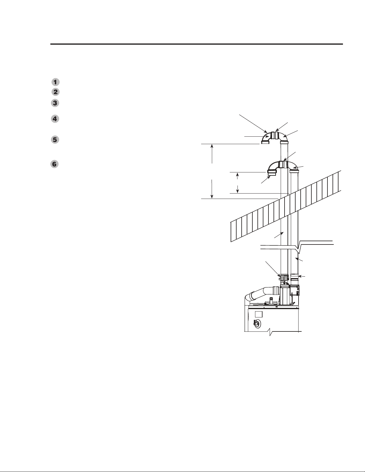
Vertical Vent and Combustion Air-Inlet Installation
The location of the vent and combustion air-inlet
terminals depends on the following minimum clearances
and considerations.
Minimum 12 in. above roof.
Minimum 12 in. above anticipated snow level.
Maximum 24 in. above roof level without additional
support for vent.
Four (4) ft. from any gable, dormer or other roof
structure with building interior access (i.e., vent,
window, etc.).
Ten (10) ft. from any forced air inlet to the building.
Any fresh or make-up air inlet such as a dryer or
furnace area is considered to be a forced air inlet.
Maintain a minimum horizontal distance of
12 in. between the vent and combustion air-inlet
terminal center lines.
Determine the locations for the vent and combustion
air-inlet terminals then make two (2) holes through the
roof and interior ceiling(s) to accommodate the vent and
combustion air-inlet pipes.
Assemble the vent pipe assembly.
Install the vent system and attach it to the vent connector
fitting on the water heater’s blower assembly.
Horizontal lengths of the vent system must slope upwards
a minimum of 1/8 in. per foot.
Install the combustion air-inlet system and attach it to the
combustion air-inlet rubber coupling on the water heater’s
combustion air-inlet tube assembly.
Support vertical and horizontal lengths of the vent and
combustion air-inlet systems as previously mentioned.
Determine the vent and combustion air-inlet terminal
heights and cut the pipe accordingly. Insert lengths of vent
and combustion air-inlet pipes through the ceiling wall as
shown.
Install adequate flashing where the vent and combustion
air-inlet pipes pass through the roof.
Connect vent elbow onto vertical pipe through roof.
Connect a short piece of pipe approximately 3 in. between
the terminals and elbows.
Exhaust Vent and Combustion Air-Inlet
Pipe Through Roof
-B-
d
.008
# Min. 12 in.
Above Roof or
above Anticipated
Snow Level;
whichever is
highest
and
Max. 24 in.
Above Roof
(Without
Additional
Support)
Terminals with 1/2 in. mesh
Protective Screens and
Termination Restrictors Inside.
Elbow
Short Piece of Pipe
Exhaust Vent
#
Combustion
Air-Inlet
#
Short Piece of Pipe
Exhaust Vent
Vent Connector
Combustion
Air-Inlet
Rubber
Coupling
Wind
Vane
Loading ...
Loading ...
Loading ...