Loading ...
Loading ...
Loading ...
10
Installing the water heater
A new combination temperature and pressure relief valve, complying with the Standard for Relief Valves
and Automatic Gas Shut-Off Devices for Hot Water Supply Systems, ANSI Z21.22, is supplied and must
remain in the opening provided and marked for the purpose on the water heater. No valve of any type should
be installed between the relief valve and the tank. Local codes shall govern the installation of relief valves.
Relief Valve
The pressure rating of the relief valve
must not exceed 150 PSI, the maximum
working pressure of the water heater as
marked on the rating plate.
The Btuh rating of the relief valve must
equal or exceed the Btuh input of the
water heater as marked on its rating plate.
Position the outlet of the relief valve
above a suitable open drain to eliminate
potential water damage. Piping used
should be of a type approved for hot water
distribution.
The discharge line must be no smaller
than the outlet of the valve and must
pitch downward from the valve to allow
complete drainage (by gravity) of the
relief valve and discharge line.
The end of the discharge line should not
be threaded or concealed and should be
protected from freezing. No valve of
any type, restriction, or reducer coupling
should be installed in the discharge line.
To Fill the Water Heater
Make certain that the drain valve is
closed, then open the shut-off valve in the
cold water supply line.
Open each hot water faucet slowly to
allow the air to vent from the water
heater and piping.
A steady flow of water from the hot water
faucet(s) indicates a full water heater.
Do not allow the flammable vapor sensor
to become submerged in water.
WARNING: The tank
must be full of water before
heater is turned on. The
water heater warranty does
not cover damage or failure
resulting from operation
with an empty or partially
empty tank.
Condensate Management
This water heater generates condensate
and requires a drain to be located in close
proximity to allow condensate to drain
safely. The drain line and fittings should
be installed per installation instructions.
Be sure the condensate runs freely to
the drain and does not accumulate in the
condensate trap or the condensate line. In
cold climates, precautions may need to be
taken to ensure that the condensate drain
lines do not freeze. A water proof heat
tape may be used to prevent freezing of
condensate lines.
It is recommended that the condensate trap
be primed by filling the trap with 1/4 cup
of tap water before connecting the drain
lines.
• Condensate is mildly acidic and should
be collected and disposed per local codes.
Certain local codes require condensate
to be neutralized before it is disposed.
Neutralizer kits are available. Contact
your installer or plumbing contractor.
• Use only PVC, CPVC pipe or
flexible tubing suitable for use with flue
condensate as drain line. If flexible tubing
is used ensure that there are no bends or
twists and has gradual slope to condensate
drain.
• The drain line (along its entire length)
must be at least the same diameter as the
drain of the condensate trap (1/2”).
• The drain line must be short as possible
and have a downward slope towards the
condensate drain. If suitable slope is not
provided, the drain line can get blocked
and will cause improper operation of the
water heater. If a downward slope cannot
be provided, a condensate pump should
be used to pump condensate to a suitable
drain.
• The end of the drain line should be open
to the atmosphere. The end should not be
under water.
• Do not connect the drain line directly to
the sewer drain.
• Do not connect the drain line with
drains from other appliances.
• Do not drain condensate into the water
heater drain pan.
• Do not drain condensate over public
way, walkway or other areas where it will
create slippery condition, which could
lead to personal injury.
NOTICE: If water
appears on the floor DO
NOT assume the tank in
leaking, check venting
and condensate line
connections.
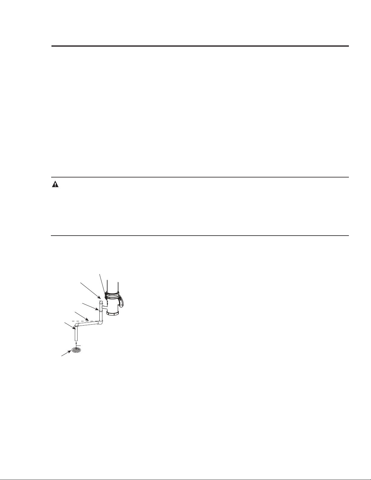
Condensate Trap
Condensate Riser
(1/2" PVC pipe
supplied)
Downward Slope
Condensate Drain
1/2" PVC tee (supplied)
6" air gap
NOTICE: Water Heater
should be leveled for
proper condensate
drainage.
Drain Line
Loading ...
Loading ...
Loading ...