Loading ...
Loading ...
Loading ...
37
Alternate Vent Termination
INSTALLATION INSTRUCTIONS
for Alternate Concentric Terminal:
Use only Rheem 3" vent kit part number SP20245.
IMPORTANT: Read these instructions thoroughly and make sure you understand all steps and proce-
dures before proceeding with the installation.
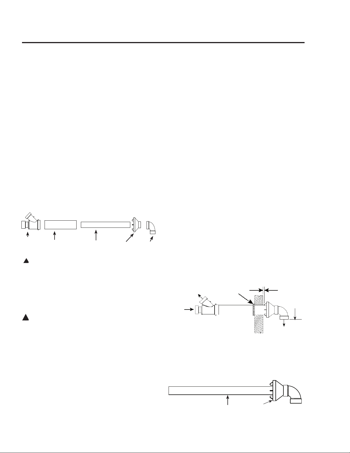
INSPECT SHIPMENT:
Inspect contents for possible missing or damaged
components. (See Figure 1) This kit includes:
Qty. 1 (one) – 3 3/16” x 7 1/2” PVC Modified
Reducer Rain Cap (part #
68-23421-03C)
Qty. 1 (one) – 2 7/8” Diameter PVC Exhaust
Pipe 37 1/8” long (part #
68-23421-03B)
Qty. 1 (one) – 4 1/2” Diameter PVC Air-
inlet Pipe – 24” long (part #
68-23421-03A)
Qty. 1 (one) – 3 1/4” x 3 3/4” x 4 7/8” PVC
Wye (part # 68-23421-03D)
Qty. 1 (one) – SDR 35 90° PVC Elbow
!
WARNING: These instructions are intended as an
aid to qualified service personnel for proper
installation, adjustment, and operation of this kit.
Read these instructions thoroughly before attempting
installation, adjustment, or operation. Failure to
follow these instructions can result in improper
installation, adjustment, service, or maintenance
possibly resulting in fire, electrical shock, property
damage, personal injury, or death.
!
WARNING: This kit is to be used only for vent &
combustion air-inlet termination for Power Direct Vent
Gas Water Heaters. Do not use this kit to terminate
any other type of appliance. Failure to follow this
warning could result in fire, personal injury, or death.
LOCATION: The Concentric Vent & Combustion Air-
Inlet Termination Kit can be installed in a horizontal or
vertical (roof) orientation. Before installation procedures
begin, determine the best location for the termination kit.
IMPORTANT: When installing the kit, consider
the following when choosing a location:
• Kit is positioned where vent gases will not
damage nearby structure.
• Kit is positioned so that wind will not cause
combustion products, leaves, snow, or other
debris from entering the combustion air-
inlet.
• Kit is positioned where it will not get
damaged by foreign objects (i.e.: balls,
stones, etc.).
• Kit is positioned where vent gases will not
be inhaled or cause a nuisance.
NOTE: Ensure that the heights of the vent and/
or combustion air-inlet openings are above the
anticipated snow level by a minimum of 1 ft.
SECTION 1: HORIZONTAL INSTALLATION
STEP 1:
Cut a 5” diameter opening in the sidewall and install field
supplied weather-seal boot/flashing for a 4 1/2” PVC pipe.
STEP 2:
From inside, insert the 4 1/2” diameter combustion air-
inlet pipe through the seal boot so that a maximum of 1”
clearance occurs between the outside wall and rain cap
fins (See Figure 2). Ensure that no insulation or debris is
accumulated in the pipe.
STEP 3:
Secure the combustion air-inlet pipe using a field supplied
perforated strap or a suitable type material. (See Figure 2)
STEP 4:
Assemble the vent pipe assembly by cleaning and
cementing the rain cap to the 2 7/8” diameter vent pipe.
Assemble the supplied SDR 35 90° PVC elbow by
cleaning and cementing to the rain cap. (See Figure 3)
Vent Pipe Assembly
Wye
4 1/2 " Dia Pipe
2 7/8" Dia Pipe
Rain Cap
Elbow
FIGURE 1
FIGURE 3
1" Max
Combustion Air-Inlet
to Water Heater (3")
Field Supplied
Strap
Vent from Water
Heater (3")
Exhaust
FIGURE 2
Termination
Openings
12 in. min.
above grade
or above
anticipated
snow level
Air Intake
Loading ...
Loading ...
Loading ...