Loading ...
Loading ...
Loading ...
Water Maze Compact CoAg • 9.801-506.0-D
11
WATER TREATMENT SYSTEM
DEALER MANUAL
INSTALLATION & STARTUP INSTRUCTIONS
98015060-12
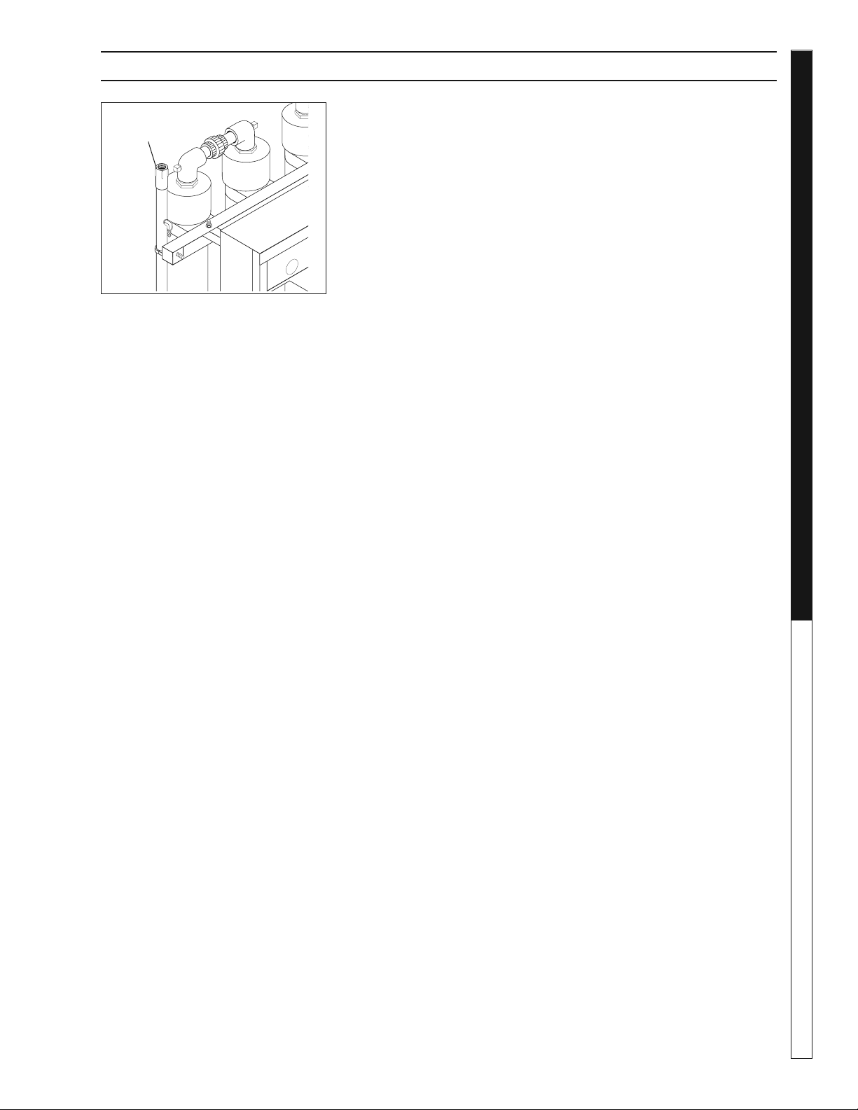
STEP 11: Assemble a fl ex hose with cam-lock fi ttings
and install from the treated water outlet connection
to the inlet connection on the indexing polishing fi lter
(IPF) (optional). We recommend you install a 1.5 inch
ball valve inline with this connection to regulate the
fl ow into the IPF.
If you are not using an IPF, this hose would connect to
a treated water holding tank or go to discharge.
STEP 12: Adjust the fl ow rates of the in-feed water and
the chemical injection pumps based on the following
Process Objectives:
1. As the infl uent water enters into the in-feed tank,
the in-feed pump control fl oat will rise and signal
the in-feed pump to turn on and begin to pump
water into the Compact CoAg unit.
2. Initial settings:
a. Set the fl ow control as noted in Step #7.
b. Set each peristaltic pumps (coagulant and
fl occulant) based on the designated settings
for this application. Refer to the bench scale
testing procedures conducted on a new water
sample for this application (as noted on page
#17 of this manual).
c. Turn the CoAg+ (coagulant) pump on.
d. Turn the EC+ (fl occulant) pump off (until step
4 below is completed).
3 Locate the water sampling tap located between the
upper portion of the mixing tubes (between the 2nd
and 3rd tubes. Refer to component identifi cation
page). As water is fl owing, drain water sample(s)
into clear sided container to confi rm if coagulation
is taking effect.
a. Compare the sample to an untreated water
sample. You are looking for small formations of
"pin-fl occ"or globlets of matter forming within
the body of water.
b. Normally, it is easier to see the pin-fl occ forming
near the top portion of the cup.
Treated Outlet
Connection
4. Adjust the infl uent fl ow control valve up or down
and/or the feed speed of the coagulant pump
up or down until the "pin-fl occ" is acheived.
NOTE - the objectives are to:
i. Maximize the infl uent water fl ow rate.
ii. Minimize the speed (eg., consumption)
of chemical injection.
5. Turn on the EC+ chemical fl occulant pump. Take
samples of water (as noted in #4 above). Adjust
the EC+ pump speed until you see large gather-
ing of matter forming within the body of water.
As noted above, the objective is to minimize the
consumption of chemical fl occulant, and create
a tight gathering of "pin-fl occ".
STEP 13 : The pH controller must be programmed
before start up. Press the up and down arrows at
the same time, then let go to enter programming.
"AC" stands for acid injection and "bA" stands for
caustic injection. To toggle between the two, just
press the up or down arrow one time. The control-
ler will now show the fl ow switch setting (FLO).
"FO" stands for fl ow switch OFF and F1 stands
for fl ow switch ON. Set to F1. To toggle between
the two, press the up or down arrow one time.
Leave controller alone till the pH is showing on
LED screen.
STEP 14 : To calibrate pH:
- Press (CALIBRATION) button
- Press (pH) button: display fl ashes
- Use the (UP) or (DOWN) arrows to adjust
the value
- Press (CALIBRATION) button to again
save value
STEP 15 : To change the setpoint:
- Press (SETPOINT)
- Press (pH) button: display fl ashes
- Press (UP) or (DOWN) arrows to adjust
the setpoint
- Press (SETPOINT) button to again
save value
Loading ...
Loading ...
Loading ...