Loading ...
Loading ...
Loading ...

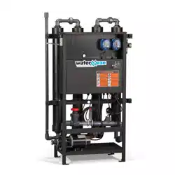
Water Maze Compact CoAg • 9.801-506.0-D
DEALER MANUAL WATER TREATMENT SYSTEM
10
LOW
LIQUID
PUMP
ON
98015060-10
INSTALLATION & START-UP INSTRUCTIONS
STEP 8: Unplug the float level
switch connector. Add the 5 gal-
lon container with EC+ Floccu-
lent. Install EC+ pump tubing into
the 5 gallon container. Recon-
nect the level switch connection.
NOTE: Dial may be readjusted to
produce the desired fl occulent.
STEP 9: Add the 5 gallon con-
tainer with CoAg+ solution to its
location under the CoAg+ metering
pump. Install the conductivity pump
tubing into the 5 gallon container.
NOTE: Dial may be readjusted to
produce the desired conductivity
and fl occulant.
Infeed
Pump
98015060-11
98015060-15
STEP 10: Turn "On" both metering
pumps. The switches are located
on the side of each pump. You will
need to "prime" each line (with
CoAG+ or EC+ chemicals) by hold-
ing each metering pump switch in
it "prime postion". Release the
switch to its normal "run" position.
STEP 6: Press and hold power
switch in ON position for 3 sec-
onds then release.
LOW
LIQUID
PUMP
ON
STOP
RUN
9.
8
07-59
7.
0
98015060-14
ON
OFF
Power
Switch
CoAg+
EC
+
EC
+
Float Level
Switch
Float Level
Switch
98015060-17
STEP 5: Fill the sump pit with (waste
water source) water.
STEP 7: With the (optional) infeed
pump/sump pump running, adjust
the incoming fl ow rate with the
flow control valve supplied as
part of the inlet manifold on the
Compact CoAg unit.
• For applications with the IPF unit
immediately downstream, the
maximum flow rate will likely be
less than 5 or 6 GPM
• For applications with a cone-
bottom receiver tank immediatley
after the Compact CoAg unit, the
flow rates may be up to 20 GPM.
NOTE: Until you are actually treat-
ing water (with chemical pumps
turned on), the pumped water
should be directed back to the
sump pit.
NOTE: Refer to Process
Objectives on next page.
EC
+
pH
CoAg+
"Prime/Run/Off"
Rocker Switch
Sump
Pit
Run Switch
Loading ...
Loading ...
Loading ...