DEALER MANUAL
For the dealer nearest you, consult our web page at www.wmaze.com
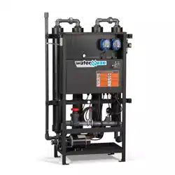
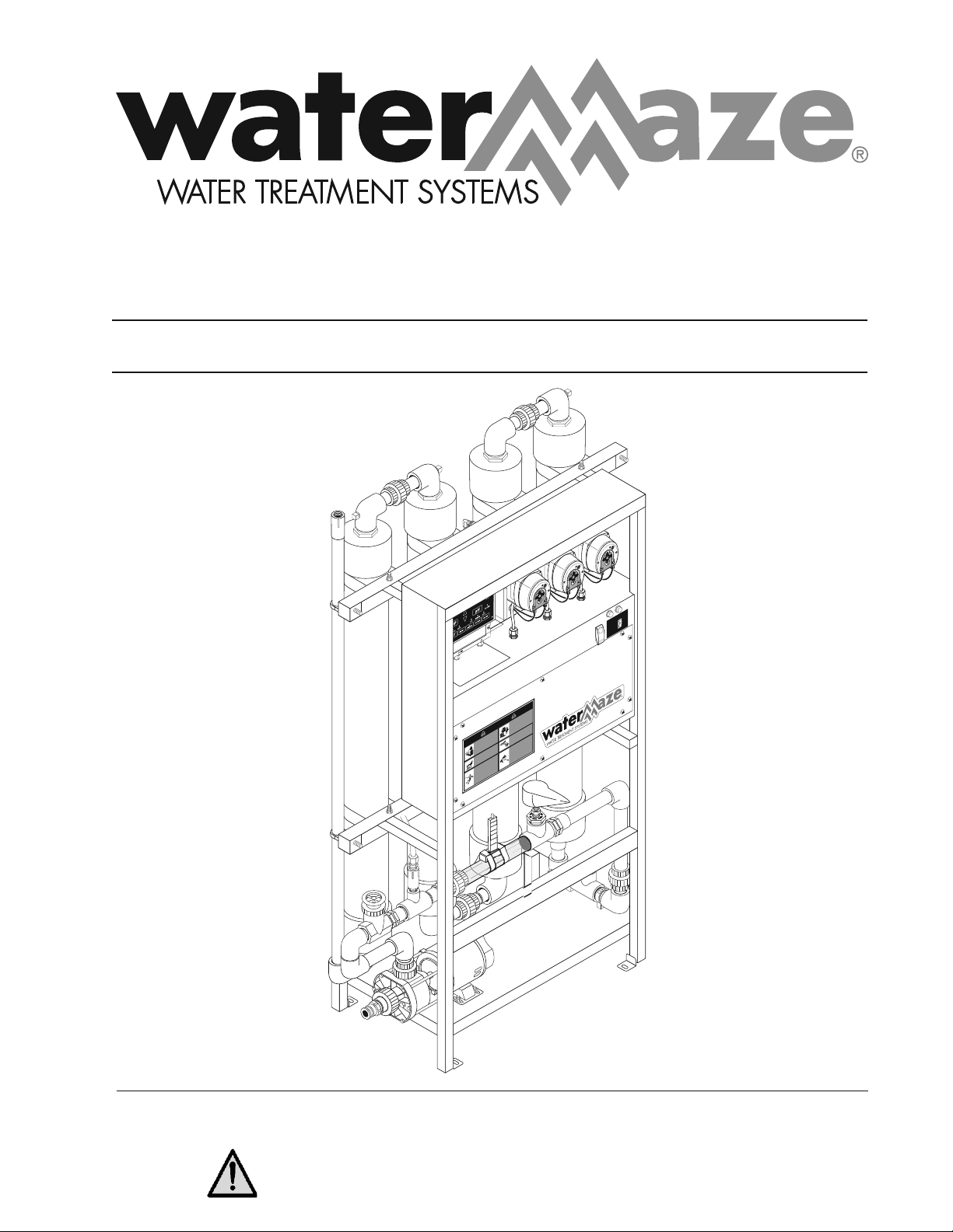
■ Compact CoAg Water Treatment System
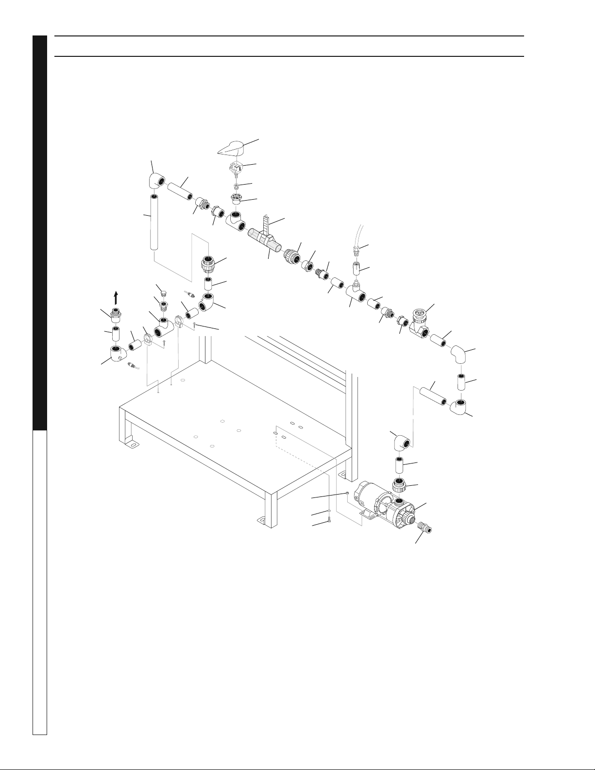
98015060-1
ORP SENSOR
Ph SENSOR
RISK OF INJURY—
P
R
O
TECTIVE
EYEWEAR AND
CL
O
THING MUST
BE
WORN
.
when
oper
ating this ma
-
chin
e
.
P
R
O
TEJ
ASE LOS OJOS CU
-
AND
O
se opere este equip
o
.
DES LUNETTES DE SECURITE
DOIVENT ETRE PO
R
TEES
lorsque
v
ous operez cet appareil.
WARNI
N
G
PREC
AUCION /
A
VE
RTISSEMENT
T
O REDUCE
THE
RISK OF INJU
R
Y
READ OPER
A
T
OR’S
MAN
U
AL
CAREFUL
LY
BEFORE USING.
THIS MACHIN
E
T
O
BE USED ON
LY BY
Q
U
ALIFIED
OPER
AT
ORS.
LEA EL MAN
UAL OPERA
CION AN
-
TES DE USARSE
. ESTE E
Q
UIPO
DEB
E SER USADO SOLAMENTE
POR OP
ERADORES CALIFICA
-
DOS.
LIRE LE MANUEL DE
L
’OPER
A
TEUR
AVANT UTILISA-
TION
.
CET APPAREIL DOIT ETRE
UT
I
LISE PAR DES
OPERA
T
EUR
S
Q
UA
L
IF
IES
.
RIESGO DE ELEC
TR
OC
U
CIÓN
— Conecte el enchu
f
e en un con
-
tacto a
decuad
o
.
Mantenga todas
las connecciones secas y ar
r
iba del
suel
o
.
No rocie componentes eléct
r
i
-
co
s
.
Desconecte la corriente eléct
r
ica
antes de dar se
rvici
o
.
RISQ
UE D’ELECT
R
OCUTION
— Relier à des p
r
ises
a
v
ec mise à la
terre seulement
.
T
ous les fils doi
v
ent
être mainte
n
us secs et étre suspen
-
du
s
.
No jam
ais projeter de l’eau sur
les composantes et fils élect
r
ique
s
.
Couper l’alimentatation élect
r
ique
a
v
ant de f
aire une répa
r
ation.
RISK OF
ELECTR
OCUTION
.
Connect only to
prope
r
ly grounded
outlet
.
K
eep all con
-
nections d
ry and off
the
ground.
K
eep
spr
a
y
a
w
a
y from
electr
ical wi
r
ing
and components
.
Disconnect from
electr
ical supply
before se
r
vicing.
RISK OF
INJECTION OR
SEVERE INJU
R
Y
T
O PERSONS.
K
eep clear of
nozzl
e
.
H
O
T DISCHARGE
FLUID
.
Do not touch or
direct discharge
stream at person
s
.
RIESGO DE PENETR
A
CIÓN O
LESIONES SEVERAS A PERSO
-
NAS.
Manténgase fue
r
a del alcance
de boquilla
.
DESCARGA DE
AG
U
A CALIENTE
A A
LT
A PRESION
—
No toque ni
di
r
ija el flujo del agua a
ot
r
a
s perso
-
na
s
.
RIS
Q
UE DE BLESSURES.
Se tenir
loin des
b
uses
.
E
AU CH
A
UDE SOUS PRESSION A
LA SOR
TIE
— Ne pas di
r
iger le jet
d’eau
v
ers des personne
s
.
SPR
A
Y GUN
KICKS B
A
CK
.
Hold with both
hand
s
.
LA PIS
T
OLA SE MUEVE CON LA
PRESIÓN
— Sostenga con las dos
mano
s
.
LA POIGNEE PIS
TOLET RE
-
POUSSE
—
Tenir à deux main
s
.
RISK OF INJU
R
Y—
HO
T SUR
F
ACES
CAN CA
USE
B
URNS
.
Use only designed
g
r
ipping areas of
spr
a
y gun and
w
and.
SUPERFICIES CALIENTES
— Use solamente las áreas
aisladas del gatillo y la lanza.
SUR
F
A
CES CHA
UDES
—
T
oucher seulement les par
ties
isolées des poignée pistolets et
lance
s
.
8
.940-047.0
L
O
W
LI
Q
U
ID
PU
M
P
ON
S
T
O
P
R
U
N
9.
8
07-597
.
0
ON
O
FF
9.801-506.0-D
WARNING:
This product and accessories may contain a chemical known to the State of
California to cause cancer and birth defects or other reproductive harm.
For more information about this regulation: www.P65Warnings.ca.gov
Patent Pending


3
CONTENTS
Part Number ______________________________
Serial Number ______________________________
Date of Purchase ___________________________
The part and serial numbers will be found on a decal attached to
the machine. You should record both serial number and date of
purchase and keep in a safe place for future reference.
Water Maze Compact CoAg • 9.801-506.0-D
Introduction and Important Safety Issues ............................................4-5
Application and Intended Use ..............................................................6-7
Flow Diagrams ........................................................................................8
Installation & Operating Instructions .......................................................9
Installation & Start-Up Instructions...................................................10-11
Maintenance Instructions ......................................................................12
Compact CoAg Component Identifi cation ............................................. 13
Compact CoAg+ System & Control Panel View ....................................14
Metering Pump & Maintenance ........................................................15-16
Metering Pump Head Exploded View & Parts List ................................ 16
Operation & Maintenance .....................................................................17
Confi guring & Tuning Peristaltic Pumps ...........................................18-19
Troubleshooting Guides ...................................................................20-23
Pump & Plumbing Exploded View & Parts List ................................24-25
Electrical Box Exploded View and Parts List .........................................26
Control Panel Exploded View & Parts List.............................................27
Mixing Tube Assembly Exploded View & Parts List ..........................28-29
Assembly Exploded View & Parts List ..............................................30-31
Infeed Pump Exploded View and Parts Lists ........................................32
Warranty

Water Maze Compact CoAg • 9.801-506.0-D
DEALER MANUAL WATER TREATMENT SYSTEM
4
Your owner’s manual has been prepared to provide
you with a simple and understandable guide, for equip-
ment operation and maintenance, based on the latest
product information available at the time of printing. To
keep your machine in top running condition follow the
specifi c maintenance and troubleshooting procedures
given in this manual. When ordering parts please
specify model and serial number.
NOTE: Water Maze reserves the right to make chang-
es at anytime without incurring any obligations.
Owner/User Responsibility:
The owner and/or user must have an understanding
of the manufacturer’s operating instructions and warn-
ings before using this equipment. Warning information
should be emphasized and understood. If the operator
is not fl uent in English, the manufacturer’s instruc-
tions and warnings shall be read to and discussed
with the operator in the operator’s native language by
the purchaser/owner, making sure that the operator
comprehends its contents.
Owner and/or user must study and maintain for future
reference the manufacturers’ instructions.
SAVE THESE INSTRUCTIONS
This manual should be considered a permanent
part of the machine and should remain with it if
machine is resold.
When ordering parts, please specify model and
serial number. Use only identical replacement
parts.
This machine is to be used only by trained opera-
tors.
GENERAL SAFETY
INFORMATION
WARNING: When using this ma-
chine basic precautions should
always be followed, including
the following:
1. Read all the instructions be-
fore using the product.
2. To reduce the risk of injury,
close supervision is neces-
sary when a product is used
near children.
3. Know how to stop the product and bleed pressures
quickly. Be thoroughly familiar with the controls.
4. Stay alert – watch what you are doing.
5. Do not operate the product when fatigued or under
the infl uence of alcohol or drugs.
6. Keep operating area clear of all persons.
7. Do not overreach or stand on unstable support.
Keep good footing and balance at all times.
8. Follow the maintenance instructions specifi ed in
the manual.
WARNING
KEEP WATER SPRAY
AWAY FROM
ELECTRICAL WIRING.
WARNING: Wire the system for
correct voltage. Refer to the
information located on the se-
rial plate.
WARNING: All wiring must be
performed by a qualifi ed elec-
trician.
WARNING: Risk of Electric Shock
DANGER – Improper connection of the equipment-
grounding conductor can result in a risk of electro-
cution. Check with a qualifi ed electrician or service
personnel if you are in doubt as to whether the
machine is properly grounded. Have proper power
connections installed by a qualifi ed electrician.
Do not use any type of adaptor with this product.
GROUNDING INSTRUCTIONS
This product must be connected to a grounded, metal,
permanent wiring system; or an equipment-grounding
conductor must be run with the circuit conductors
and connected to the equipment-grounding terminal
located on the product.
GROUND FAULT CIRCUIT
INTERRUPTER PROTECTION
To comply with the National Electrical Code (NFPA
70) and to provide additional protection from the risk
of electric shock, this machine should only be con-
nected to a circuit protected by a ground fault circuit
interrupter (GFCI).
9. Know the system application, limitations, and
potential hazards.
WARNING: Do not use near
concentrations of flammable
or explosive fluids such as
gasoline, fuel oil, kerosene,
solvents, etc. Do not use in ex-
plosive atmospheres. Liquids
compatible with component
materials should only be used.
Failure to follow this warning
can result in personal injury
and/or property damage.
10. The main power must be brought from the circuit
breaker and wired into the electrical box on the
Compact CoAg. This power supply must be run
through conduit in compliance with local and na-
tional electrical codes. A power disconnect should
WARNING
READ OPERATOR’S
MANUAL THOROUGHLY
PRIOR TO USE.
INTRODUCTION & IMPORTANT SAFETY INSTRUCTIONS
WARNING
RISK OF
EXPLOSION: DO NOT
SPRAY FLAMMABLE
LIQUIDS.
Water Maze Compact CoAg • 9.801-506.0-D
5
WATER TREATMENT SYSTEM
DEALER MANUAL
be located near the machine for maintenance and
emergency purposes.
11. Protect all electrical cords from sharp objects,
hot surfaces, oil, sunlight, and chemicals. Avoid
kinking the cords.
WARNING: If any cords or electrical wires appear to
be frayed, damaged, or in poor condition, proceed
with caution and immediately take steps to have
the cords repaired or replaced.
12. Never make adjustments on the machine while it
is in operation, except for those prescribed in this
manual.
13. Follow the maintenance instructions specifi ed in
this manual.
14. Before servicing the machine, refer to all the MS-
DS’s on the material identifi ed in the waste stream.
You must comply with all warnings and wear all
protective clothing as stated on the MSDS’s.
15. Inlet water temperature must not exceed 85°F.
16. The best insurance against an accident is precau-
tion and knowledge of the equipment.
17. Water Maze is not liable for modifi cations or use
of components not purchased from Water Maze.
18. Personal Safety:
a. Wear safety glasses and
other applicable protective
clothing at all times when
working on this machine.
Refer to item #14 under Impor-
tant Safety Information.
b. Keep your work area clean,
uncluttered and properly
lighted
c. Replace all unused tools and equipment.
d. Keep visitors at a safe distance from work area.
19. Running the system without water will damage the
pumps and will void the warranty.
20. Release all pressure within the system before
servicing any component.
IMPORTANT SAFETY INSTRUCTIONS
WARNING
PROTECTIVE
EYE WEAR AND
CLOTHING MUST
BE WORN.
21. Drain all liquids from the component before
servicing.
22. Check hoses for weak or worn conditions before
each use, making certain that all connections are
secure.
23. Periodically inspect pump and system compo-
nents. Perform routine maintenance as required.
24. Do not touch an operating motor. Modern motors
are designed to operate at high temperatures.
25. Do not touch any electrical component with wet
hands, when standing on a wet or damp surface,
or in water.
26. The pump motors are equipped with a thermal
protector. Tripping is an indication of motor over-
loading as a result of operating at excessively high
or low voltage, inadequate wiring, incorrect motor
connections, or a defective motor or pump.
27. Keep machine from freezing.
28. Do not spray water directly at machine.
WARNING: This system contains moving parts in
the control center and in the pumps. Follow safe
practices when performing maintenance and when
troubleshooting. Disconnect the power before
servicing this machine. If the power disconnect
is out of sight, lock it in the open position and
tag it to prevent unexpected application of power.
WARNING: Make sure to take precautions when
performing maintenance on the pump in the catch
basin. Turn off the power to the pump and make
sure electrical cords are well maintained.
Water Maze Compact CoAg • 9.801-506.0-D
DEALER MANUAL WATER TREATMENT SYSTEM
6
Compact CoAg Water Treatment Unit:
The Compact CoAg water treatment unit can be
installed as a recycle or a treat & discharge water
system. The Compact CoAg may also be installed as
a component of a system that incorporates multiple
water treatment technologies. In certain applications
the constituents in the water may require additional
pre-treatment or post treatment of the fl uid stream.
To assure the best processed water quality, pretreat-
ment of the waste water should be applied to address
the following waste water characteristics:
• Heavy solids: Excessive amounts of heavy sol-
ids (especially solids that quickly fall out) should
be removed prior to entering the Compact CoAg
system.
• Free-oils (oils that are fl oating on the surface of
the water): Although the Compact CoAg will typi-
cally address both free-oils and emulsifi ed oils,
excessive amounts of free-oils should be removed
prior to entering the system.
• pH of the water: Typically, the Compact CoAg
system performs best when the pH of the infl uent
waste water is between 7 and 8. If the pH is out-
side these limits, pH adjustment will be necessary.
Consult Water Maze for recommendation.
• Post-treatment: Subject to the application re-
quirements, additional water treatment may be
required.
Consult a Water Maze representative prior to com-
bining the Compact CoAg with other pre-treating
and post treating equipment.
TCLP Testing:
TCLP is one of the Federal EPA test methods that
are used to characterize waste as either hazardous
or non-hazardous for the purpose of disposal. TCLP
is an acronym for Toxicity Characteristic Leaching
Procedure. A TCLP test may be required prior to
disposal of your solid waste. Consult a Water Maze
representative for details.
Site Preparation:
The installation site surface should be of compacted
materials, such as concrete, asphalt or pavement and
capable of supporting the Compact CoAg treatment
system.
APPLICATION AND INTENDED USE
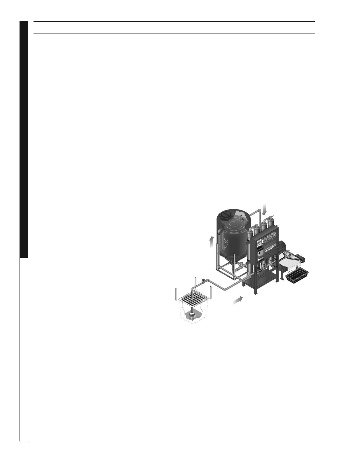
Typical Applications
This section outlines some of the common confi gura-
tions for the Compact CoAg module.
As a treatment & discharge system:
1. Compact CoAg unit receives pretreated water and
applies pH control (if required); applies chemical
coagulant and chemical fl occulent.
2. A small cone-bottom reactor tank is positioned
immediately after the Compact CoAg unit, which
allows for mixing of the chemical fl occulent and
provides additional processing dwell time.
a. This is the most (highly) recommended confi gu-
ration. (See special note* below).
b. Maximum estimated fl ow rate = up to 20 gpm
3. An IPF2-20D Indexing Polishing Filter (standard
unit, or High-boy unit), along with a lower water
retention container is positioned after the above
reactor tank. The IPF2-20D unit provides for sepa-
ration and dewatering of the gathered (fl occulated)
matter.
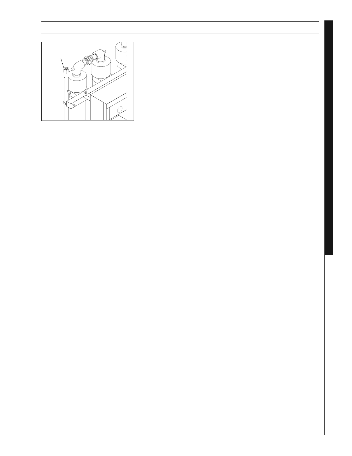
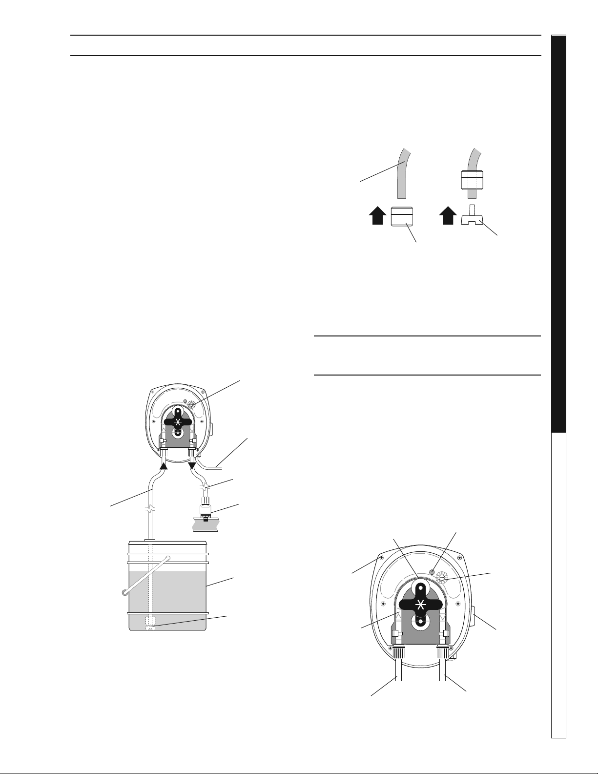
SPECIAL NOTE* – Confi guring the 150-gallon tank (as
shown), or another size of cone-bottom tank.
This tank receives the CoAg+ coagulated water (CoAg+
chemical injected in the 1st mixing tube) immediately
after the EC+ fl occulent is injected in the 4th mixing
tube. Please take note of the pipe on the inside of the
tank. It must be positioned near where the sloped-
bottom begins and it should have an elbow (45 or 90
degree) at the bottom that releases the water on an
oblique angle, which effectively allows the water to swirl
and to complete the mixing of the EC+ coagulant. Also
note the vertically oriented PVC Tee on the opposite
W
ARNING
P
R
E
C
A
U
T
I
O
N
/
ATTE
N
T
IO
N
.
.
.
.
.
.
.
.
.
.
.
.
.
.
.
.
WARNING
PRECAUTION/ATTENTION
WASTE WATER
INLET
SUMP PUMP / PIT
TO IPF
UNIT
COMPACT
CoAg UNIT
IPF UNIT
FROM
CoAg UNIT
98015060-19
The above shows a typical (most common) confi guration for
treatment & discharge (to sewer) applications.
Water Maze Compact CoAg • 9.801-506.0-D
7
WATER TREATMENT SYSTEM
DEALER MANUAL
side of the tank. Its orientation limits the release of
fl oating matter. As the fl ocked matter settles to the
bottom of the tank, the AMC-1000D auto-purge valve
will occasionally purge the matter to the IPF2-20A
Indexing Polishing Filter.
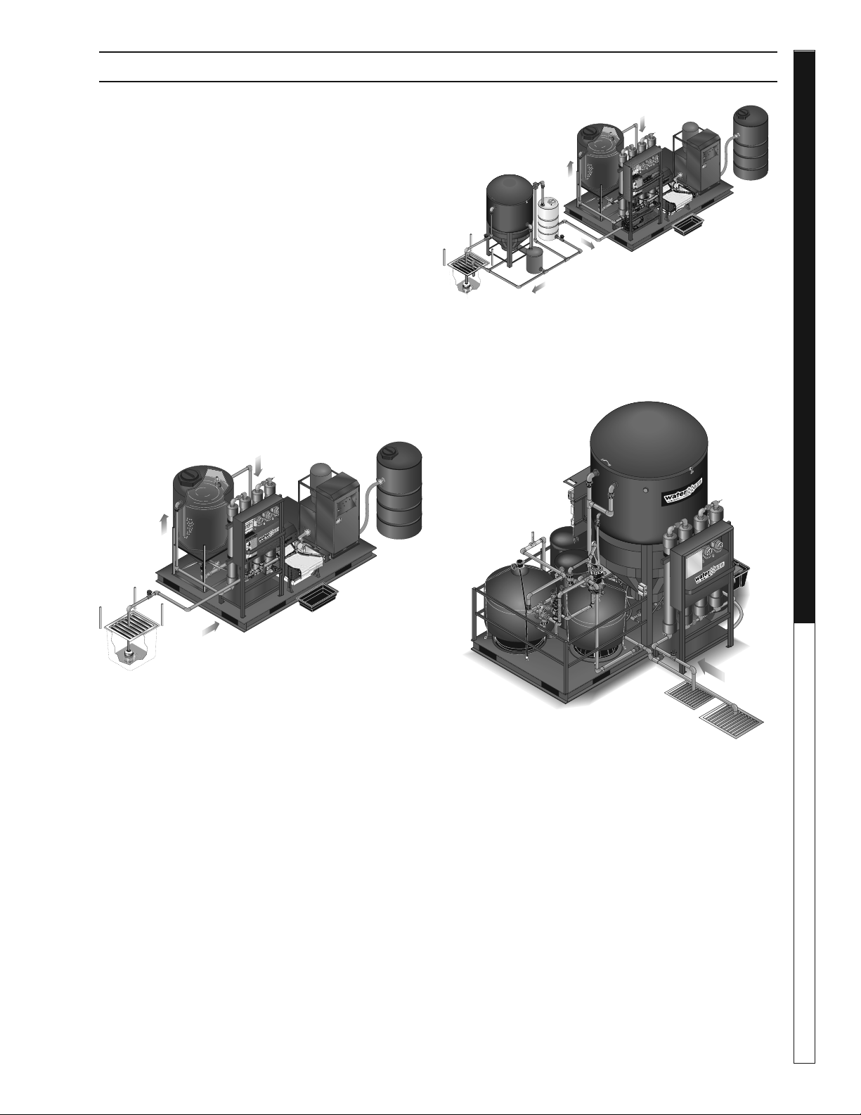
As a treatment and recycle system:
4. Typically, above items (1, 2, and 3) will be incor-
porated as pretreatment to the following compo-
nents.
5. A REC2-20A recycle control center module
draws water from the water retention container
and pumps it into a clean water storage tank
where ozone or bioremediation can be applied.
Please refer to the Water Maze product catalog
for additional information.
6. A clean water storage tank (size to be deter-
mined) will be required.
As pretreatment to, or as a supplement to an
existing water treatment system:
7. As a pretreatment (in line) module to an existing
water treatment system that is struggling with
emulsifi ed oils and / or suspended solids.
8. Confi gured as a “side-car” (e.g., pulls a partial
slip stream) from the main process water where
the existing water treatment system is struggling
with emulsifi ed oils and / or suspended solids.
APPLICATION AND INTENDED USE
Se
n
DEC
T
AC
H
/H
O
U
R
1
/
1
0
W
A
R
NI
N
G
P
R
E
CA
UTION
/
A
TT
E
N
T
I
O
N
.
.
.
.
.
.
.
.
.
.
WARNING
PR
E
CAUTION/A
TTENTION
WASTE WATER
INLET
SUMP PUMP / PIT
TO IPF
UNIT
COMPACT
CoAg UNIT
IPF UNIT
REC UNIT
FROM
CoAg UNIT
98015060-20
The above shows a typical (most common) confi guration for
treatment & recycle applications.
S
e
n
D
E
C
TA
C
H
/
H
O
U
R
1
/
1
0
W
AR
N
I
N
G
P
R
E
C
AU
T
IO
N
/A
TTE
N
T
I
ON
SUMP PUMP / PIT
WASTE WATER
INLET
RECIRCULATION LINE
OWS
CL 30
(SPECIAL)
300 GAL TANK
TO IPF
UNIT
COMPACT
CoAg UNIT
IPF UNIT
REC UNIT
FROM
CoAg UNIT
ELECTRIC AUTO
CIRCULATION
VALV E
OIL
RETENTION
BUCKET
98015060-21
The above shows a typical (most common) confi guration for
treatment & recycle with clarifi er applied for pretreatment to
remove excessive amounts of free-fl oating oils and settleable
solids.
WASTE WATER
INLET
98015060-22
The above shows how a Compact CoAg can be installed in
conjuction with another treatment system.
Available Options
• AMC-1000D Auto-Purge system—factory in-
stalled control cabinet. Includes control center
with timer control, air solenoid and 1.5 inch air
actuated/spring shut purge valve (to be installed
on a cone-bottom reactor tank positioned imme-
diately after the Compact CoAg unit).
• pH (only) controller with chemical injector pump.
Water Maze Compact CoAg • 9.801-506.0-D
DEALER MANUAL WATER TREATMENT SYSTEM
8
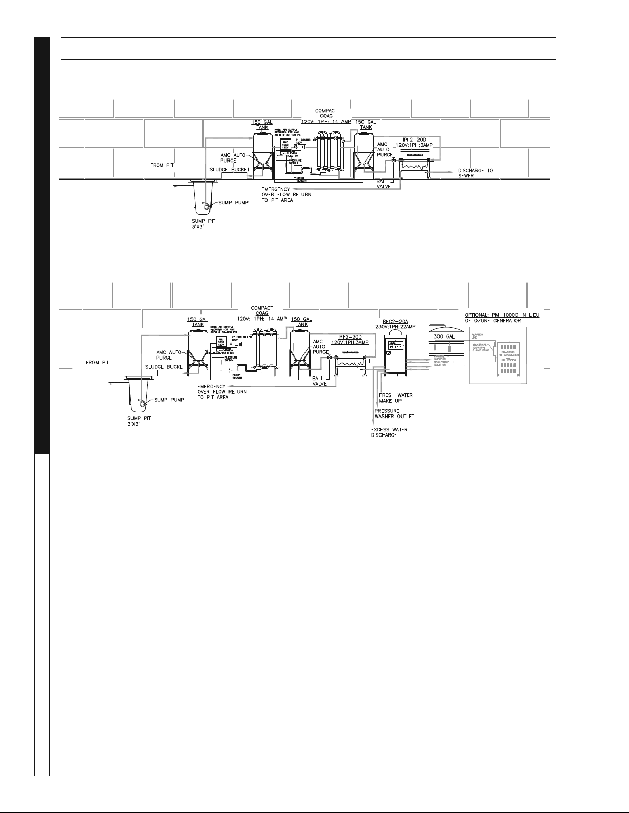
FLOW DIAGRAM
Typical Flow Diagram (Treatment And Discharge) With Pretreatment Tank
Typical Recycle Components With Optional PM-1000D Biosystem
Water Maze Compact CoAg • 9.801-506.0-D
9
WATER TREATMENT SYSTEM
DEALER MANUAL
The following instructions will provide adequate infor-
mation to fully install your Water Maze Treatment and
Recycling System. Please follow these instructions
step by step to ensure proper installation.
Equipment and Supplies
Needed for Installation
Aside from having a general assembly of tools on
hand, you will need to supply a few additional items
to complete the installation of your system.
• Forklift • Tape Measure
• Level • Hose Clamps
• Grey Flex Hose Pipe
#8.711-813.0 Sold by Ft.
INSTALLATION & OPERATING INSTRUCTIONS
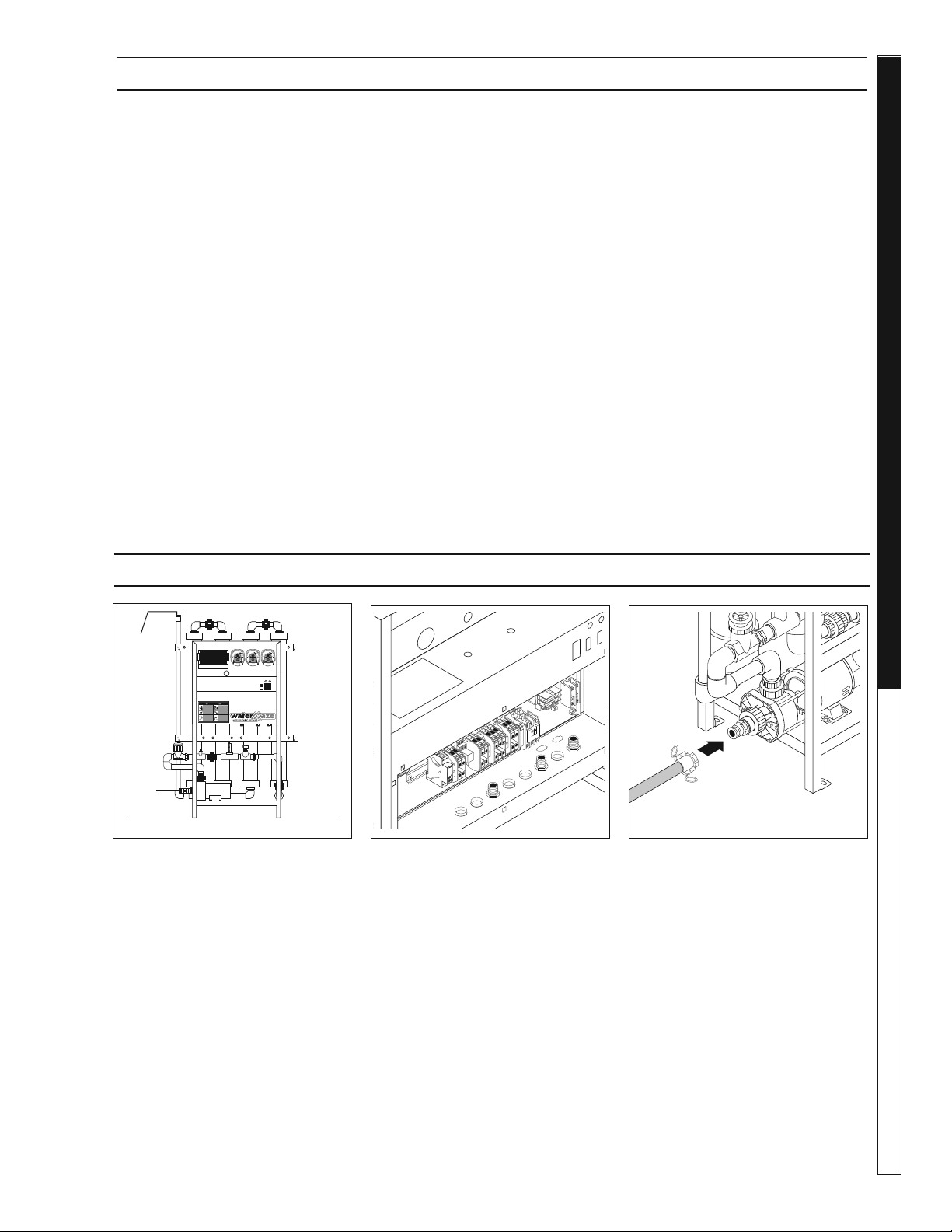
INSTALLATION & START-UP INSTRUCTIONS
STEP 1: The Compact CoAg water
treatment system must be installed
on a level surface. If surface is not
level, shimming is required.
STEP 2: Connect the inlet piping
from either the above ground feed
tank to the optional infeed pump
installed on the chassis of the
Compact CoAg. Or, connect the
inlet piping from a sump pump to
the inlet manifold on the Compact
CoAg unit.
STEP 3: An electrician will con-
nect incoming electrical power
to the power block in the electri-
cal box. When connecting to the
power supply, follow all electrical
and safety codes as well as the
most recent National Electric Code
(NEC) and Occupational Safety
and Health Act (OSHA). Ground
system before connecting power
supply.
UTILITY USAGE
Water: 30-90 PSI
Electrical: 120 Volts, 1 PH, 20 Amps
98015060-8
RISK OF INJURY—
PROTECTIVE
EYEWEAR AND
CLOTHING MUST
BE WORN. when
operating this ma-
chine.
PROTEJASE LOS OJOS CU-
ANDO se opere este equipo.
DES LUNETTES DE SECURITE
DOIVENT ETRE PORTEES
lorsque vous operez cet appareil.
WARNING
PRECAUCION / AVERTISSEMENT
TO REDUCE THE
RISK OF INJURY
READ OPERATOR’S
MANUAL
CAREFULLY
BEFORE USING.
THIS MACHINE TO
BE USED ONLY BY
QUALIFIED
OPERATORS.
LEA EL MANUAL OPERACION AN-
TES DE USARSE. ESTE EQUIPO
DEBE SER USADO SOLAMENTE
POR OPERADORES CALIFICA-
DOS.
LIRE LE MANUEL DE
L’OPERATEUR AVANT UTILISA-
TION. CET APPAREIL DOIT ETRE
UTILISE PAR DES OPERATEURS
QUALIFIES.
RIESGO DE ELECTROCUCIÓN
— Conecte el enchufe en un con-
tacto adecuado. Mantenga todas
las connecciones secas y arriba del
suelo. No rocie componentes eléctri-
cos. Desconecte la corriente eléctrica
antes de dar servicio.
RISQUE D’ELECTROCUTION
— Relier à des prises avec mise à la
terre seulement. Tous les fils doivent
être maintenus secs et étre suspen-
dus. No jamais projeter de l’eau sur
les composantes et fils électriques.
Couper l’alimentatation électrique
avant de faire une réparation.
RISK OF
ELECTROCUTION.
Connect only to
properly grounded
outlet. Keep all con-
nections dry and off
the ground. Keep
spray away from
electrical wiring
and components.
Disconnect from
electrical supply
before servicing.
RISK OF
INJECTION OR
SEVERE INJURY
TO PERSONS.
Keep clear of
nozzle.
HOT DISCHARGE
FLUID .
Do not touch or
direct discharge
stream at persons.
RIESGO DE PENETRACIÓN O
LESIONES SEVERAS A PERSO-
NAS. Manténgase fuera del alcance
de boquilla.
DESCARGA DE AGUA CALIENTE
A ALTA PRESION — No toque ni
dirija el flujo del agua a otras perso-
nas.
RISQUE DE BLESSURES. Se tenir
loin des buses.
EAU CHAUDE SOUS PRESSION A
LA SORTIE — Ne pas diriger le jet
d’eau vers des personnes.
SPRAY GUN
KICKS BACK.
Hold with both
hands.
LA PISTOLA SE MUEVE CON LA
PRESIÓN — Sostenga con las dos
manos.
LA POIGNEE PISTOLET RE-
POUSSE — Tenir à deux mains.
RISK OF INJURY—
HOT SURFACES
CAN CAUSE BURNS.
Use only designed
gripping areas of
spray gun and wand.
SUPERFICIES CALIENTES
— Use solamente las áreas
aisladas del gatillo y la lanza.
SURFACES CHAUDES
— Toucher seulement les parties
isolées des poignée pistolets et
lances.
8.940-047.0
LOW
LIQUID
PUMP
ON
STOP
POWER
RUN
9.807-597.0
98015060-13
98015060-9
STEP 4: Assemble a fl ex hose
with cam-lock fi ttings and connect
from your waste water source to
the waste water inlet connection
on the left side of the machine.
Outlet
Inlet
General Notations: Compact Coag System
1. Inlet from pretreatment pit system to tank:
a. Flooded suction is most desirable.
When drawing water up from a pit, a foot
valve (check valve) may be required.
b. Cam lock (male and female) supplied with
system.
2. Typical pretreatment considerations may include:
a. Settling of heavy solids
b. Removal of free fl oating oils
c. pH adjustment
3. Outlet Indexing Paper Filter or another
dewatering device:
a. Cam lock (male and female) supplied with
system
b. Hose (1.5 inch diameter) is not included.

Water Maze Compact CoAg • 9.801-506.0-D
DEALER MANUAL WATER TREATMENT SYSTEM
10
LOW
LIQUID
PUMP
ON
98015060-10
INSTALLATION & START-UP INSTRUCTIONS
STEP 8: Unplug the float level
switch connector. Add the 5 gal-
lon container with EC+ Floccu-
lent. Install EC+ pump tubing into
the 5 gallon container. Recon-
nect the level switch connection.
NOTE: Dial may be readjusted to
produce the desired fl occulent.
STEP 9: Add the 5 gallon con-
tainer with CoAg+ solution to its
location under the CoAg+ metering
pump. Install the conductivity pump
tubing into the 5 gallon container.
NOTE: Dial may be readjusted to
produce the desired conductivity
and fl occulant.
Infeed
Pump
98015060-11
98015060-15
STEP 10: Turn "On" both metering
pumps. The switches are located
on the side of each pump. You will
need to "prime" each line (with
CoAG+ or EC+ chemicals) by hold-
ing each metering pump switch in
it "prime postion". Release the
switch to its normal "run" position.
STEP 6: Press and hold power
switch in ON position for 3 sec-
onds then release.
LOW
LIQUID
PUMP
ON
STOP
RUN
9.
8
07-59
7.
0
98015060-14
ON
OFF
Power
Switch
CoAg+
EC
+
EC
+
Float Level
Switch
Float Level
Switch
98015060-17
STEP 5: Fill the sump pit with (waste
water source) water.
STEP 7: With the (optional) infeed
pump/sump pump running, adjust
the incoming fl ow rate with the
flow control valve supplied as
part of the inlet manifold on the
Compact CoAg unit.
• For applications with the IPF unit
immediately downstream, the
maximum flow rate will likely be
less than 5 or 6 GPM
• For applications with a cone-
bottom receiver tank immediatley
after the Compact CoAg unit, the
flow rates may be up to 20 GPM.
NOTE: Until you are actually treat-
ing water (with chemical pumps
turned on), the pumped water
should be directed back to the
sump pit.
NOTE: Refer to Process
Objectives on next page.
EC
+
pH
CoAg+
"Prime/Run/Off"
Rocker Switch
Sump
Pit
Run Switch
Water Maze Compact CoAg • 9.801-506.0-D
11
WATER TREATMENT SYSTEM
DEALER MANUAL
INSTALLATION & STARTUP INSTRUCTIONS
98015060-12
STEP 11: Assemble a fl ex hose with cam-lock fi ttings
and install from the treated water outlet connection
to the inlet connection on the indexing polishing fi lter
(IPF) (optional). We recommend you install a 1.5 inch
ball valve inline with this connection to regulate the
fl ow into the IPF.
If you are not using an IPF, this hose would connect to
a treated water holding tank or go to discharge.
STEP 12: Adjust the fl ow rates of the in-feed water and
the chemical injection pumps based on the following
Process Objectives:
1. As the infl uent water enters into the in-feed tank,
the in-feed pump control fl oat will rise and signal
the in-feed pump to turn on and begin to pump
water into the Compact CoAg unit.
2. Initial settings:
a. Set the fl ow control as noted in Step #7.
b. Set each peristaltic pumps (coagulant and
fl occulant) based on the designated settings
for this application. Refer to the bench scale
testing procedures conducted on a new water
sample for this application (as noted on page
#17 of this manual).
c. Turn the CoAg+ (coagulant) pump on.
d. Turn the EC+ (fl occulant) pump off (until step
4 below is completed).
3 Locate the water sampling tap located between the
upper portion of the mixing tubes (between the 2nd
and 3rd tubes. Refer to component identifi cation
page). As water is fl owing, drain water sample(s)
into clear sided container to confi rm if coagulation
is taking effect.
a. Compare the sample to an untreated water
sample. You are looking for small formations of
"pin-fl occ"or globlets of matter forming within
the body of water.
b. Normally, it is easier to see the pin-fl occ forming
near the top portion of the cup.
Treated Outlet
Connection
4. Adjust the infl uent fl ow control valve up or down
and/or the feed speed of the coagulant pump
up or down until the "pin-fl occ" is acheived.
NOTE - the objectives are to:
i. Maximize the infl uent water fl ow rate.
ii. Minimize the speed (eg., consumption)
of chemical injection.
5. Turn on the EC+ chemical fl occulant pump. Take
samples of water (as noted in #4 above). Adjust
the EC+ pump speed until you see large gather-
ing of matter forming within the body of water.
As noted above, the objective is to minimize the
consumption of chemical fl occulant, and create
a tight gathering of "pin-fl occ".
STEP 13 : The pH controller must be programmed
before start up. Press the up and down arrows at
the same time, then let go to enter programming.
"AC" stands for acid injection and "bA" stands for
caustic injection. To toggle between the two, just
press the up or down arrow one time. The control-
ler will now show the fl ow switch setting (FLO).
"FO" stands for fl ow switch OFF and F1 stands
for fl ow switch ON. Set to F1. To toggle between
the two, press the up or down arrow one time.
Leave controller alone till the pH is showing on
LED screen.
STEP 14 : To calibrate pH:
- Press (CALIBRATION) button
- Press (pH) button: display fl ashes
- Use the (UP) or (DOWN) arrows to adjust
the value
- Press (CALIBRATION) button to again
save value
STEP 15 : To change the setpoint:
- Press (SETPOINT)
- Press (pH) button: display fl ashes
- Press (UP) or (DOWN) arrows to adjust
the setpoint
- Press (SETPOINT) button to again
save value
Water Maze Compact CoAg • 9.801-506.0-D
DEALER MANUAL WATER TREATMENT SYSTEM
12
OPERATING ENVIRONMENT
The Compact CoAg is designed to work in a wide
variety of operating conditions. In normal operating
environments, the system should perform as speci-
fi ed. In extremely hot or cold environments certain
precautions need to be taken.
Operating Conditions
Air Temperature Range 40° - 120°F
Water pH 6.5 - 8.0
Cold Weather
DRAIN SYSTEM WHEN
TEMPERATURES DROP
BELOW FREEZING
Protect the Compact CoAg from
damage that can occur when
freezing water expands. Freez-
ing water may cause pipes to
burst.
Drain all pipes if a prolonged
hard freeze is expected. Make
sure all valves are open so wa-
ter can completely drain from
the system.
Cold Climate Conditions
In locations where freezing temperatures will be
experienced on a regular basis or where very cold
temperatures will be incurred, the water treatment
system should be drained when the outside ambi-
ent temperature drops below freezing and/or the
water treatment system (Compact CoAg) should be
housed in a heated structure. The warranty on the
water treatment system does not provide for repair
due to freezing conditions.
Hot Weather
The Compact CoAg may encounter minor problems,
such as a slight increase in odor, when operating
in extremely hot temperatures in excess of 100° F.
Environmental
To reduce deterioration of equipment it is recom-
mended that the Compact CoAg Water Treatment
System be protected from environmental elements
such as rain, snow, hail, direct sunlight, as well as
freezing temperatures.
MAINTENANCE INSTRUCTIONS
Daily and weekly maintenance is important for your
system to function consistently and properly. Main-
tenance frequency depends on many factors, such
as usage, volume of sludge, etc. On-site personnel
should be trained and be aware of the daily and
weekly maintenance that is required to meet these
performance factors. We recommend the following:
Daily Schedule:
(Performed by customer personnel)
1. Become familiar with the control panel and
make sure that the electrical switch is in the ON
positions. This will allow your system to operate
automatically.
2. While operating the system, observe and repair
any water leaks.
3. Check level of CoAg solution.
Weekly Maintenance Schedule:
(Performed by customer personnel)
1. Refi ll CoAg+ chemical container when level is low.
2. Fill EC+ fl occulant solution container when level
is low.
3. Lock or secure Water Treatment System.
MAINTENANCE INSTRUCTIONS
Water Maze Compact CoAg • 9.801-506.0-D
13
WATER TREATMENT SYSTEM
DEALER MANUAL
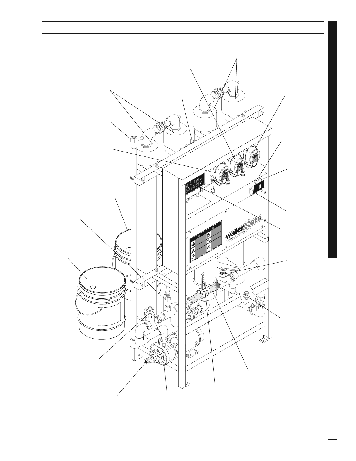
COMPACT COAG COMPONENT IDENTIFICATION
98015060-2
ORP SENSOR
Ph SENSOR
RISK OF INJUR
Y—
P
R
O
TECTIVE
EYEWEAR AND
CL
O
THING MUST
BE WORN.
when
ope
r
ating this ma
-
chin
e
.
PR
O
TE
J
ASE LOS OJOS CU
-
ANDO se opere este equip
o
.
DES LUNETTES DE SECURITE
DOIVENT ETRE POR
TEES
lorsque
v
ous operez cet appareil.
WARNIN
G
PREC
A
UCION /
AVE
R
TISSEMENT
T
O REDUCE
THE
RISK OF INJU
R
Y
READ OPER
A
T
OR’S
MAN
U
AL
CAREFUL
L
Y
BEFORE USING
.
THIS M
A
CHINE
T
O
BE USED ONL
Y BY
QU
ALIFIED
OPER
ATORS.
LEA EL MAN
U
AL OPERA
CION AN
-
TES D
E USARSE. ESTE EQ
UIPO
DEBE SER USADO SOLAMENTE
POR OPERADORES CALIFICA
-
DOS.
LIRE LE MANUEL DE
L’OP E R
A
TEUR AV
ANT UTILISA
-
TION
.
CET AP
P
AREIL DOIT ETRE
UT
I
LISE PAR DES
OPERA
T
EUR
S
Q
UAL
IF
IES.
RIESGO DE ELECT
R
OCUCIÓN
— Conecte el enchu
f
e en un con
-
tacto adecuad
o
.
Mantenga todas
las connecciones secas y arr
iba del
suel
o
.
No rocie componentes eléct
r
i-
co
s
.
Desconecte la cor
r
iente eléct
r
ica
antes de dar se
rvicio.
RIS
Q
UE D’ELECTR
OCUTION
— Relier à des pr
ises
a
v
ec mise à la
terre seulement
.
T
ous les fils doi
v
ent
être mainte
nus secs et étre suspen-
du
s
.
No jamais projeter de l’eau sur
les composantes et fils élect
r
iques
.
Couper l’alimentatation élect
r
ique
a
v
ant de faire une répar
ation.
RISK OF
ELECT
R
OCUTION
.
Connect only to
prope
r
ly g
rounded
outlet
.
K
eep all con
-
nections d
ry and off
the
g
round
.
K
eep
sp
r
a
y
a
w
a
y from
elect
r
ical wi
r
ing
and components
.
Disconnect from
elect
r
ical supply
be
fore se
r
vicing.
RISK OF
INJECTION OR
SEVERE INJU
R
Y
TO PERSONS.
Keep clear of
nozzle
.
H
O
T DISCHARGE
FLUID
.
Do not touch or
direct discharge
stream at persons.
RIESGO DE PENETRA
CIÓN O
LESIONES SEVERAS A PERSO
-
NAS.
Manténgase fue
r
a del alcance
de boquilla.
DESCA
RGA DE
A
GU
A CALIENTE
A A
LT
A PRESION
—
No toque ni
di
r
ija el flujo del agua a ot
r
as perso
-
na
s
.
RIS
Q
UE DE BLESSURES.
Se tenir
loin des
buses
.
E
A
U CHA
UDE SOUS PRESSION A
LA SORTIE
— Ne pas dir
iger le jet
d’eau
v
ers des personne
s
.
SPR
A
Y GUN
KICKS
B
A
CK
.
Hold with both
hand
s
.
LA PIST
OLA SE MUEVE CON LA
PRESIÓN
— Sostenga con las dos
manos
.
LA POIGNEE PIS
TOLET RE
-
POUSSE
—
Tenir à deux main
s
.
RISK OF INJU
R
Y—
H
O
T SUR
F
A
CES
CAN C
A
USE
B
URNS
.
Use only designed
g
r
ipping areas of
sp
r
a
y gun and w
and.
SUPERFICIES CALIENTES
— Use solamente las áreas
aisladas del gatillo y la lanza.
SUR
F
A
CES CH
A
UDES
—
T
oucher seulement les pa
r
ties
isolées des poignée pistolets et
lance
s
.
8.940-047.0
L
OW
LI
Q
UI
D
PU
M
P
O
N
STO
P
R
U
N
9.
8
07-59
7.0
ON
OFF
Flow Control
Gate Valve
Mixing
Tubes
Mixing
Tubes
Low Liquid
Indicator Light
Power
Indicator
Light
Power
Switch
CoAg+
Chemical
Bucket
Sample Spout
(used for taking samples)
EC+
Chemical
Bucket
CoAg+ Peristalic
Chemical Injector
Pump
EC+ Peristalic
Chemical Injector
Pump
Clear
Observation
Tube
Pressure Sensor
1 psi
pH Controller
(Optional)
Outlet Connection
Pump Inlet
Connection
In-Feed Pump
& Plumbing
Flow Meter
pH Peristalic
Chemical Injector
Pump (Optional)
ph Flow Switch
(Optional)
ph Sensor
(Optional)
Shown with Options
Run
Switch
Water Maze Compact CoAg • 9.801-506.0-D
DEALER MANUAL WATER TREATMENT SYSTEM
14
98015060-16
OR
P
SENS
OR
P
h
SEN
S
O
R
RISK
O
F
I
NJ
URY—
P
R
O
TECTIV
E
E
YEW
E
A
R
AND
CL
O
THING
MUS
T
B
E
W
ORN
.
when
op
e
r
at
in
g
thi
s
ma
-
chin
e
.
P
RO
T
E
J
ASE
LOS
OJO
S
C
U-
A
N
D
O
s
e
o
per
e est
e
equip
o
.
DES LUNETTES
D
E
SECURI
TE
DOIV
ENT
E
T
R
E
PO
RTEES
lorsq
ue
v
o
us o
p
e
r
e
z ce
t appareil.
WARN
IN
G
PRECA
UCION /
A
VE
R
TISSEMENT
T
O
R
E
DU
CE
T
HE
R
IS
K OF
I
NJU
R
Y
REA
D
O
PER
A
T
OR
’S
M
AN
U
AL
C
A
R
EFUL
L
Y
BEFORE
U
S
I
NG
.
T
HIS
M
A
C
H
I
N
E
T
O
BE
USE
D
ON
L
Y BY
Q
U
A
L
IFIED
OP
E
R
A
T
ORS.
LEA EL MA
NU
A
L
OP
ER
A
C
I
ON AN-
TES
D
E
USAR
SE.
ES
T
E
E
Q
UIPO
DEBE
SE
R
USADO
S
OL
A
M
E
N
T
E
P
O
R O
PERA
DORE
S
CAL
I
F
I
C
A
-
DOS
.
LIRE L
E
MANU
E
L
D
E
L
’OPER
A
TEUR
AV
A
N
T
U
T
ILIS
A
-
TION
.
CE
T AP
P
AR
E
I
L D
OIT
ET
R
E
U
T
ILIS
E P
A
R
DES
OPE
R
A
T
EUR
S
Q
UAL
I
F
IE
S
.
R
I
ESGO
D
E
E
LEC
T
R
O
C
U
C
I
Ó
N
—
Con
ec
t
e
e
l
e
nc
h
u
f
e
en
un
con
-
ta
c
to
ade
c
u
ad
o
.
M
an
t
e
ng
a
todas
la
s c
onne
c
c
i
o
ne
s sec
as
y ar
r
ib
a del
su
e
l
o
.
No rocie com
p
on
ent
es
e
l
éctr
i
-
co
s
.
D
esco
ne
c
t
e l
a
c
o
r
r
i
en
te
e
léctr
ica
a
n
t
e
s
d
e dar
se
r
vici
o
.
RI
S
Q
UE
D’
E
LECT
R
OCUTI
ON
— Relier à d
es p
r
i
se
s
a
v
ec mise
à
la
t
e
r
re
seu
le
ment
.
T
ou
s les fils
d
o
i
v
e
n
t
êt
re main
t
e
n
u
s sec
s et é
t
re
s
u
spe
n
-
d
u
s
.
N
o
jam
a
is projeter de l’
eau
su
r
l
e
s
c
ompo
san
t
e
s
e
t fi
l
s él
e
ct
r
iqu
e
s
.
C
o
uper l’
alimen
t
ata
tion él
ect
r
i
que
a
v
a
n
t
de
faire
une
r
épa
r
ation.
RISK
O
F
E
L
ECT
R
OCUTION
.
C
o
n
ne
c
t
o
n
l
y
t
o
p
rop
e
rly
g
rou
nd
e
d
o
utl
et
.
K
e
e
p al
l
c
o
n
-
n
e
ction
s
d
r
y a
nd o
f
f
t
he g
ro
u
nd
.
K
ee
p
s
p
ra
y
a
w
a
y from
e
lect
r
i
c
al
w
i
r
i
n
g
a
n
d
compon
ent
s
.
Disconn
ect
f
r
o
m
e
lect
r
i
c
al
s
uppl
y
be
f
o
re
se
r
v
i
cing.
R
I
SK OF
I
N
J
ECTION OR
S
E
V
E
R
E
I
NJ
U
R
Y
T
O
P
E
RSONS.
K
e
ep
cle
a
r of
nozzl
e
.
H
O
T DISC
HARGE
FLUI
D
.
D
o
not touch
o
r
direct discha
rge
s
tr
ea
m
at
pe
r
s
o
n
s.
RIESGO
D
E
PENETR
A
CIÓ
N O
LE
S
I
ONE
S
SE
V
ERAS
A
P
ER
S
O
-
NAS
.
Manté
n
ga
se
f
u
e
ra del alc
an
c
e
de
b
oq
u
i
ll
a
.
DE
SCARG
A
D
E
A
G
U
A CAL
IENTE
A A
LT
A
P
RES
I
O
N
—
No
toq
ue
n
i
di
r
ija e
l
fl
u
jo de
l ag
u
a
a
ot
r
as p
e
rso
-
n
a
s
.
R
I
S
Q
UE DE
BLES
S
URES
.
Se
ten
i
r
loin des
b
u
s
e
s
.
E
A
U
C
H
AUDE
S
OU
S
PRE
SSI
ON
A
LA
S
O
R
TIE
—
Ne pas di
r
i
g
e
r
le
j
e
t
d
’e
au
v
e
r
s
de
s
p
e
rs
onn
e
s
.
S
P
R
A
Y GU
N
KI
CK
S
B
A
CK
.
Hold with
b
oth
h
a
nds
.
LA P
IST
O
LA SE
M
UEVE
CON LA
PRESI
Ó
N
—
Sosteng
a c
o
n
las
d
o
s
m
a
no
s
.
L
A POIGN
E
E
P
IS
T
O
L
E
T
R
E
-
P
O
USSE —
Teni
r
à
deux
mai
n
s
.
R
I
S
K
O
F I
NJU
R
Y
—
H
O
T S
U
R
F
A
CES
CAN
C
A
U
SE
B
U
R
NS
.
Use onl
y
d
e
s
igned
g
rip
ping areas of
sp
r
a
y
g
un a
nd
w
an
d.
SUPE
RF
I
CIES CALI
E
N
T
E
S
— Use sol
ame
n
te las ár
ea
s
a
islada
s
d
e
l
ga
tillo
y
la lan
z
a.
S
U
R
F
A
C
E
S
C
H
A
UDES
—
T
o
ucher s
eu
l
eme
nt
les pa
r
t
ies
i
sol
é
es
d
e
s p
o
i
g
né
e
p
i
sto
l
e
ts
et
l
a
n
ce
s.
8
.
9
4
0-
0
47.0
L
O
W
LI
Q
UI
D
P
UM
P
O
N
S
T
O
P
R
U
N
ON
OFF
Sample Spout
(used for taking samples)
Inlet from
Pretreatment
System
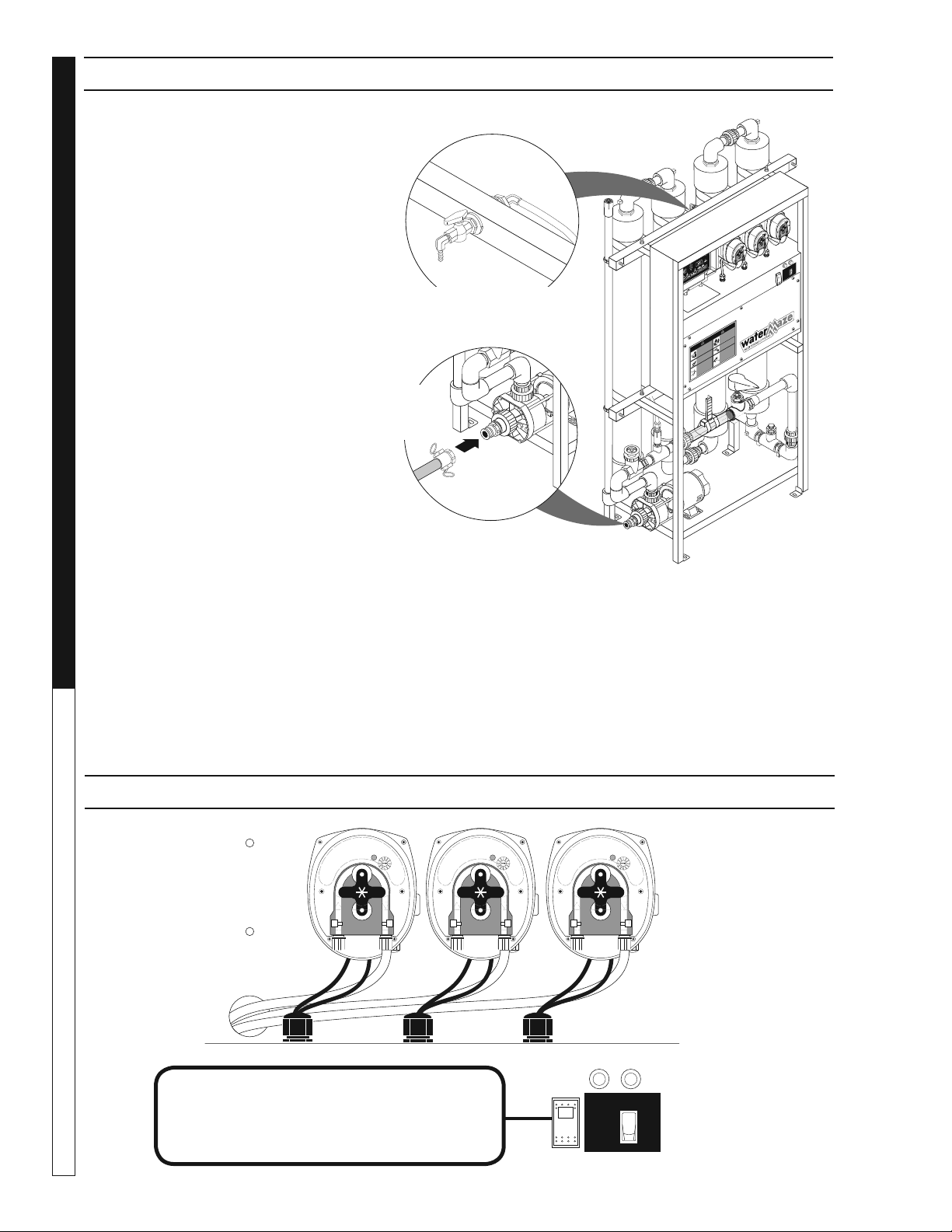
COMPACT COAG+ SYSTEM
CoAg+ System
Inlet from pretreatment pit system or tank
✧ NOTE: Flooded suction is most desirable.
When drawing water up from a pit, a foot
valve (check valve) may be required.
✧ NOTE: Cam lock (male and female) supplied with system.
Typical pretreatment considerations may include:
✧ Settling of heavy solids
✧ Removal of free fl oating oils
✧ pH adjustment
Outlet to Indexing Paper Filter or another dewatering device.
✧ Cam lock (male and female) supplied with system
✧ Hose (1.5 inch dia) is not included.
CONTROL PANEL VIEW
Shown with Options
Hold “ON” to bypass pressure
switch initial set-up.
LOW
LIQUID
PUMP
ON
STOP
RUN
9.807-597.0
98015060-18
I
ON
OFF
O
Water Maze Compact CoAg • 9.801-506.0-D
15
WATER TREATMENT SYSTEM
DEALER MANUAL
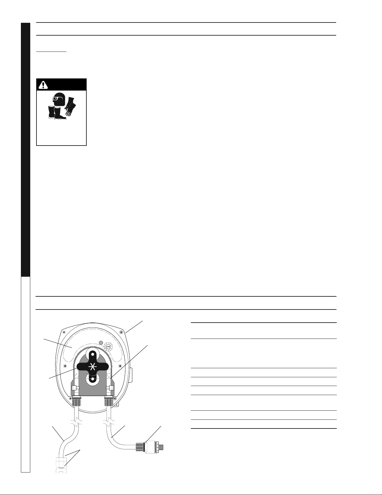
(Variable Speed Peristaltic)
TECHNICAL INFORMATION
Materials:
Squeeze Tubing Special synthetic rub ber
Strainer and
Injection Point Fitting PVC
Feed Rate: 1-7 or 8-45 GPD
Tubing Size: 1-7 or 8-45 GPD
Dimensions: Height = 5"
Width = 4"
Depth = 4 1/4"
Standard Accessories Provided with Pump:
• Squeeze Tubing
• Check Valve Assembly
• Strainer with weight
• Bulkhead fi tting with elbow
Electrical Rating:
• 20-265 VAC
• 7 W
• 50/60 Hz
Maximum System Pressure: 45 PSI
INSTALLATION
1. SUCTION TUBING: Take the 5 ft. length of 1/4"
O.D. tubing in clud ed, measure and cut the lengths
needed to run from pump head to the chemical
tank. Cut the tubing ends square.
Indicator Light
Cover
Screws
Pump Rollers
2. CONNECT SUCTION TUBING TO PUMP: Re-
move compression fi tting. Feed tube through fi t-
ting. Push end of the tube on fi tting. Tighten fi tting
fi rmly.
NOTE: To soften the end of the tubing, im merse it
in hot water.
3. CONNECT SUCTION TUBING TO STRAINER:
In stall strainer so it’s off the bottom of the chemi-
cal con tain er. Cut the suction tub ing to the length
need ed. Put weight on tubing. Push strainer end
into tubing.
METERING PUMP
OPERATION
If not already done, put the end of the suction tub ing
into the chemical container, near the bottom.
Move the “ON-OFF” switch to ON.
PRIME: To prime the pump and lines push the 3-way
switch to full speed.
FEED ADJUSTMENT: (ONLY A QUALIFIED WATER
MAZE SERVICE TECH NI CIAN SHOULD MAKE THIS
AD JUST MENT.) The feed adjustment is under the
cover plate. Remove the plate and turn the adjusting
screws clockwise to in crease feed or counterclockwise
to decrease feed.
METERING PUMPS
Chemical
Container
Suction
Tube
Discharge
Tube
Check Valve
Speed
Adjustment
Power
Cord
Strainer
Inlet
Squeeze
Tube
Speed
Adjusting
screw with
Indexing
Mark
On-Off-Full
Speed Switch
(right or left
side)
Discharge
1 2
Strainer
End
Weight
Suction
Tube
Water Maze Compact CoAg • 9.801-506.0-D
DEALER MANUAL WATER TREATMENT SYSTEM
16
DANGER: DO NOT AT TEMPT TO USE CHEM-
I CALS WITH OUT CON SULT ING YOUR CHEM I CAL
DEAL ER OR CHEM I CAL SUP PLI ER. READ MSDS
BEFORE HANDLING.
CAUTION: Wear pro tec tive
gloves, gog gles, and oth er
adequate pro tec tion for the
chem i cal haz ard.
Before re plac ing the pump head,
remove chemical from tub ing as
follows:
1. Remove strain er from chem i-
cal tank.
2. Run pump un til all chem i cal is re moved from the
tub ing.
FILL THE CHEMICAL TANK: To avoid run ning out,
of chemical, fol low a regular sched ule of mon i tor ing
chem i cal supply. Also inspect and clean the strain er
by fl ushing with a compatible liq uid, as need ed.
INSPECT SQUEEZE TUBING: Inspect tub ing regu-
larly and re place it if it is deteriorating.
REPLACE SQUEEZE TUB ING:
1. Remove compression fi ttings from the tubing at
the pump head.
2. Pull the suction and dis charge tub ing from the
pump head.
3. Remove the front cover from the pump.
4. Rotate the pump rollers to a vertical position.
5. Lift the inlet fi tting out of the housing.
6. Pull the tube out while rotating the pump rollers
clockwise.
7. Remove the outlet fi tting.
8. Install the inlet fi tting for the new tube assembly.
9. Press the tube into place in front of a roller while
rotating the roller assembly clockwise.
10. Install the outlet fi ttings.
11. Reconnect the suction and discharge lines.
12. Install the front cover.
CAUTION: DO NOT LOSE THE BEAR ING FROM
THE CEN TER HOLE IN THE BACK COVER.
TUBE REPLACEMENT:
Clear or transparent plas tic tubing should be re placed
at least every three months if ex posed to the sun.
Replace tubing yearly if feeder is in stalled indoors.
INSPECT FOR LEAKAGE:
Inspect the chemical system daily for any signs of leak-
age. If leaking occurs at tubing connections, tighten fi t-
ting compression nut fi nger tight. If leakage con tin ues,
re move pressure from the system. Disconnect the
tub ing, trim ends square and reconnect.
INSPECT FOR BLOCKED FLOW:
Precipitates or other chemical reactions cause in-
jec tion points to clog. If the type of chemical being fed
elim i nates the use of fl ushing solution, the injection
point must be in spect ed at regular intervals. Strainers
must be kept clean with periodic back-fl ush ing.
WARNING
PROTECTIVE
EYEWEAR AND
CLOTH ING MUST
BE WORN.
ITEM PART NO. DESCRIPTION QTY
1 8.749-856.0 Pump, Peristaltic, PRS-1,
1-7 gpd 2
2 8.749-862.0 Tube, Squeeze, Santoprene,
*
PR-7, 8-45 gpd 1
8.749-864.0 Tube, Squeeze, Santoprene,
*
PRS-1, 1-7 gpd 1
3 8.749-860.0 Check Valve, PVC 1
4 8.749-857.0 Tubing, 1/4", PE, Black AR
5 8.749-863.0 Strainer, w/Weight 1
6 8.711-737.0 Tubing, 1/8" , ID,
Norprene AR
7 8.751-801.0 Faceplate, PRS-1/PR-7 1
8 8.751-376.0 Roller Assembly, PRS-1 1
* Alternative tubing materials are available
1
2
3
6
4
7
8
5
METERING PUMP AND PARTS LIST
METERING PUMP MAINTENANCE
Water Maze Compact CoAg • 9.801-506.0-D
17
WATER TREATMENT SYSTEM
DEALER MANUAL
CENTRIFUGAL PUMP
Your centrifugal pump has been quality-built and engi-
neered to give you effi cient, dependable service. It is
equipped with union connectors to make installation
and future service easier.
The advanced design uses a single speed motor which
reduces operation and maintenance to simple, com-
mon-sense procedures.
PUMP OPERATION
(Infeed Pump)
WARNING
RISK OF ELECTRIC
SHOCK: USE
CAUTION WHEN
HANDLING.
WARNING: Do not touch pumps,
pump motors, water or dis-
charge piping when the pumps
are connected to electrical
power. Do not handle a pump or
pump motor with wet hands or
when standing on a wet or damp
surface or in water. Never touch
a pump or discharge piping
when a unit is operating or fails
to operate. Always disconnect the pump cord
(power) before handling.
1. The shaft seal depends on water for lubrication.
Do not operate the pump unless there is water. Dry
running (pump not pumping water) will cause seal
damage and eventual pump failure.
2. The motor is equipped with an automatic reset
thermal protector. This means if the temperature in
the motor should rise unduly, the switch will cut off
all power before damage can be done to the motor.
When the motor has cooled suffi ciently, the switch
will reset automatically and restart the motor. If the
protector trips repeatedly (cycling on protector) the
pump should be removed and checked as to the
cause of the diffi culty. Low voltage, long extension
cords, clogged impeller, very low head or lift, etc.,
could cause cycling. Cycling of the protector will
cause eventual motor burnout.
INFEED PUMP MAINTENANCE
WARNING
RISK OF ELECTRIC
SHOCK: USE
CAUTION WHEN
HANDLING.
WARNING: Before attempting to
service, disconnect power from
unit. Do not handle the pump
with wet hands or when stand-
ing on a wet or damp surface or
in water. Failure to follow pre-
cautions can result in personal
injury and /or property damage.
NOTE: Only qualifi ed electricians
or servicemen should attempt to repair this unit. Im-
proper repair and/or assembly can cause an electrical
shock hazard.
1. Bearings in this unit are pre-lubricated. No
additional lubrication is necessary.
2. Cleaning - Occasionally clean the Transfer pit and
pump if dirt or foreign matter accumulate. Small
stones, gravel, sand, dirt, silt, etc. can clog and dam-
age the pump and pump seal, eventually causing
pump failure.
3. Disassembly of the motor prior to expiration of the
warranty will void the warranty. It may also cause
internal leakage and damage to the unit. If repairs
are required, return the pump to a local service
station or return to dealer.
4. If the motor has been disassembled or the switch
chamber opened after the warranty expiration
date, the O-rings and gaskets must be replaced.
Care must be taken to assure that the seals, the
switch cover and air tube gaskets do not leak.
5. The pump should be checked for proper opera-
tion weekly or monthly by watching the operation
of the pump. If anything has changed since the
pump was new, the pump should be examined,
and repaired if necessary.
OPERATION AND MAINTENANCE
Water Maze Compact CoAg • 9.801-506.0-D
DEALER MANUAL WATER TREATMENT SYSTEM
18
CONFIGURING AND TUNING PERISTALTIC PUMPS
The following is a set of guidelines to be used when
confi guring the peristaltic pumps that inject Coag and
EC chemicals into the WaterMaze water treatment
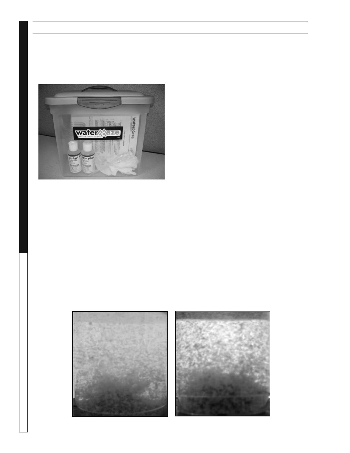
system. Materials required for this process are included
in the WaterMaze CoAg Test Kit. Materials include:
• Small quantity (4oz ea) of CoAg+ and EC+ chemi-
cals to be used in system
• 500 ml capacity test sample containers
• Clean standard sized plastic transfer pipettes
(20 drops/ml, 3.2 ml draw)
• Filter Paper (50, 20 and 5 micron)
Determining Required
Chemical Concentrations:
1. Obtain a representative water sample of the
waste stream (1-2 gallons).
NOTE: Sampling is highly important. The sample
should be representative of what will be processed
by the CoAg treatment system. In other words,
proper pretreatment should be applied to remove
heavy solids (e.g., those that settle quickly within
say 10 to 15 minutes) and to remove free oils (e.g.,
oils that can be skimmed from the surface of the
water).
2. Pour a 500 ml sample into a clear container
(beaker, cup, etc.)
3. Test the pH of the sample.
4. Adjust pH to 6.5 to 8. In many cases, pH adjust-
ment should be considered as part of the pretreat-
ment process. Adjusting the pH may allow for
additional separation of oils and solids.
5. Add 2 drops (.1 ml) of CoAg+ coagulant to the
sample.
6. Mix vigorously for at least 45 seconds.
7. Observe the reaction noting the start of coagula-
tion (clumping together of solids).
8. Add 3 drops (.15 ml) of EC+ polymer and gently
mix (slowly) for 30 seconds.
9. If successful, a separation of the solids should
occur with the majority of the solids falling to the
bottom of the sample container with clear phase
of liquid on the top of the sample.
10. This sample can then be fi ltered through 50
micron paper to remove the fl occulated solids.
11. If a separation does not occur, repeat the above
steps with a new sample and add one additional
drop (.05 ml) of CoAg+. Unsuccessful results
after further adjustments may indicate that a dif-
ferent treatment technology is required other than
Chemical treatment.
Water before (left) and after EC polymer is added to increase clumping.
Water Maze Compact CoAg • 9.801-506.0-D
19
WATER TREATMENT SYSTEM
DEALER MANUAL
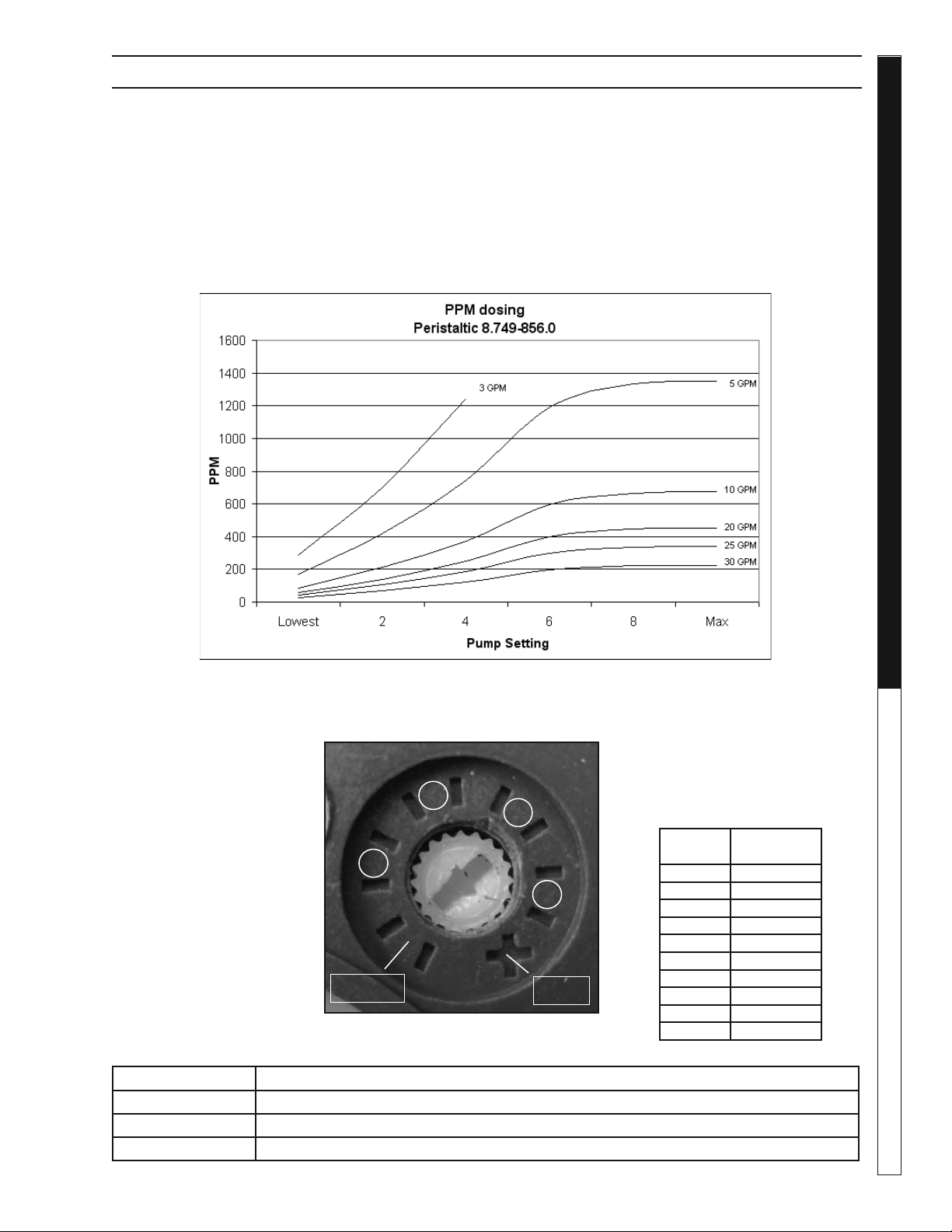
CONFIGURING AND TUNING PERISTALTIC PUMPS
Figure 1. Peristaltic pump dial.
This fi gure is a reference for
the pump settings determined
from the above chart . The dial
in the image is currently at the
“Lowest” setting.
Table 1. PPM concentration per
drop of chemical. To be used
with 20drops/ml transfer pipets
and 500 ml of sample water.
# of
Drops
PPM of
Chemical
1 100
2 200
3 300
4 400
5 500
6 600
7 700
8 800
9 900
10 1000
2
8
4
6
Lowest
Max
Calibrating Peristaltic Pumps:
1. Collect the ppm concentration values for the Coag
and EC polymer injections. Use the chart on the
last page to determine the correct setting for each
peristaltic pump. Align the ppm requirements with
the desired processing rate, in gallons per minute
(GPM), and obtain an estimate for the pump set-
ting from the continuum along bottom of the fi gure.
2. The pump settings reference the spaces between
hash marks on the pump’s fl ow rate adjustment
dial. Figure 1 on the last page shows the notation
for these markings. A small screw driver can be
used to adjust the pump to match the setting that
was estimated by the confi guration chart.
Number of Drops Observation
Pump Confi guration Chart for WaterMaze Coag/EC Water Treatment System.
Lowest
Max
4
6
8
2
Water Maze Compact CoAg • 9.801-506.0-D
WATER TREATMENT SYSTEM
Troubleshooting Guide
20
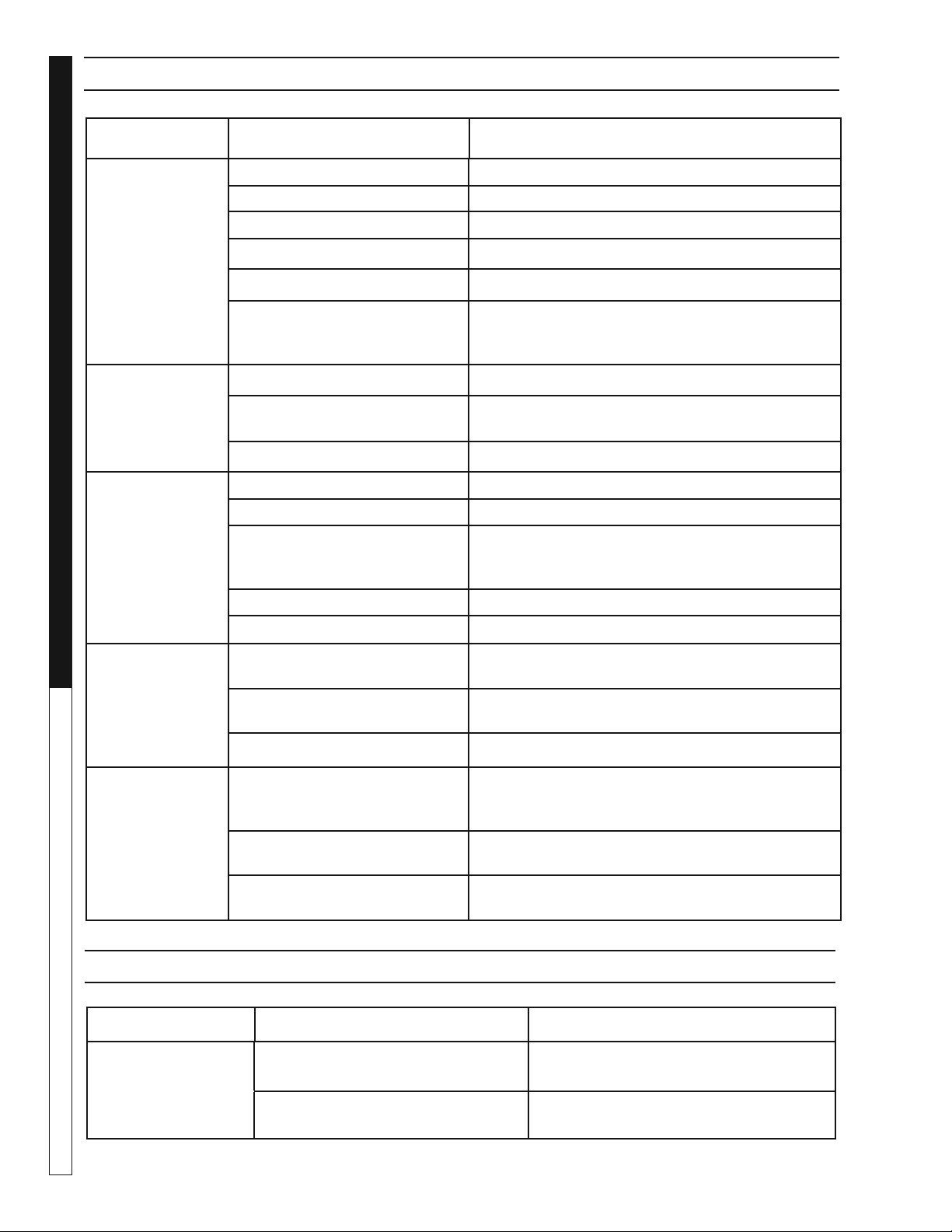
TROUBLESHOOTING - PUMP
PROBLEM POSSIBLE CAUSE SOLUTION
PUMP
DOES NOT
TURN ON
Circuit breaker shut "OFF Turn "ON" circuit breaker.
Accumulation of trash on fl oat Clean fl oat.
Float obstruction Check fl oat path and provide clearance.
Defective switch Have pump serviced by authorized service center.
Defective motor Have pump serviced by authorized service center.
Low line voltage If voltage under recommended minimum, check
size of wiring from main switch on property.
If OK, contact power company.
PUMP
WILL NOT
SHUT OFF
Float obstruction Check fl oat and fl oat rod path. Provide clearance.
Pump is air locked
(Infeed Pump)
Shut power off for approximately 1 minute, then
restart. Repeat several times to clear air from pump.
Defective fl oat switch Disconnect switch, check with ohmmeter.
PUMP
RUNS BUT
DOES NOT
DISCHARGE
LIQUID
Lift too high for pump Check rating table.
Inlet to impeller plugged Pull pump and clean.
Low line voltage If voltage under recommended minimum, check
size of wiring from main switch on property.
If OK, contact power company.
Clogged impeller Remove housing, unclog.
Faulty motor protector Replace pump.
PUMP
DOES NOT
DELIVER
RATED
CAPACITY
Low voltage, speed too slow Check for proper supply voltage to make
certain it corresponds to nameplate voltage.
Impeller or discharge pipe is
clogged
Pull pump and clean. Check pipe for scale or
corrosion.
Impeller wear due to abrasives Replace worn impeller.
PUMP
CYCLES
CONTINUALLY
Low line voltage If voltage under recommended minimum, check
size of wiring from main switch on property.
If OK, contact power company.
Worn or defective pump parts
or plugged impeller
Replace worn parts or entire pump.
Clean parts if required.
Pump air locked Turn pump "ON" and "OFF" several times.
Fill hose manually with water.
PROBLEM POSSIBLE CAUSE SOLUTION
INFEED PUMP
DOES NOT
OPERATE
Sump or pre-treatment tank has low
water level
Raise level in sump or pre-treatment
tank.
Control panel pump switch is in the
OFF position
Confi rm that control panel pump switch is
in the ON position.
TROUBLESHOOTING - INFEED PUMP
Water Maze Compact CoAg • 9.801-506.0-D
21
WATER TREATMENT SYSTEM
Troubleshooting Guide
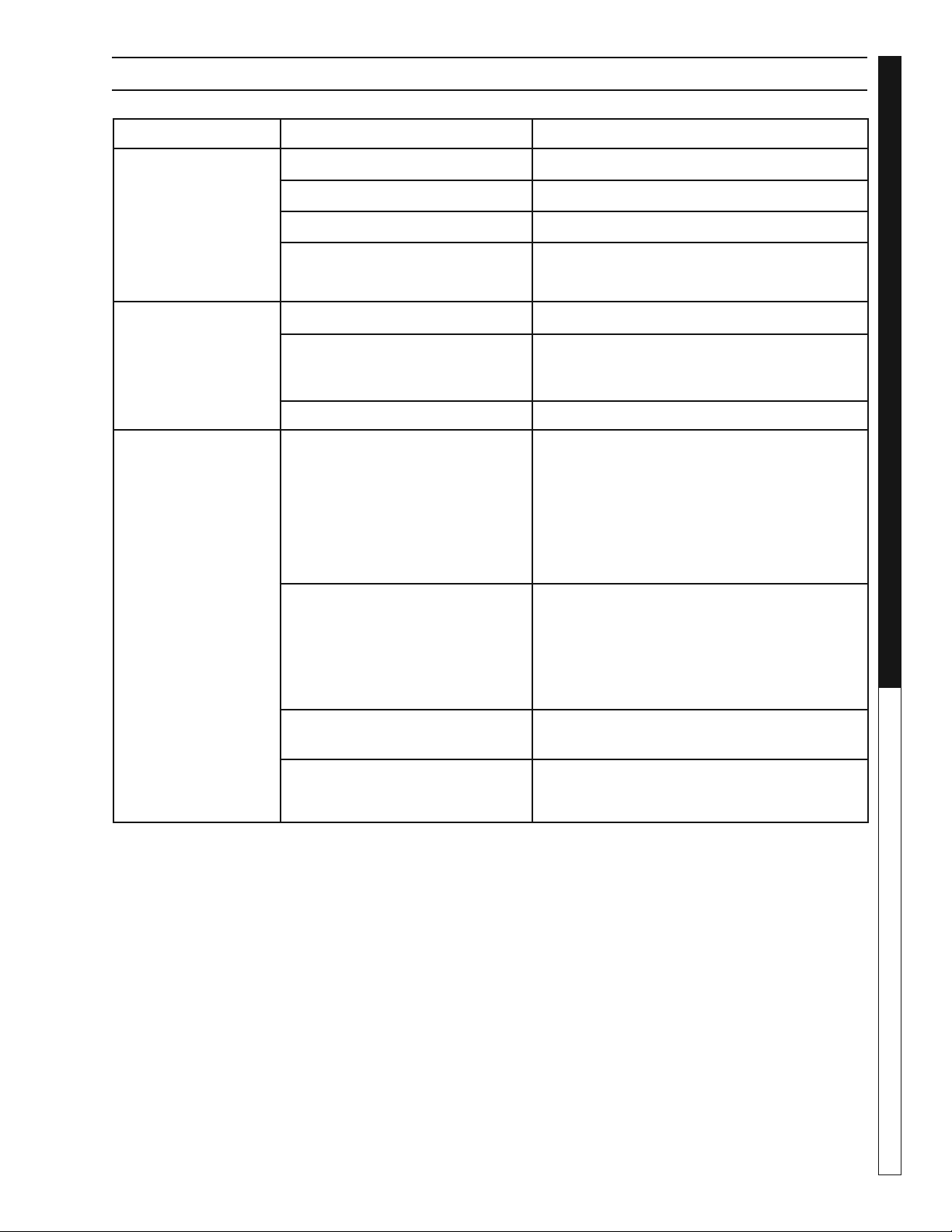
TROUBLESHOOTING - PUMP MOTOR
PROBLEM POSSIBLE CAUSE SOLUTION
MOTOR
WILL
NOT RUN
Disconnect switch is "OFF" Be sure switch is on.
Breaker is tripped Reset breaker.
Starting switch is defective Replace starting switch.
Wires at motor are loose,
disconnected or wired incorrectly
Refer to instructions on wiring.
Check and tighten all wiring.
MOTOR
RUNS HOT
AND OVERLOAD
KICKS OFF
Motor is wired incorrectly Refer to instructions on wiring.
Voltage is too low Check with power company. Install heavier
wiring if wire size is too small. See wiring
instructions.
Defective fl oat switch Disconnect switch, check with ohmmeter.
MOTOR
RUNS BUT
NO WATER
IS DELIVERED
Pump in a new installation did
not pick up prime through:
a. Improper priming a. Re-prime (3 or 4 times may be needed)
by stopping and starting motor several
times.
b. Air leaks b. Check all connections on suction line.
Pump has lost its prime through:
a. Air leaks a. Check all connections on suction line, air
volume control, jet and shaft seal
b. Water level below suction of
pump
b. Lower suction line into water and
re-prime.
Check valve is stuck in closed
position
Replace check valve
Pipes are frozen Thaw pipes. Bury pipes below the frost line.
Heat pipes below frost line. Heat pit or pump
house.
Water Maze Compact CoAg • 9.801-506.0-D
WATER TREATMENT SYSTEM
Troubleshooting Guide
22
PROBLEM POSSIBLE CAUSE SOLUTION
VALVE
LEAKS
WHEN "OFF"
Dirt or debris on diaphragm
seat
Clean diaphragm seat.
Solenoid not fully closed after
manual operation
Turn solenoid clockwise to fully seated
position.
Solenoid O-ring damaged or
twisted
Turn off water, inspect O-ring.
Reseat if twisted, replace if damaged.
Diaphragm damaged Turn off water, remove bonnet screws and
inspect diaphragm for nicks or damage NOTE:
Diaphragm has one bleed hole molded into it.
Replace, if necessary, with diaphragm kit.
Dirt interfering with solenoid
operation
Turn off water, remove solenoid and fl ush
seating surface in bonnet and at bottom of
solenoid with water.
Solenoid damaged Turn off water supply and replace solenoid.
WATER
WON'T
SHUT OFF
Valve in manual "ON" position Turn solenoid clockwise to "OFF" position.
Diaphragm bleed hole blocked Use Manual Flush Mode. Turn water supply
"OFF" and immediately back "ON" to clear
blockage. If still blocked, turn off water and
inspect diaphragm looking for blockage.
Damaged solenoid Turn off water supply and replace solenoid.
LOW OR
INADEQUATE
FLOW CONDITION
Gate valve not fully open Open gate valve fully.
Pipeline blockage Clear pipeline.
VALVE WON'T
TURN ON
ELECTRICALLY
No power to solenoid Make sure solenoid has power.
Low voltage Check for proper voltage to unit.
No water pressure Make sure water pressure is available to valve.
Turn off water, without cutting wires, unscrew
and swap solenoids between valves. Turn on
water and test again. If problem stems from
the solenoid, replace solenoid.
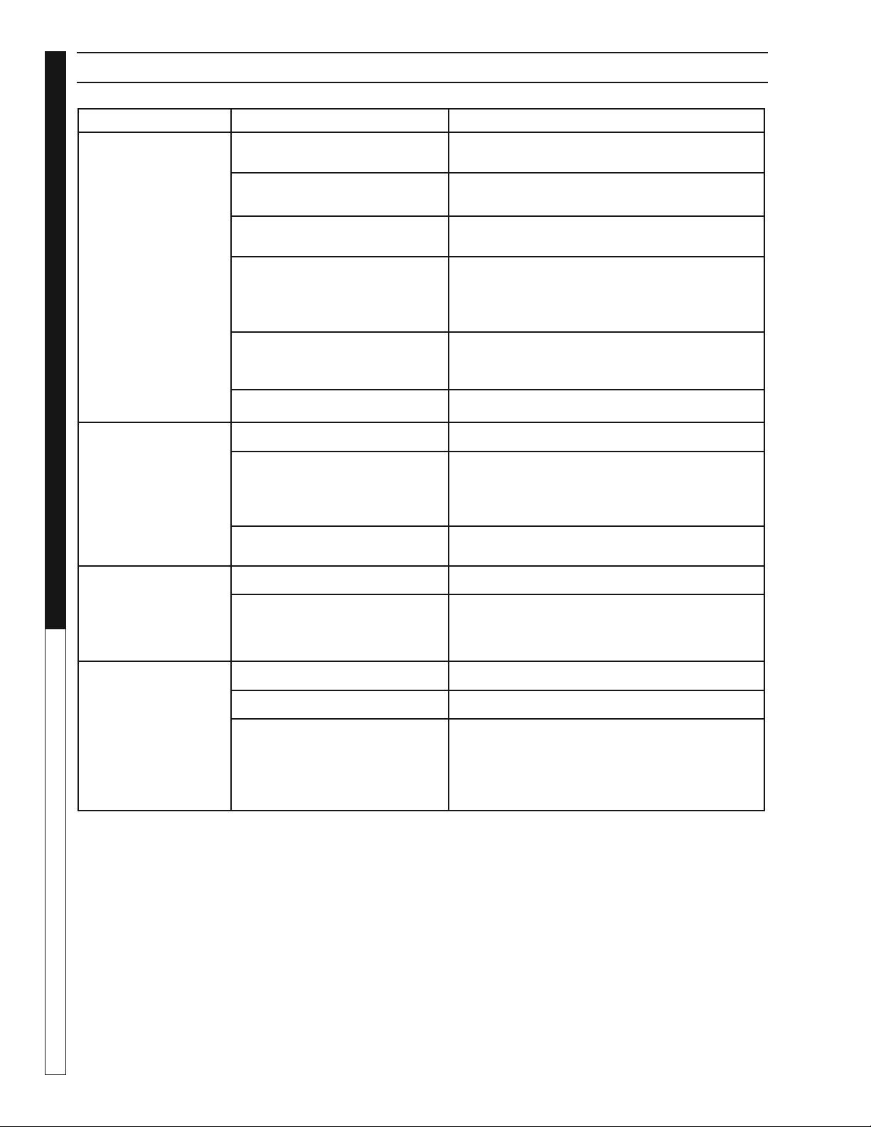
TROUBLESHOOTING - WATER SOLENOID

Water Maze Compact CoAg • 9.801-506.0-D
23
WATER TREATMENT SYSTEM
Troubleshooting Guide
PROBLEM POSSIBLE CAUSE SOLUTION
CRACKED
OR BROKEN
STATIONARY
SEAT (CERAMIC)
Seal ran dry and heated up.
When liquid reached seal
faces it was cooler, causing
thermal cracks
Check to insure seal chamber is full of liquid
before starting pump. On high temperature ap-
plication insure proper fl ushing at seal faces.
CARBON WASHER
SCORED AND
GROOVED
Dirty system Have system cleaned and fl ushed. Consider
use of Tungsten Carbide or Silicon Carbide
Rings.
CARBON WASHER
WORN UNEVENLY
Seal improperly installed Check installation instructions for proper as-
sembly.
BUNA DIAPHRAGM
HARD OR BRITTLE.
RAPID CARBON
WEAR.
Air leak on suction side of
pump
Check cover gasket, hand knobs, hose, clamps,
etc. Replace or tighten as necessary.
DIAPHRAGM
SOFT AND STICKY;
APPEARS TO
BE DISSOLVING.
Bellows not compatible with
material being pumped
Consult dealer for recommendation advising of
pumpage and temperature.
TROUBLESHOOTING - WATER SEALS
Water Maze Compact CoAg • 9.801-506.0-D
DEALER MANUAL WATER TREATMENT SYSTEM
24
98015060-3
To Mixing
Tube
PUMP & PLUMBING EXPLODED VIEW
17
2
1
3
18
10
15
24
9
4
11
27
12
15
8
24
26
13
Shown with Options
25
3
2
3
2
15
16
23
28
29
5
5
5
6
6
6
6
7
7
7
21
20
19
7
14
31
30
34
32
33

Water Maze Compact CoAg • 9.801-506.0-D
25
WATER TREATMENT SYSTEM
DEALER MANUAL
PUMP & PLUMBING PARTS LIST
ITEM PART NO. DESCRIPTION QTY
1 8.750-270.0 Fitting, Comp 1-1/2" S x 1-1/2"
MBT, Blk 1
2 8.706-367.0 Pipe, 1.5", PVC 80, 3" 3
3 8.706-374.0 Elbow, 1.5", S x S
PVC 80, 90° 3
4 8.707-344.0 Valve, PVC, 1-1/2" Slip x Slip
Gate 1
5 8.706-409.0 Adapter, 1" MT x Slip, PVC 80 3
6 8.706-398.0 Bushing, 1" FIPT x 1-1/2" SP
PVC 80 4
7 8.706-366.0 Pipe, 1", PVC 80, 2" 5
8 8.750-189.0 Flow Switch, 1" SCH 40 1
9 8.706-469.0 Union, 1-1/2" Slip x Slip
PVC 80-, SPEA 1
10 8.706-360.0 Pipe, 1-1/2" PVC Clear, 6" 1
11 8.706-426.0 Tee, 2" x 2" x 1/2" SCH 80 1
12 8.706-406.0 Bushing, 1/2" x 1/2" SPGXFT
PVC 80, SPEARO 1
13 8.716-156.0 Switch, Pressure
PM11120A-1PF, 1-PSI 1
14 8.706-914.0 Bushing, 1/2" x 1/8" Pipe 1
15 8.706-373.0 Elbow, 1", S x S, PVC 80, 90° 3
16 8.706-597.0 Union, 1", S x S, PVC 80
Spears 1
17 8.917-759.0 Pump, 3/4HP, 115V
Center Discharge 1
18 8.707-169.0 Adapter, 1-1/2" x Male x 1-1/2"
Male Third C 1
19 8.706-432.0 Tee, 1" FPT x Slip x Slip
PCV 80 1
20 8.706-928.0 Bushing, 1" x 1/2"
Blk Poly Reducer 1
21 8.706-387.0 Plug, 1/2" MIPT, PVC 80 1
22 8.706-367.0 Pipe, 1-1/2" PVC, 80, 7" 1
23 8.706-366.0 Pipe, 1", PVC 80, 10" 1
24 8.706-366.0 Pipe, 1", PVC 80, 6.5" 1
25 8.706-366.0 Pipe, 1", PVC 80, 3" 1
26 8.706-393.0 Coupling, 1/2", PVC Pipe
SCH 80, TXT 1
27 9.802-514.0 Strain Relief, LT, Str, 1/2 NPT
.23-.45D 1
28 8.712-136.0. Gauge, Flowmeter, 1-1/2" 1
29 8.716-157.0 Protector, Pressure Switch 1
30 8.706-422.0 Hanger, Pipe, 1 1/4' Click #40 2
31 8.718-947.0 Screw, #14 X 1", Tek, SS 2
32 8.719-528.0 Bolt, 3/8" x 1" NC, Blk 4
33 9.802-807.0 Washer, 3/8" SAE, Flat Zinc 4
34 9.802-779.0 Nut, 3/8", ESNA, NC 4
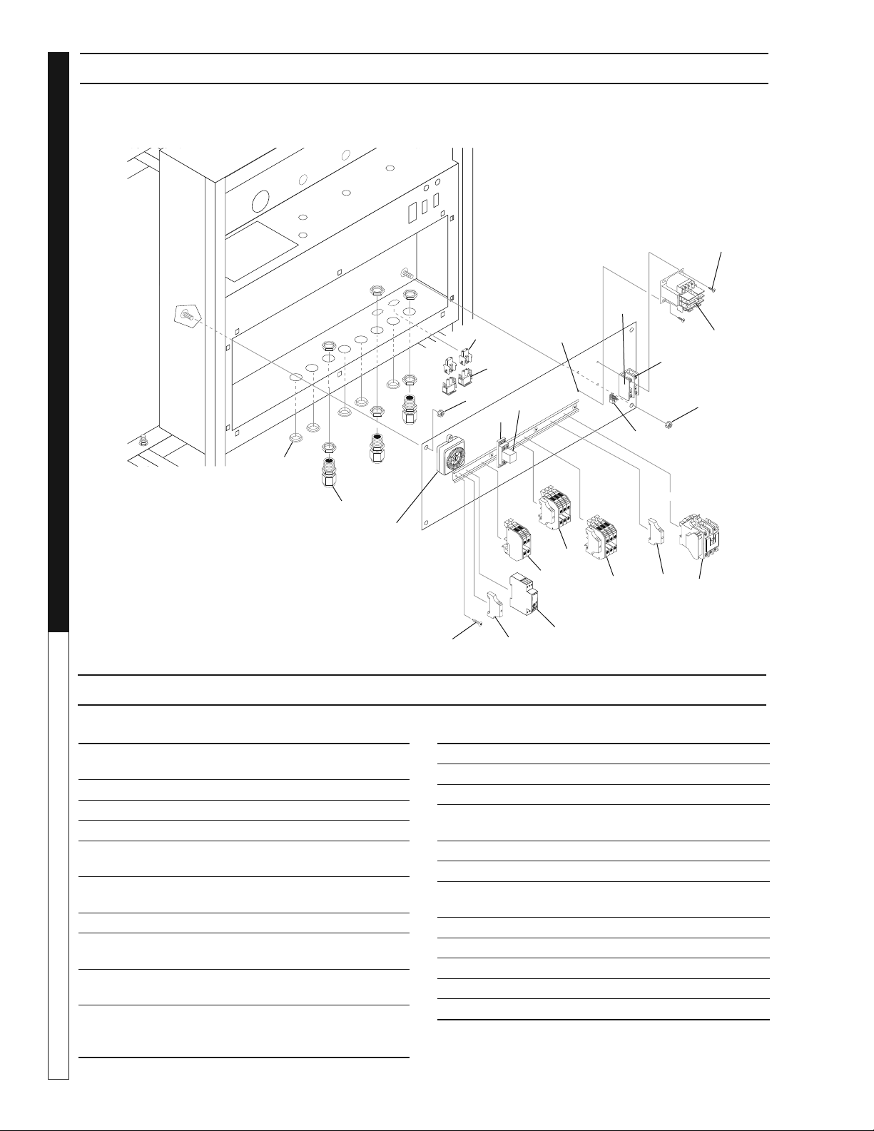
Water Maze Compact CoAg • 9.801-506.0-D
DEALER MANUAL WATER TREATMENT SYSTEM
26
98015060-6
ITEM PART NO. DESCRIPTION QTY
1 8.752-153.0 Relay, 24VDC,
RH2B-ULDC24V, IDEC 1
2 9.802-467.0 Base, Relay, SH2B-05, IDEC 1
3 9.802-457.0 DIN Rail, 35mm 1
4 9.802-105.0 Plug, 7/8', Hole 5
5 9.802-514.0 Strain Relief, LT, Str, 1/2 NPT,
.23-.45 D 5
6 9.803-663.0 Fuse, KTK-R2(amp) 600V
Midget Fuse 2
7 8.713-078.0 Fuse, 2 Amp FNM-2 1
8 9.804-595.0 End Bracket, (Standard) 4
AMC Option 6
9 9.802-553.0 Transformer
120-24V 0.050KVA 1
10 8.716-396.0 Terminal Block, ENTRELEC
115-116-07M4/6 (Standard) 6
AMC Option 9
ITEM PART NO. DESCRIPTION QTY
11 8.724-269.0 Contactor, DP, 25 Amp 1
12 8.921-705.0 Stand Off PH Stand 1
13 9.802-778.0 Nut, 5/16" Whiz Loc Flange 4
14 8.751-306.0 Timer, Multi Function
AMC Option 1
15 9.802-793.0 Nut Cage, 1/4" X 16 GA 3
16 8.718-936.0 Screw, #8 x 1/2" 11
17 8.716-253.0 Timer, 24 Hour Pin
AMC Option 1
18 8.716-121.0 Power Block, 1 Pole 1
19 8.716-120.0 Power Block, Adder 1
20 8.716-460.0 Terminal, Grounding Lug 1
21 8.716-317.0 Plug, Housing 2
22 8.716-318.0 Housing, Cap 2
ELECTRICAL BOX PARTS LIST
ELECTRICAL BOX EXPLODED VIEW
4
2
13
21
5
11
16
12
8
8
10
9
16
17
14
13
20
10
10
19
1
22
18
Shown with Options
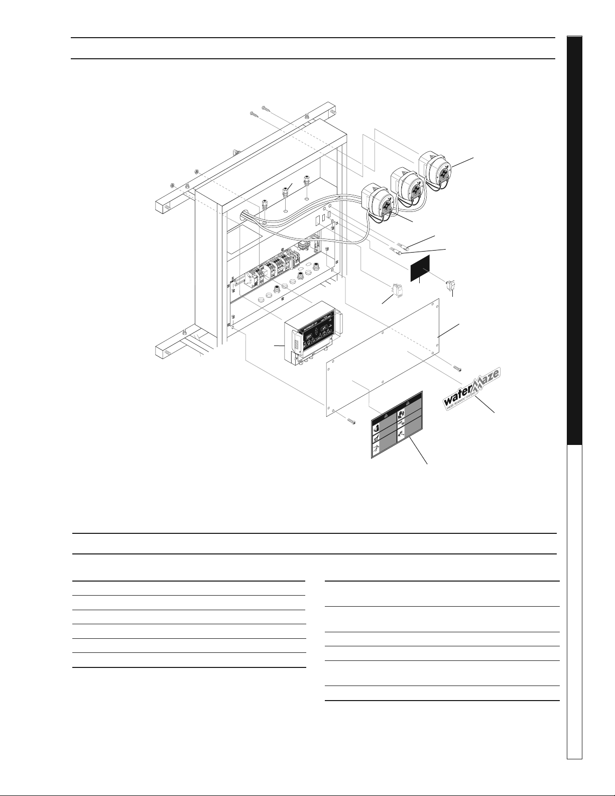
Water Maze Compact CoAg • 9.801-506.0-D
27
WATER TREATMENT SYSTEM
DEALER MANUAL
98015060-7
RISK OF INJUR
Y—
PRO
TECTIVE
EYEWEAR AND
CL
O
THING MUST
BE
W
ORN
.
when
ope
r
ating this ma
-
chin
e
.
P
R
O
TE
J
ASE LOS OJOS CU
-
AND
O se opere este equip
o
.
DES LUNETTES DE SECURITE
DOIVENT ETRE PO
R
TEES
lorsque
v
ous operez cet appareil.
WARNING
PRECA
UCION /
A
VER
TISSEMENT
T
O REDUCE
THE
RISK OF INJUR
Y
READ OPERA
T
OR’S
MAN
UAL
CAREFUL
LY
BEFORE USING
.
THIS M
A
CHINE
TO
BE USED ON
L
Y BY
Q
U
ALIFIED
OPERA
T
ORS.
LEA EL MAN
U
AL OPER
A
CION AN
-
TES DE USARSE
.
ESTE EQUIPO
DEBE SER USADO SOLAMENTE
POR OPERADORES CALIFICA
-
DOS.
LIRE LE MANUEL DE
L’OPER
A
TEUR
AVANT UTILISA-
TION.
CET AP
PAREIL DOIT ETRE
UT
I
LISE PAR DES
OPERA
TEUR
S
Q
UAL
IF
IES
.
RIESGO DE ELECTROCUCIÓN
— Conecte el enchu
f
e en un con
-
tacto adecuado
. Mantenga todas
las connecciones secas y arr
iba del
suel
o
. No rocie componentes eléct
r
i
-
co
s
.
Desconecte la cor
r
iente eléct
r
ica
antes de dar se
r
vici
o
.
RIS
QUE D’ELECT
R
OCUTION
— Relier à des p
r
ises
a
v
ec mise à la
terre seulement
.
Tous les fils doi
v
ent
être mainte
n
u
s secs et étr
e suspen
-
du
s
.
No jamais projeter de l’ea
u sur
les composantes et fils élect
r
i
que
s
.
Couper l’alimentatation élect
r
ique
a
v
ant de
f
aire une réparation.
RISK OF
ELECT
ROCUTION
.
Connect only to
prope
r
ly
g
rounded
outlet
.
K
eep all con
-
nections d
r
y and off
the
g
round.
K
eep
sp
ra
y awa
y from
electr
ical wi
r
ing
and component
s
.
Disconnect from
electrical supply
be
f
ore se
r
vicing.
RISK OF
INJECTION OR
SEVERE INJU
R
Y
TO PERSONS.
K
eep clear of
nozzle
.
H
O
T DISCHARGE
FLUID
.
Do not touch or
direct discharge
stream at person
s
.
RIESGO DE PENETR
A
CIÓN O
LESIONES SEVERAS A PERSO
-
NAS. M
a
nténgase fue
r
a del alcance
de boquilla
.
DESCARGA DE
A
G
U
A CALIENTE
A A
LT
A PRESION
—
No toque ni
di
r
ija el flujo del agua a ot
ras perso-
nas
.
RIS
Q
UE DE BLESSURES.
Se tenir
loin des
buse
s.
E
A
U CH
A
UDE SOUS PRESSION A
LA SOR
TIE
— Ne pas di
r
iger le jet
d’eau
v
ers des personne
s
.
SPR
AY GUN
KICKS
B
ACK.
Hold with both
hand
s
.
LA PIS
TOLA SE MUEVE CON LA
PRESIÓN
— Sostenga con las dos
mano
s
.
LA POIGNEE PIS
T
OLET RE
-
POUSSE
—
Tenir à deux main
s
.
RISK OF INJUR
Y—
H
OT SUR
F
A
CES
CAN C
A
USE
B
URNS
.
Use only designed
g
r
ipping areas of
sp
r
a
y gun and
w
and.
SUPERFICIES CAL
IENTES
— Use solamente las áreas
aisladas del gatillo y la lanza.
SUR
FA
CES CHA
UDES
—
Toucher seulement les par
ties
isolées des poignée pistolets et
lance
s
.
8.940-047.0
L
O
W
ST
OP
RU
N
9.8
07-59
7.0
LOW
LI
QU
I
D
PU
M
P
ON
ST
O
P
R
U
N
9.
8
07
-
597
.
0
O
N
O
FF
1
2
3
4
ITEM PART NO. DESCRIPTION QTY
1 8.749-856.0 Pump, Peristaltic, 1-7 GPD 2
2 8.900-803.0 Label, Watermaze, Logo Small 1
3 9.800-347.0 Label, Warning 1
4 9.802455.0 Light, Indicator, Green 125V 1
5 9.803-650.0 Light, Indicator, Blue 28V 1
6 9.802-451.0 Switch, Rocker, Carling Green 1
ITEM PART NO. DESCRIPTION QTY
7 9.802-514.0 Strain Relief, LT, Str
1/2 NPT,.23-.45D 3
8 9.807-597.0 Label, Control Panel
Compact CoAg 1
9 8.716-989.0 Controller w/Probe 1
10 9.921-708.0 Cover, Panel 1
11 8.749-855.0 Pump, Peristaltic, 8-45 GPD
(pH Option) 1
12 9.802-453.0 Switch, Curvette 1
CONTROL PANEL PARTS LIST
CONTROL PANEL EXPLODED VIEW
5
7
8
6
9
10
Shown with Options
11
12
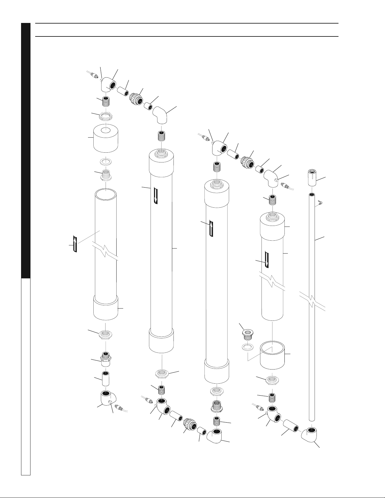
Water Maze Compact CoAg • 9.801-506.0-D
DEALER MANUAL WATER TREATMENT SYSTEM
28
MIXING TUBE ASSEMBLY EXPLODED VIEW
1
2
1
3
3
2
4
4
4
4
5
5
5
5
6
6
6
6
6
5
5
8
8
8
8
7
7
15
9
9
9
7
7
7
10
10
10
7
11
18
17
13
14
Shown with Options
15
7
15
7
15
15
15

Water Maze Compact CoAg • 9.801-506.0-D
29
WATER TREATMENT SYSTEM
DEALER MANUAL
MIXING TUBE ASSEMBLY PARTS LIST
ITEM PART NO. DESCRIPTION QTY
1 8.730-407.0 Pipe, 4" Dia, ABS Black, 4' 4
2 9.800-343.0 Label, Flow Arrow Up
Blue Outline 2
3 9.800-344.0 Label, Flow Arrow Down
Blue Outline 2
4 8.730-410.0 Cap, Flat, 4' Slip, Black ABS 8
5 8.706-484.0 Bulkhead, 1", Polypro 8
6 8.706-439.0 Nipple, PVC 80, Close 7
7 8.706-378.0 Elbow, 1" Slip x FPT
PVC 80, 90° 8
8 8.706-366.0 Pipe, 1", PVC 80
3" Length 4
9 8.706-366.0 Pipe, 1", PVC 80, 2" Length 3
10 8.706-597.0 Union, 1", S x S, PVC 80
Spears 4
11 8.706-373.0 Elbow, 1" S x S PVC 80, 90° 1
12 8.706-366.0 Pipe, PVC 80, 2" Length 2
13 8.706-444.0 Adapter, Female,1" Slip x FT 1
14 8.706-366.0 Pipe, 1", PVC 80, 55" Length 1
15 9.802-035.0 Plug, 1/8" Square Head, Blk 6
16 8.706-366.0 Pipe, 1" PVC 80, 3" Length 1
17 8.706-398.0 Bushing, 1 FIPT x 1-1/2"
SP, PVC 80 1
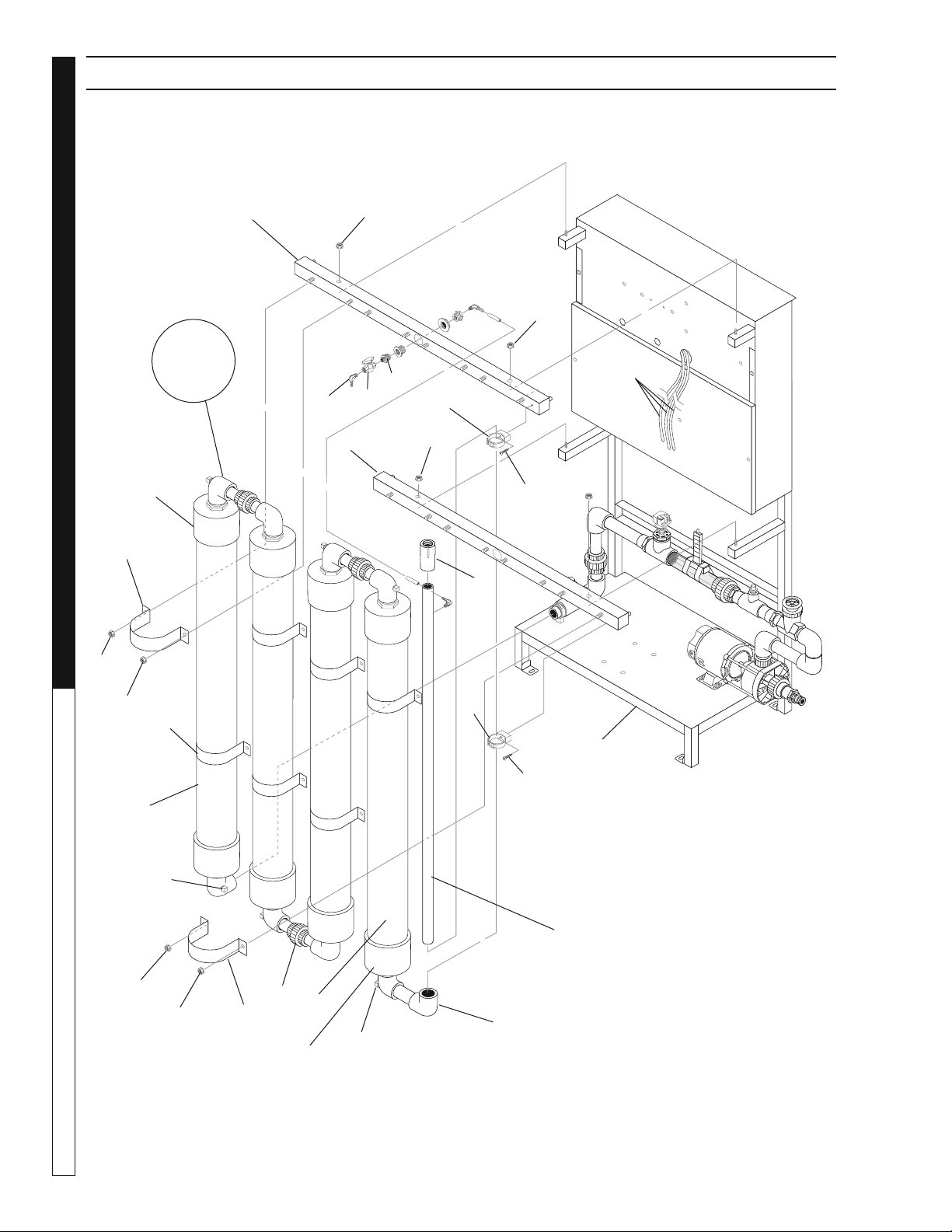
Water Maze Compact CoAg • 9.801-506.0-D
DEALER MANUAL WATER TREATMENT SYSTEM
30
98015060-5
3
2
11
14
15
12
11
10
16
16
17
17
1
4
4
4
5
5
6
6
6
6
7
7
9
13
13
EC+
Injection
Site
From
Peristaltic
Pumps
ASSEMBLY EXPLODED VIEW
For
Details See
Mixing Tube
Assy
CoAg+
Injection
Site
7
Shown with Options

Water Maze Compact CoAg • 9.801-506.0-D
31
WATER TREATMENT SYSTEM
DEALER MANUAL
ASSEMBLY PARTS LIST
ITEM PART NO. DESCRIPTION QTY
1 8.706-588.0 Connector, 3/8' x 1/4',
Male Elbow, POL 3
2 8.707-321.0 Valve, Ozone Meter, 1/4' PLAS 1
3 8.706-587.0 Nipple, 1/2' x 1/4', HEX 1
4 9.802-775.0 Nut, 1/4" Flange, ZN 4
5 8.916-873.0 WLMT, Brace, Stealth Tube 2
6 9.802-778.0 Nut, 5/16" Whiz Loc Flange 20
7 8.916-867.0 Bracket, Stealth Tube 8
8 8.706-366.0 Pipe, 1" PVC 1
9 8.706-597.0 Union, 1" , S x S, PVC 80
Spears 4
10 8.913-227.0 Stand, Welded ASSY, PH 1
11 8.730-407.0 Pipe. 4" DIA, ABS Black 4
12 8.706-373.0 Elbow, 1" S x S PVC 80, 90° 2
13 8.730-410.0 Cap, Flat, 4' Slip, Black ABS 8
14 8.706-366.0 Pipe, 1', PVC 80, 55" Length 1
15 8.706-444.0 Adapter, Female,1" Slip x FT 1
16 9.802-798.0 Screw, # 10 x 1/2", TEK
HEX Head 3
17 8.706-423.0 Hanger, Pipe,1' Click # 32 2
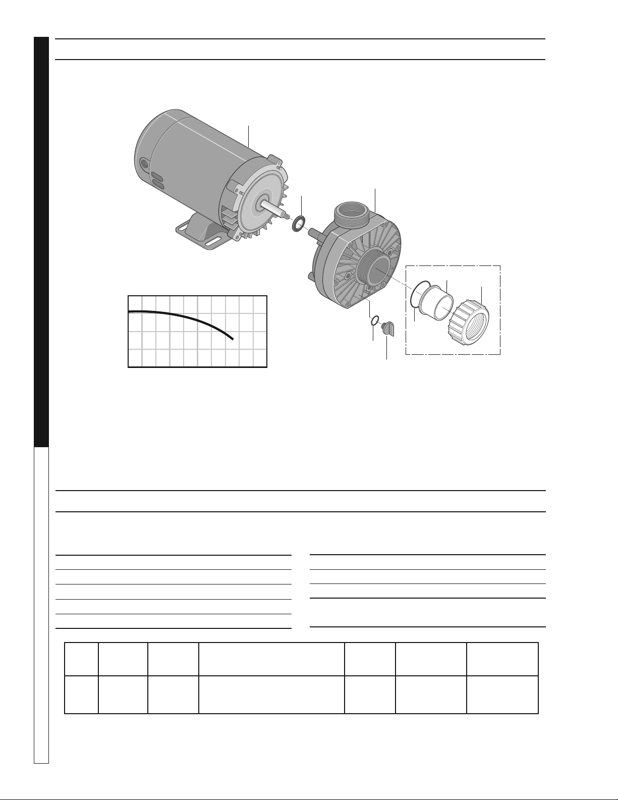
Water Maze Compact CoAg • 9.801-506.0-D
DEALER MANUAL WATER TREATMENT SYSTEM
32
INFEED PUMP EXPLODED VIEW
ITEM PART NO. DESCRIPTION
QTY
1 8.726-025.0 Motor, 3/4 HP, 115V 1
2 NA Slinger 1
3 8.726-024.0 Pump, 3/4 HP, Wet End 1
4 NA Drain Plug 1
5 NA O-Ring, Drain Plug 1
HP Volts Phase
Size
Inlet Outlet
Running
Amps
Max.
Pressure
Max.
Water Temp.
3/4 230V 1 1-1/2" FPT/ 1-1/2"FPT/
1-1/2" MBT 1-1/2" MBT
10.0 40 PSI 104°F/40°
ITEM PART NO. DESCRIPTION
QTY
6 NA O-Ring 1
7 NA Adapter, Union 1-1/2” Slip 1
8 NA Collar, Union 1
Kit:
6-8 8.750-270.0 Fitting, Compression, 1-1/2" Slip 2
Part # 8.917-759.0
OZONE PUMP EXPLODED VIEW PARTS LIST
40
20
0
20 40 60 80
U.S. GALLONS PER MINUTE
TOTAL HEAD IN FEET
1
2
3
4
5
6
7
8
Not Included
With Pump

Water Maze Compact CoAg • 9.801-506.0-D
WATER TREATMENT SYSTEM
WARRANTY
LIMITED NEW PRODUCT WARRANTY
WASH WATER / WATER TREATMENT SYSTEMS
WHAT THIS WARRANTY COVERS
All
WATER MAZE
water treatment systems are warranted by to the original purchaser to be free from defects in materials
and workmanship under normal use, for the periods specified below. This Limited Warranty, subject to the exclusions shown
below, is calculated from the date of the original purchase, and applies to the original components only. Any parts replaced
under this warranty will assume the remainder of the part’s warranty period. A 60 day grace period will be given for installa-
tion.
ONE YEAR PARTS AND 30 DAY LABOR WARRANTY:
All components excluding normal wear items as described below.
WARRANTY PROVIDED BY OTHER MANUFACTURERS:
Motors, which are warranted by their respective manufacturers, are serviced through these manufacturers’ local authorized
service centers.
WATER MAZE
cannot provide warranty on these items.
WHAT THIS WARRANTY DOES NOT COVER
This warranty does not cover the following items:
1. Normal wear items, such as seals, filters, gaskets, O-rings, packings, pistons, brushes, filtering media, ozone
bulbs, sensors, UV scanners, oil-skimmer belt, impedance sensor. Minor leaks covered first time on original start-
up only.
2. Damage or malfunctions resulting from accidents, abuse, modifications, alterations, incorrect installation, improper
servicing, failure to follow
manufacturer’s maintenance instructions, or use of the equipment beyond its stated
usage specifications as contained in the operator’s manual.
3. Damage due to freezing, sludge build-up, chemical deterioration (oxidation, chloride or fluoride corrosion), and
rust.
4. Damage to components from fluctuations in electrical or water supply.
5. Normal maintenance service, including adjustments.
6. Transportation to service center, field labor charges, or freight damage.
7. Consumables and water quality.
WHAT YOU MUST DO TO OBTAIN WARRANTY SERVICE
While not required for warranty service, we request that you register your
WATER MAZE
Product by returning the com-
pleted registration card. In order to obtain warranty service on items warranted by
WATER MAZE
, you must return the
product to your Authorized
WATER MAZE
Dealer, freight prepaid, with proof of purchase, within the applicable warranty
period. If the product is permanently installed, you must notify your Authorized
WATER MAZE
Dealer of the defect. Your
Authorized
WATER MAZE
Dealer will file a claim with
WATER MAZE
, who must subsequently verify the defect. In most
cases, the part must be returned to
WATER MAZE
freight prepaid with the claim. For warranty service on components
warranted by other manufacturer’s, your Authorized
WATER MAZE
Dealer can help you obtain warranty service through
these manufacturers’ local authorized service centers.
LIMITATION OF LIABILITY
WATER MAZE’S
liability for special, incidental, or consequential damages is expressly disclaimed. In no event shall
WATER MAZE’S
liability exceed the purchase price of the product in question.
WATER MAZE
makes every effort to ensure
that all illustrations and specifications are correct, however, these do not imply a warranty that the product is merchantable
or fit for a particular purpose, or that the product will actually conform to the illustrations and specifications. Our obligation
under this warranty is expressly limited at our option to the replacement or repair at a service facility or factory designated
by us, of such part or parts as inspection shall disclose to have been defective. THE WARRANTY CONTAINED HEREIN
IS IN LIEU OF ALL OTHER WARRANTIES, EXPRESS OR IMPLIED, INCLUDING ANY IMPLIED WARRANTY WATER
QUALITY, MERCHANTABLIITY OR FITNESS FOR A PARTICULAR PURPOSE ARE EXPRESSLY LIMITED TO THE
DURATION OF THIS WARRANTY.
This warranty gives you specific legal rights and you may also have other rights which
vary from state to state.
WATER MAZE
does not authorize any other party, including authorized
WATER MAZE
Distributors,
to make any representation or promise on behalf of
WATER MAZE
, or to modify the terms, conditions, or limitations in any
way. It is the buyer’s responsibility to ensure that the installation and use of
WATER MAZE
products conforms to local
codes. While
WATER MAZE
attempts to assure that its products meet national codes, it cannot be responsible for how the
customer chooses to use or install the product. Some states do not allow limitations or exclusion or limitation of incidental or
consequential damages, so the above limitation or exclusion may not apply to you.

Form #9.801-506.0 • Printed in U.S.A.