OPERATOR’S MANUAL
For the dealer nearest you, consult our web page at www.wmaze.com
■ REC2-20 Water Treatment System
8.917-436.0 - E11/29/17
WARNING:
This product and accessories may contain a chemical known to the State of
California to cause cancer and birth defects or other reproductive harm.
For more information about this regulation: www.P65Warnings.ca.gov
Patent Pending
Se
nDEC
T
AC
H/HO
UR
1
/
1
0
89174360-1

Part Number ______________________________
Serial Number _________________________ Code ________
Date of Purchase ___________________________
The part and serial numbers will be found on a decal attached to
the machine. You should record both serial number and date of
purchase and keep in a safe place for future reference.
CONTENTS
2
Water Maze REC2-20 • 8.917-436.0 - E
Introduction and Important Safety Issues ............................................3-4
Application and Intended Use .................................................................5
Installation & Operating Instructions .......................................................6
Pressure Switch and Pressure Tank Operation .......................................7
Maintenance Instructions ........................................................................8
Rec2-20 Component Identifi cation ..........................................................9
Piping Connection Diagram ..................................................................10
Float Connection Diagram ....................................................................11
Digital Timer Instructions ..................................................................12-13
Operation and Maintenance ..................................................................14
Troubleshooting Guides ...................................................................15-19
Body Exploded View and Parts List .................................................20-21
Cabinet Exploded View and Parts List .............................................22-23
Electrical Box Exploded View and Parts List ....................................24-25
Control Panel Exploded View & Parts List.............................................26
Junction Box Exploded View and Parts List ..........................................27
Right Side Panel Exploded View and Parts Lists .............................28-29
Plumbing Exploded View and Parts List ...........................................30-31
Transfer/Ozone Pump Exploded View and Parts List .......................32-33
Junction Box wiring diagram..................................................................34
Ozone Generator Maintenance, Exploded View & Parts List ...........35-38
Warranty Accessories and Parts
Warranty Water Treatment Systems Warranty
Water Maze REC2-20 • 8.917-436.0 - E
3
WATER TREATMENT SYSTEM
OPERATOR’S MANUAL
Your owner’s manual has been prepared to provide
you with a simple and understandable guide, for
equipment operation and maintenance, based on
the latest product information available at the time of
printing. To keep your machine in top running condition
follow the specifi c maintenance and troubleshooting
procedures given in this manual.
NOTE: Water Maze reserves the right to make
changes at anytime without incurring any obligations.
Owner/User Responsibility:
The owner and/or user must have an understand-
ing of the manufacturer’s operating instructions and
warnings before using this equipment. Warning
information should be emphasized and understood.
If the operator is not fl uent in English, the manufac-
turer’s instructions and warnings shall be read to and
discussed with the operator in the operator’s native
language by the purchaser/owner, making sure that
the operator comprehends its contents.
Owner and/or user must study and maintain for future
reference the manufacturers’ instructions.
SAVE THESE INSTRUCTIONS
This manual should be considered a permanent
part of the machine and should remain with it if
machine is resold.
When ordering parts, please specify model and
serial number. Use only identical replacement
parts.
This machine is to be used only by trained opera-
tors.
GENERAL SAFETY
INFORMATION
WARNING: When using this ma-
chine basic precautions should
always be followed, including
the following:
1. Read all the instructions
before using the product.
2. To reduce the risk of injury,
close supervision is neces-
sary when a product is used
near children.
3. Know how to stop the product and bleed pressures
quickly. Be thoroughly familiar with the controls.
4. Stay alert – watch what you are doing.
5. Do not operate the product when fatigued or under
the infl uence of alcohol or drugs.
6. Keep operating area clear of all persons.
7. Do not overreach or stand on unstable support.
Keep good footing and balance at all times.
8. Follow the maintenance instructions specifi ed in
the manual.
9. Know the system application, limitations, and
potential hazards.
WARNING: This machine must
be wired to the correct voltage.
Refer to the information located
on the serial plate.
WARNING: All wiring must
be performed by a qualified
electrician.
WARNING: Risk of Electric Shock
DANGER – Improper connection of the equipment-
grounding conductor can result in a risk of electro-
cution. Check with a qualifi ed electrician or service
personnel if you are in doubt as to whether this
machine is properly grounded. Have proper power
connections installed by a qualifi ed electrician.
Do not use any type of adaptor with this product.
GROUNDING INSTRUCTIONS
This product must be connected to a grounded, metal,
permanent wiring system; or an equipment-grounding
conductor must be run with the circuit conductors
and connected to the equipment-grounding terminal
located on the product in compliance with National
Electrical Codes (NEC).
GROUND FAULT CIRCUIT
INTERRUPTER PROTECTION
To comply with the National Electrical Code (NFPA
70) and to provide additional protection from the risk
of electric shock, this machine should only be con-
nected to a circuit protected by a ground fault circuit
interrupter (GFCI).
WARNING: Do not use near
concentrations of flammable
or explosive fluids such as
gasoline, fuel oil, kerosene,
solvents, etc. Do not use in ex-
plosive atmospheres. Liquids
compatible with component
materials should only be used.
Failure to follow this warning
can result in personal injury
and/or property damage.
10. The main power must be brought from the circuit
breaker and wired into the electrical box on the
Rec 2-20. This power supply must be run through
conduit in compliance with local and national
electrical codes. A power disconnect should be
located near the machine for maintenance and
emergency purposes.
WARNING
READ OPERATOR’S
MANUAL THOROUGHLY
PRIOR TO USE.
INTRODUCTION & IMPORTANT SAFETY INSTRUCTIONS
WARNING
RISK OF EXPLOSION:
DO NOT SPRAY FLAM-
MABLE LIQUIDS.
WARNING
KEEP WATER SPRAY
AWAY FROM
ELECTRICAL WIRING.
Water Maze REC2-20 • 8.917-436.0 - E
OPERATOR’S MANUAL WATER TREATMENT SYSTEM
4
11. Protect all electrical wiring from sharp objects,
hot surfaces, oil, sunlight, and chemicals. Avoid
kinking the cords.
WARNING: If any cords or electrical wires appear to
be frayed, damaged, or in poor condition, proceed
with caution and immediately take steps to have
the cords repaired or replaced.
12. Never make adjustments on the machine while it
is in operation, except for those prescribed in this
manual.
13. Follow the maintenance instructions specifi ed in
this manual.
14. Before servicing the machine, refer to all the MS-
DS’s on the material identifi ed in the waste stream.
You must comply with all warnings and wear all
protective clothing as stated on the MSDS’s.
15. Inlet water temperature must not exceed 85°F.
16. The best insurance against an accident is precau-
tion and knowledge of the equipment.
17. Water Maze is not liable for modifi cations or use
of components not purchased from Water Maze.
18. Personal Safety:
a. Wear safety glasses and
other applicable protective
clothing at all times when
working on this machine.
Refer to item #14 under
Important Safety Information.
b. Keep your work area clean,
uncluttered and properly
lighted
c. Replace all unused tools and equipment.
d. Keep visitors at a safe distance from work area.
19. Running the system without water will damage the
pumps and will void the warranty.
20. Release all pressure within the system before
servicing any component.
21. Drain all liquids from the component before
servicing.
IMPORTANT SAFETY INSTRUCTIONS
WARNING
PROTECTIVE
EYE WEAR AND
CLOTHING MUST
BE WORN.
22. Check hoses for weak or worn conditions before
each use, making certain that all connections are
secure.
23. Periodically inspect pump and system components.
Perform routine maintenance as required.
24. Do not touch an operating motor. Modern motors
are designed to operate at high temperatures.
25. Do not touch any electrical component with wet
hands, when standing on a wet or damp surface,
or in water.
26. The pump motors are equipped with a thermal
protector. Tripping is an indication of motor over-
loading as a result of operating at excessively high
or low voltage, inadequate wiring, incorrect motor
connections, or a defective motor or pump.
27. Keep machine from freezing.
28. Do not spray water directly at machine.
WARNING: This system contains moving parts in
the control center and in the pumps. Follow safe
practices when performing maintenance and when
troubleshooting. Disconnect the power before ser-
vicing this machine. If the power disconnect is out
of sight, lock it in the open position and tag it to
prevent unexpected application of power.
WARNING: Make sure to take precautions when
performing maintenance on the pump in the catch
basin. Turn off the power to the pump and make
sure electrical cords are well maintained.

Water Maze REC2-20 • 8.917-436.0 - E
5
WATER TREATMENT SYSTEM
OPERATOR’S MANUAL
Rec2-20 Water Management Unit:
The Rec2-20 water management unit should be
installed as a recycler to transport water between
a water treatment system and local storage tank.
The Rec2-20 unit can then be used to circulate and
refresh stored water. An optional Ozone genera-
tor can be added further sanitize and de-odor the
water. The Rec2-20 unit can also maintain wa-
ter levels in the local storage tank, to prevent
overfl ows and draining. Auxiliary parts are also
available for hose and pressure washers. The
Rec2-20 should be installed as a component of a
system that incorporates multiple water treatment
technologies.
To assure the safety of the Rec2-20 unit,
pretreatment of the waste water should be applied to
remove as many solids and oils as possible prior to
entering the Rec2-20.
Consult a Water Maze representative prior to
combining the Rec2-20 with other pre-treating
and post treating equipment.
TCLP Testing:
TCLP is one of the Federal EPA test methods that
are used to characterize waste as either hazardous
or non-hazardous for the purpose of disposal. TCLP
is an acronym for Toxicity Characteristic Leaching
Procedure. A TCLP test may be required prior to
disposal of your solid waste. Consult a Water Maze
representative for details.
Site Preparation:
The installation site surface should be of compacted
materials, such as concrete, asphalt or pavement
and capable of supporting the Rec2-20 treatment
system.
APPLICATION AND INTENDED USE
Water Maze REC2-20 • 8.917-436.0 - E
OPERATOR’S MANUAL WATER TREATMENT SYSTEM
6
The following instructions will provide adequate in-
formation to fully install your Water Maze Recycling
System. Please follow these instructions step by step
to ensure proper installation.
WARNING: A backfl ow preventer must be provided
when connecting to a potable water supply to pre-
vent back-siphonage into the water supply.
Equipment and Supplies Needed for
Installation
Aside from having a general assembly of tools on
hand, you will need to supply a few additional items
to complete the installation of your system.
• Forklift • Tape Measure
• Level
Equipment Installation
The model Rec2-20 water treatment system must
be installed on a level surface.
■ If surface is not level, shimming may be
required.
Installation Checklist
❑ Are all piping and electrical float switches
connected as shown on the Float piping and
Connection Diagrams pages 10 and 11.
❑ Are fl oats connected as shown on the Junction
Box wiring Diagram on page 34?
❑ Is the voltage correct?
START-UP
1. Make sure that all equipment is level.
2. Install fl oat switches in infeed/sump tank and
storage tank according to the Float Connection
Diagram, page 11, included in this manual.
3. Connect piping according to Piping Connection
Diagram, page 10, included with this manual.
4. Connect electrical power to electrical box: When
connecting to the power supply, follow all electri-
cal and safety codes as well as the most recent
National Electric Code (NEC) and Occupational
Safety and Health Act (OSHA). Ground system
before connecting to the power supply.
WARNING: All wiring must be performed by
a qualifi ed electrician.
5. Use included Digital Timer Instructions, pages
12-13, to set clock and circulation/ozonating
times.
6. Fill infeed/sump tank with water and ensure stor-
age tank's water level is above the "Low Water
Float".
7. Fill all inlet lines (two inlets from storage tank on
right side and one from infeed source on left side)
with water.
INSTALLATION & OPERATING INSTRUCTIONS
8. Open any valves between Rec2-20 module and
storage tank, infeed/sump tank, drain, and fresh
water source.
9. Press "ON" switch on control panel to begin
Rec2-20 operations. To complete priming of infeed
and circulation/ozone pumps, hold "ON" switch
down for three seconds until light begins fl ashing.
The fl ashing "ON" light indicated the machine is in
a fl ushing routine that forces fresh water through
plumbing to prime pumps. Flushing routine will
last fi fteen seconds, however, pumps will need to
continue running for approximately one minute
before they complete priming and reach capac-
ity water fl ow. If pumps do not reach a high fl ow
rate within one minute of fl ushing, repeat rountine
by holding down "ON" switch for three seconds,
again.
UTILITY USAGE
Electrical: 230 Volts, 1 PH
Amps: 21.6 amps
OPERATING ENVIRONMENT
The Rec 2-20 is designed to work in a wide variety
of operating conditions. In normal operating environ-
ments, the system should perform as specifi ed. In
extremely hot or cold environments certain precautions
need to be taken.
Operating Conditions
Air Temperature Range 40° - 120°F
Cold Weather
DRAIN SYSTEM WHEN
TEMPERATURES DROP
BELOW FREEZING
Protect the Rec 2-20 from damage
that can occur when freezing
water expands. Freezing water
may cause pipes to burst.
Drain all pipes if a prolonged hard
freeze is expected. Make sure
all valves are open so water can
completely drain from the system.
Cold Climate Conditions
In locations where freezing temperatures will be
experienced on a regular basis or where very cold
temperatures will be incurred, the water treatment
system should be drained when the outside ambient
temperature drops below freezing and/or the water
system (Rec 2-20) should be housed in a heated
structure. The warranty on the water treatment
system does not provide for repair due to freezing
conditions.
Water Maze REC2-20 • 8.917-436.0 - E
7
WATER TREATMENT SYSTEM
OPERATOR’S MANUAL
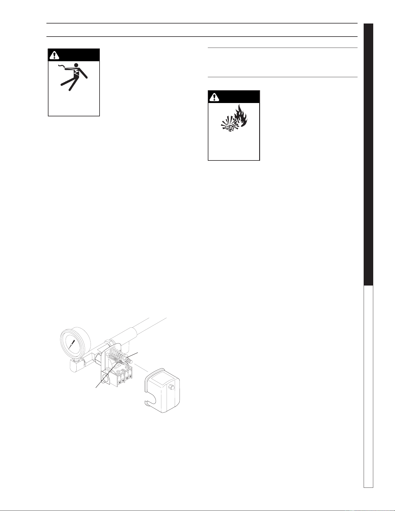
WARNING: Live electrical
contacts are exposed, so dis-
connect power fi rst and have
work performed by a qualifi ed
electrician.
Remove cover of the pump
pressure control switch to allow
access to the two nuts used to
adjust the pump operating pres-
sure. The pressure switch on Water Maze equipment
is set at the factory and should not have to be adjusted
at start-up, but will need to be verifi ed at start up and
maintained regularly at least monthly.
1. The nut on the larger spring in the pump pressure
switch, adjusts the pump cut in (cut on) and pump
cut out (cut off) pressures simultaneously.
2. The nut atop the smaller spring in the pump pres-
sure switch only controls the cut out range and
is used to narrow or widen the gap between the
pump cut in and cut out pressures.
3. To cycle the pump less frequently, the gap should
be as wide as possible while still allowing the
pump to shut off quickly when all outlets are
closed. Adjust the smaller spring to widen the
gap between pump in and out (on and off). 40-
45 PSI (CLP, Rec2-20) or 30 PSI (EC1-300A) is
desirable. Adjusting the larger spring should not
be necessary.
4. When making pressure switch adjustments, make
sure all pump outlets are off or closed, except for
the one outlet valve used to relieve and build pres-
sure while making pressure switch adjustments.
PRESSURE TANK
OPERATION
WARNING! When the tank has
been in service and a change
to a higher pre-charge pres-
sure is necessary because of a
required change in the pressure
switch setting, failure to follow
instructions below can cause a
rupture or explosion and could
cause serious or fatal personal
injury and/or property damage.
• Do not adjust or add pressure if there has been a
loss of air.
• Do not adjust the pre-charge pressure if there is
visible exterior corrosion.
• Do not adjust the pre-charge pressure if there has
been a reduction of the pump cycle time or the
pre-charge pressure compared to its initial setting.
A reduction in pump cycle time can result from
loss of tank corrosion and any re-pressurization
or additional pressure could result in rupture or
explosion.
• Pressure tank pressure is factory set but will have
to be checked regularly (at least monthly). Use
an air pressure (tire) gauge. Before checking air
pressure on the pressure tank, purge all water out
of the tank by turning the pump on and pumping
all water out of the pressure tank.
1. Our transfer pump water systems use a water
pressure tank and water pump with these two
pressure operation ranges:
Cut in (start pumping): 20 PSI
Cut out (stop pumping): 30 PSI (EC1-300A)
Cut out (stop pumping): 40-45 PSI (CLP, REC2-20)
2. Typical factory set air pressure on bladder-type
residential water pressure tanks are shipped from
the factory with a standard pre-charge of:
18 psig for models WX-101 and WX-102
18 psig for models WX-103 and WX-203
18 psig for models WX-205 and WX-350
3. Set the well tank air pressure to 2 PSI below the
pump pressure switch cut-in pressure. This is
usually 18 PSI.
WARNING
RISK OF
EXPLOSION:
FOLLOW
INSTRUCTIONS WHEN
CHANGING PRESSURE
WARNING
RISK OF
ELECTRIC SHOCK:
USE CAUTION
WHEN HANDLING.
PRESSURE SWITCH AND PRESSURE TANK OPERATION
89174360-14
Controls
Cut In/Cut Out
Controls
Cut Out Range

Water Maze REC2-20 • 8.917-436.0 - E
OPERATOR’S MANUAL WATER TREATMENT SYSTEM
8
Hot Weather
The Rec 2-20 may encounter minor problems, such as
a slight increase in odor, when operating in extremely
hot temperatures in excess of 100° F.
Environmental
To reduce deterioration of equipment it is recom-
mended that the Rec 2-20 Water Treatment System
be protected from environmental elements such as
rain, snow, hail, direct sunlight, as well as freezing
temperatures.
MAINTENANCE INSTRUCTIONS
Daily and weekly maintenance is important for your
system to function consistently and properly. Mainte-
nance frequency depends on many factors, such as
usage, volume of sludge, etc. On-site personnel should
be trained and be aware of the daily and weekly main-
tenance that is required to meet these performance
factors. We recommend the following:
Daily Schedule:
(Performed by customer personnel)
1. Become familiar with the control panel and
make sure that the electrical switch is in the ON
position. This will allow your system to operate
automatically.
2. While operating the system, observe and repair
any water leaks.
Weekly Maintenance Schedule:
(Performed by customer personnel)
1. Check pressure gauge inside of Rec2-20 to
ensure it is operating between desired
pressures of 20 and 40 psi.
2. Check storage tank water levels to ensure
Rec2-20 is maintaining the desired quality of
water.
3. Check all three pumps inside of Rec2-20 for
any function abnormalities, ie: noise changes,
increased vibrating, or rattling.
MAINTENANCE INSTRUCTIONS
Water Maze REC2-20 • 8.917-436.0 - E
9
WATER TREATMENT SYSTEM
OPERATOR’S MANUAL
89174360-8
REC2-20 COMPONENT IDENTIFICATION
Right Side
Water Control
Panel
Cabinet
Body
Junction
Box
Plumbing
Control Panel
Pressure
Tank
Transfer
Pump
Infeed
Pump
Circulation/Ozone
Pump
Ozone
Generator
(Option)
Water Maze REC2-20 • 8.917-436.0 - E
OPERATOR’S MANUAL WATER TREATMENT SYSTEM
10
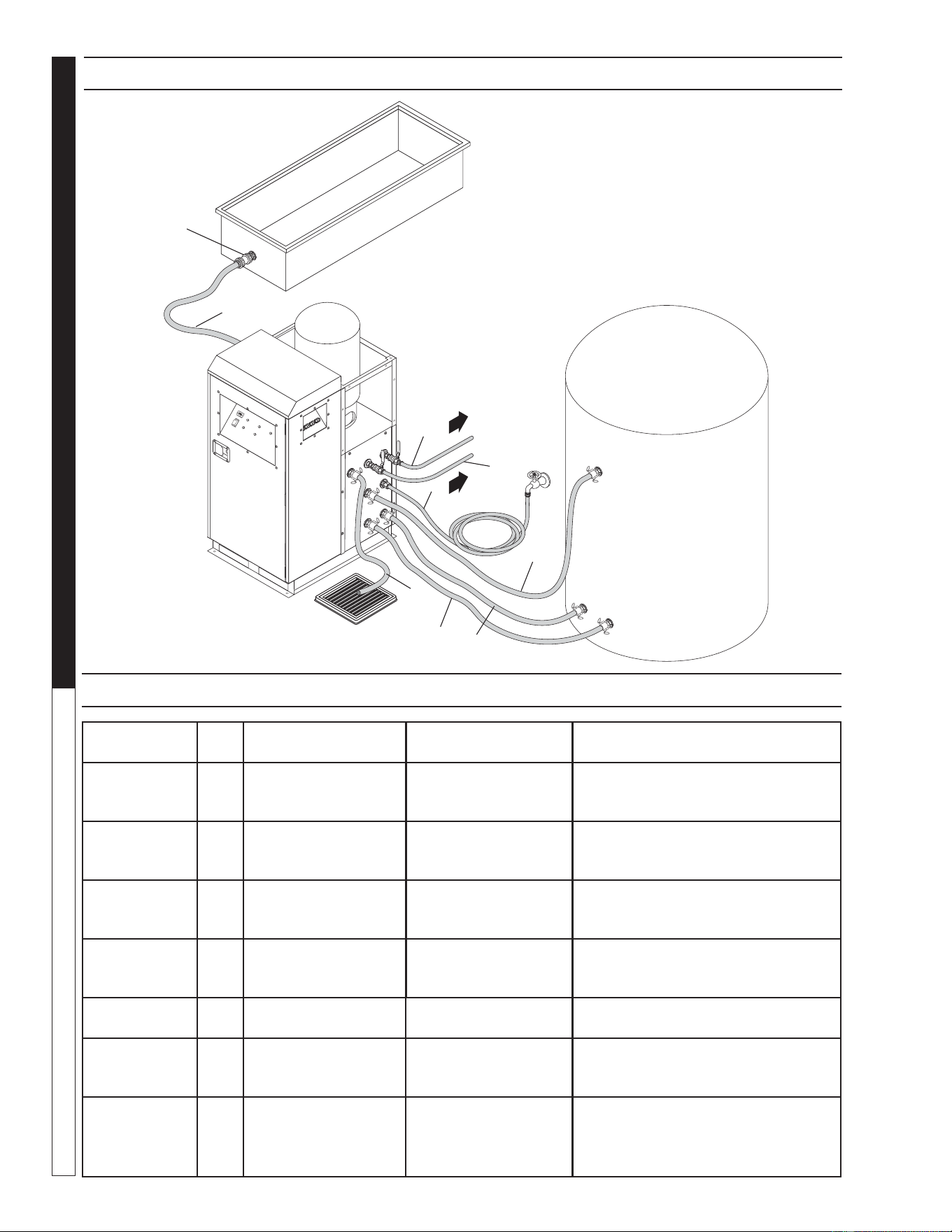
PIPING CONNECTION DIAGRAM
PIPING CONNECTION TABLE
CONNECTION SIZE
EXTERIOR
CONNECTION TYPE DESCRIPTION
INSTALLATION
RECOMMENDATIONS
A1"
CAMLOCK,
1" HOSE BARB
(8.711-811.0)
DRAIN
OUTLET
No valves should be placed
between outlet and drain in case
water overfl ow needs to be purged.
B1, B2 1"
CAMLOCK,
1" HOSE BARB
(8.711-811.0)
INLETS FROM
STORAGE TANK
Valves should be installed inline
for ease of maintenance.
C1"
CAMLOCK,
1" HOSE BARB
(8.711-811.0)
STORAGE
TANK OUTLET
D1"
3/4" GARDEN HOSE,
MALE
FRESH
WATER INLET
Inlet should be directly connected
to fresh water and should always
be left open.
E1"
3/4" GARDEN HOSE,
FEMALE
PRESSURE WASHER
OUTLET
F1"
3/4" GARDEN HOSE,
FEMALE
AUXILIARY
FRESH WATER
OUTLET
Outlet is directly connected to fresh
water inlet and can be used as
normal wall faucet.
G1"
CAMLOCK,
1" HOSE BARB
(8.711-811.0)
INFEED
SOURCE
INLET
Line from infeed /sump tank needs
check valve (provided) installed near
tank outlet, with fl ow directed away
from tank.
S
e
n
D
E
C
T
A
C
H
/H
O
U
R
1
/
1
0
89174360-9
G
A
F
E
D
C
B1
Check
Valve
B2
Water Maze REC2-20 • 8.917-436.0 - E
11
WATER TREATMENT SYSTEM
OPERATOR’S MANUAL
S
e
n
D
EC
T
A
C
H
/
H
O
U
R
1
/
1
0
89174360-10
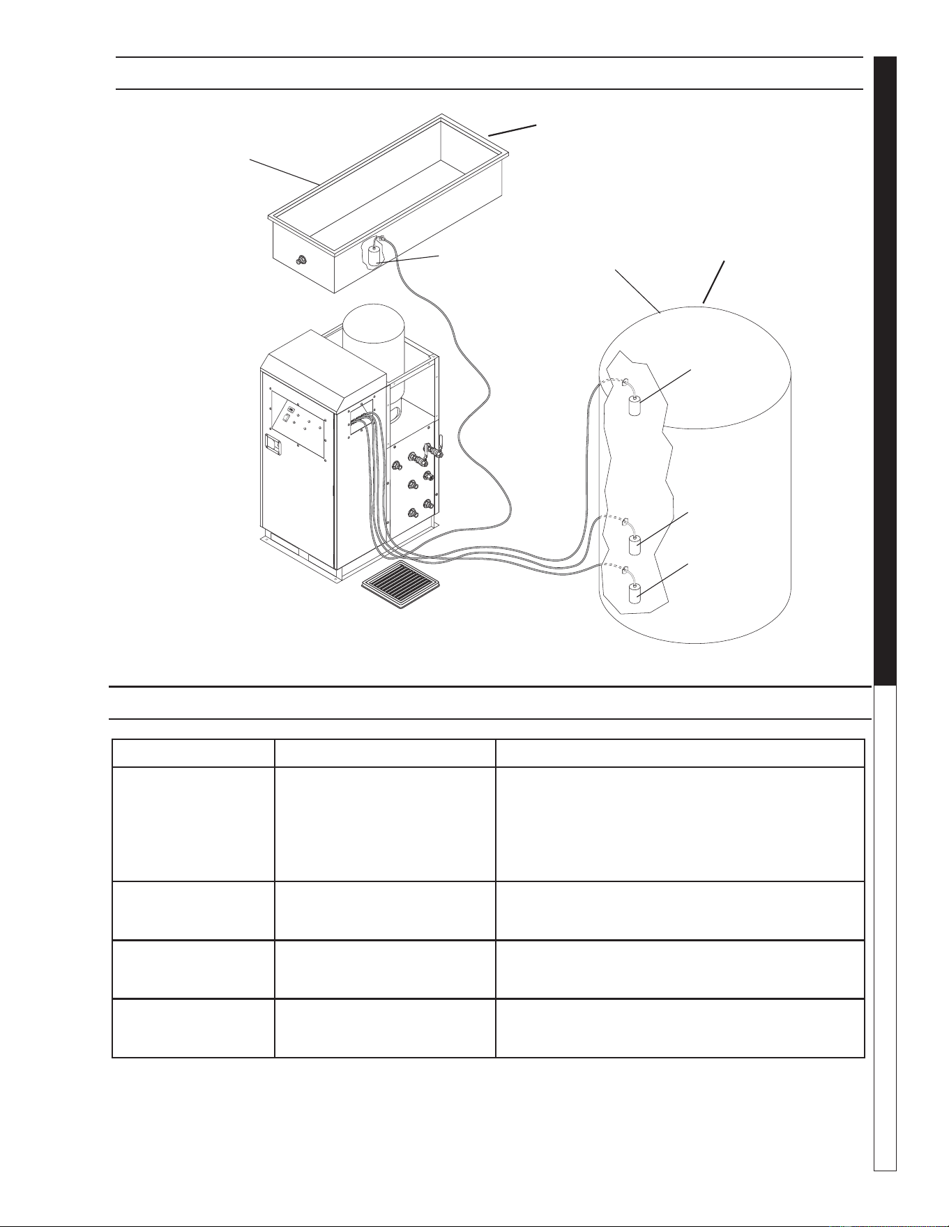
FLOAT CONNECTION DIAGRAM
FLOAT CONNECTION TABLE
FLOAT NAME FLOAT FUNCTION PLACEMENT NOTES
INFEED TANK FLOAT
(NOT PROVIDED)
(WaterMaze #
8.716-143.0)
Signals REC2-20 module
to remove water from
infeed source.
Float needs to close (Lowered position) before
infeed/sump tank water level drops below suction
port to prevent dry running and loss of pump prim-
ing. For convenience, a "Delay Off" function for the
infeed pump is available. To fi ne tune pumps turn off
timing. See digitial timer instructions to set function.
HIGH WATER FLOAT Signals REC2-20 module
to purge excess water from
storage tank.
Float needs to open (raised position) before water
reaches overfl owing levels.
FRESH WATER FILL
LEVEL FLOAT
Sets the water level that
REC2-20 will fi ll to with
fresh water.
Float will maintain a water level of at least its open
or raised position.
LOW WATER FLOAT Shuts off pumps if water level
if too low for protection
against dry running.
Float needs to close (lowered position) before
storage tank level drops below suction ports
to prevent dry running and loss of pump priming.
*All fl oats are to be wired into REC2-20 module junction box, as indicated by junction box label. See included
junction box wiring diagram, page 34, for fl oat placement on terminal block. Junction box terminal block can
be reached by removing four bolts and blue cover plate seen in the exploded view of junction box.
Infeed
Sump Tank
Storage Tank
High Water
Float
(NC)
Fresh Water
Float
(NC)
Low Water
Float
(NC)
Infeed Tank
Float (NC)
Not
Provided
Not
Provided

Water Maze REC2-20 • 8.917-436.0 - E
OPERATOR’S MANUAL WATER TREATMENT SYSTEM
12
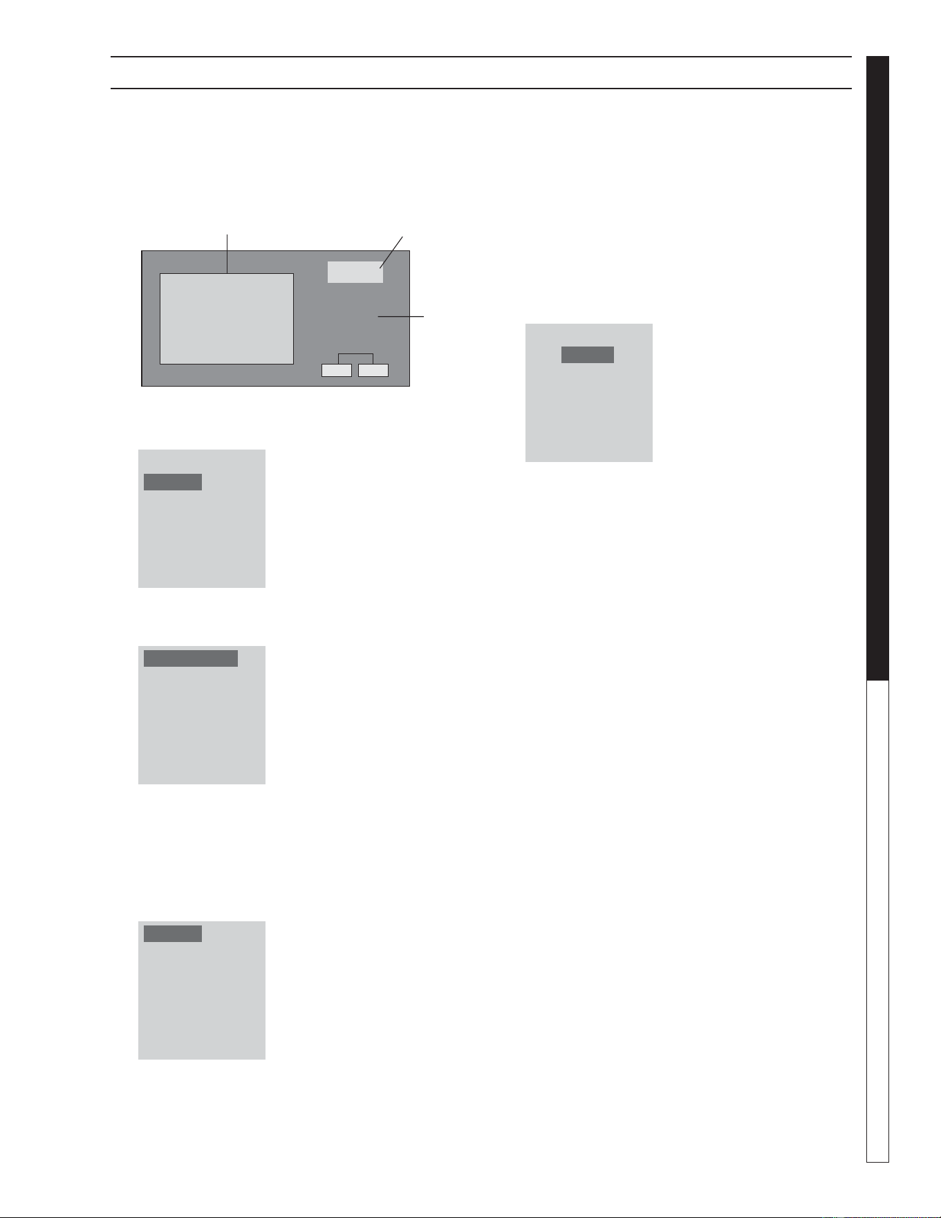
DIGITAL TIMER INSTRUCTIONS
PARAMETER SETTINGS
The following are instructions on how to set the pa-
rameters on the digital timer, located in the electrical
box, in Programming Mode. To defi ne these settings
please follow the steps below.
Setting the Clock:
In order for the system to function properly you must
accurately set the correct time-of-day and date.
1. Press the ESC key located next to the display
window and under the arrow key pad (see fi gure
below). Pressing the ESC key will access the
Parameter Assignment Menu.
2. Using the up/down arrow keys ▲ or ▼, move the
cursor to highlight ‘Setup’ and press OK to accept.
3. Move the cursor to highlight ‘Clock’ and press OK
to accept.
4. Move the cursor to highlight ‘Set Clock’ and press
OK to accept.
Mo 10:15
2006-10-13
ESC OK
Program CardParameter Assignment Menu
Arrow
Key Pad
NOTE: When setting time on clock, use only military
time.
5. Move the cursor to the value wanting to be
changed using the left/right arrow keys or ,
and change the value by using the up/down arrow
keys ▲ or ▼. When you are done setting the time
and date press OK to accept your changes.
6. Press ESC three times to exit to the main menu.
Stop
Program
Setup
Network
Diagnostics
Msg Cong
Start Screen
Clock
LCD
Menu Language
Switch to OP
NTP
Set Clock
S/W Time
Set Clock
Mon. 10:15
YYYY-MM-DD
Water Maze REC2-20 • 8.917-436.0 - E
13
WATER TREATMENT SYSTEM
OPERATOR’S MANUAL
DIGITAL TIMER INSTRUCTIONS
Setting water circulation times and ozone
treatment for machines with option:
1. Press the ESC key located next to the display
window and under the arrow key pad to access
the Parameter Assignment Menu.
2. Using the up/down arrow key ▲ or ▼, move the
cursor to highlight ‘Program’ and press OK to con-
fi r m .
3. Using the up/down arrow key ▲ or ▼, move the
cursor to highlight ‘Set Parameter’ and press OK
to confi rm.
4. The display window will display the Timers. The
display window shows CIRC/OZ, DELAY OFF
AND ON DELAY. CIRC /OZ comes factofy set at
2 and 4, so water will circulate or be treated with
Ozone, between 2 and 4 am Monday thru Friday.
Highlight the Timer desired to change and press
OK.
NOTE: Ta is the accumulator timer and T is the adjust-
able timer (the variable that changes).
5. Highlight the T fi eld and press OK to edit the value.
Use the left/right arrow keys or , move the
cursor to the used the up/down arrow keys ▲ or
▼ to change this value. Each timer has optional
units of time in seconds (s), minutes (m), and hours
(h). To change the unit of time using the arrows up/
down keys ▲ or ▼. Once all values have been set
press, OK to accept and ESC to back up to the
Timer selection menu.
Repeat steps 5 and 6 for the other times if needed.
When fi nished press ESC three times to go to the
main menu.
6. The DELAY OFF function can be used to delay
the shut off of the infeed pump in cases when ad-
ditional water removal is required after the infeed
fl oat is lowered. This function should be used with
caution to prevent the pump from over drawing the
infeed source and dry running. The DELAY OFF
function is factory se at 0 seconds.
7. The ON DELAY function can be used to delay the
start-up of the infeed pump when the upstream
water supply is not being fed quickly enough. This
function should be used with caution so as not to
allow the supply tank to overfi ll before letting the
infeed pump start up. The ON DELAY function is
factory set at 3 seconds.
Mo 10:15
2006-10-13
ESC OK
Program CardParameter Assignment Menu
Arrow
Key Pad
Stop
Program
Setup
Network
Diagnostics
Set Parameter
Prog Name
CIRC/OZ
DELAY OFF
ON DELAY
CIRC/OZ 1/1
D1= MTWTF
ON1= 02:00
OFF1= 04:00
Water Maze REC2-20 • 8.917-436.0 - E
OPERATOR’S MANUAL WATER TREATMENT SYSTEM
14
CENTRIFUGAL PUMP
Your centrifugal pumps have been quality-built and
engineered to give you effi cient, dependable service.
They are equipped with union connectors to make
installation and future service easier.
The advanced design uses a single speed motor which
reduces operation and maintenance to simple, com-
mon-sense procedures.
PUMP OPERATION
(Infeed Transfer and Ozone Pumps)
WARNING
RISK OF ELECTRIC
SHOCK: USE
CAUTION WHEN
HANDLING.
WARNING: Do not touch pumps,
pump motors, water or dis-
charge piping when the pumps
are connected to electrical
power. Do not handle a pump or
pump motor with wet hands or
when standing on a wet or damp
surface or in water. Never touch
a pump or discharge piping
when a unit is operating or fails
to operate. Always disconnect the pump cord
(power) before handling.
1. The shaft seal depends on water for lubrication.
Do not operate the pump unless there is water. Dry
running (pump not pumping water) will cause seal
damage and eventual pump failure.
2. The motor is equipped with an automatic reset
thermal protector. This means if the temperature in
the motor should rise unduly, the switch will cut off
all power before damage can be done to the motor.
When the motor has cooled suffi ciently, the switch
will reset automatically and restart the motor. If the
protector trips repeatedly (cycling on protector)
the pump should be removed and checked for the
cause of the diffi culty. Low voltage, long extension
cords, clogged impeller, very low head or lift, etc.,
could cause cycling. Cycling of the protector will
cause eventual motor burnout.
PUMP MAINTENANCE
WARNING
RISK OF ELECTRIC
SHOCK: USE
CAUTION WHEN
HANDLING.
WARNING: Before attempting to
service, disconnect power from
unit. Do not handle the pump
with wet hands or when stand-
ing on a wet or damp surface or
in water. Failure to follow
precautions can result in per-
sonal injury and /or property
damage.
NOTE: Only qualified electricians or servicemen
should attempt to repair this unit. Improper repair and/
or assembly can cause an electrical shock hazard.
1. Bearings in this unit are pre-lubricated. No ad-
ditional lubrication is necessary.
2. Cleaning - Occasionally clean the transfer pit and
pump if dirt or foreign matter accumulate. Small
stones, gravel, sand, dirt, silt, etc. can clog and dam-
age the pump and pump seal, eventually causing
pump failure.
3. Disassembly of the motor prior to expiration of the
warranty will void the warranty. It may also cause
internal leakage and damage to the unit. If repairs
are required, return the pump to a local service
station.
4. If the motor has been disassembled or the switch
chamber opened after the warranty expiration
date, the O-rings and gaskets must be replaced.
Care must be taken to assure that the seals, the
switch cover and air tube gaskets do not leak.
5. The pump should be checked for proper opera-
tion weekly or monthly by watching the operation
of the pump. If anything has changed since the
pump was new, the pump should be examined,
and repaired if necessary.
OPERATION AND MAINTENANCE

Water Maze REC2-20 • 8.917-436.0 - E
15
WATER TREATMENT SYSTEM
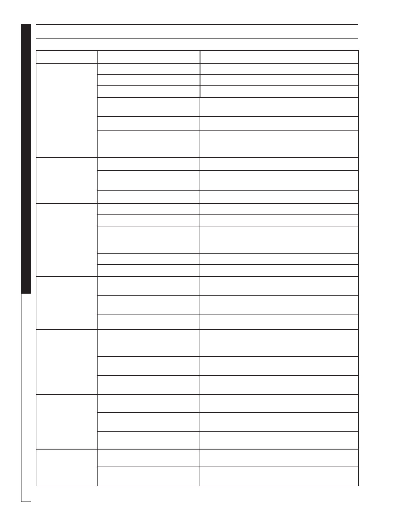
Troubleshooting Guide
PROBLEM POSSIBLE CAUSE SOLUTION
INFEED PUMP
DOES NOT
OPERATE
Sump or pre-treatment tank has low
water level
Raise level in sump or pre-treatment
tank.
Control panel pump switch is in the
OFF position
Confi rm that control panel pump switch is
in the ON position.
TRANSFER
PUMP
DOES NOT
OPERATE
Storage has low water level Ensure tank is fi lling with fresh water and
wait.
Pressure limit has been achieved Need water demand for pump to start.
Control panel pump switch is in the
OFF position
Confi rm that control panel pump switch is
in the ON position.
PUMP
DOES NOT
OPERATE
Program timer is not set for current
time
See Digital Timer Instructions
page to reset circulation times.
Storage tank has low water level Ensure tank is fi lling with fresh water and
wait.
TROUBLESHOOTING - PUMP
Water Maze REC2-20 • 8.917-436.0 - E
WATER TREATMENT SYSTEM
Troubleshooting Guide
16
TROUBLESHOOTING - PUMP
PROBLEM POSSIBLE CAUSE SOLUTION
ONE OF THE
PUMPS DOES
NOT TURN ON
Circuit breaker shut "OFF Turn "ON" circuit breaker.
Accumulation of trash on fl oat Clean fl oat.
Float obstruction/defective fl oat Check fl oat path and provide clearance.
Defective switch Have pump serviced by authorized service center.
Defective motor Have pump serviced by authorized service center.
Low line voltage If voltage under recommended minimum, check
size of wiring from main switch on property.
If OK, contact power company.
ONE OF THE
PUMPS WILL
NOT SHUT OFF
Float obstruction Check fl oat and fl oat rod path. Provide clearance.
Pump is air locked (Infeed
pump)
Shut power off for approximately 1 minute, then
restart. Repeat several times to clear air from pump.
Defective fl oat switch Disconnect switch, check with ohmmeter.
ONE OF THE
PUMPS RUNS
BUT DOES NOT
DISCHARGE
LIQUID
Lift too high for pump Check rating table. See pages 32 and 33.
Inlet to impeller plugged Pull pump and clean.
Low line voltage If voltage under recommended minimum, check
size of wiring from main switch on property.
If OK, contact power company.
Clogged impeller Remove housing, unclog.
Faulty motor protector Replace pump.
ONE OF THE
PUMPS DOES
NOT DELIVER
RATED
CAPACITY
Low voltage, speed too slow Check for proper supply voltage to make
certain it corresponds to nameplate voltage.
Impeller or discharge pipe is
clogged
Pull pump and clean. Check pipe for scale or
corrosion.
Impeller wear due to abrasives Replace worn impeller.
ONE OF
THE PUMPS
CYCLES
CONTINUALLY
Low line voltage If voltage under recommended minimum, check
size of wiring from main switch on property.
If OK, contact power company.
Worn or defective pump parts
or plugged impeller
Replace worn parts or entire pump.
Clean parts if required.
Pump air locked Turn pump "ON" and "OFF" several times.
Fill hose manually with water.
TRANSFER
PUMP
DOES NOT
STARTUP
Lack of water in tank Add water
Bad low water protection fl oat
in tank
Replace fl oat
Pump switch off Turn on main switch
TRANSFER
PUMP
DOES NOT
SHUT OFF
Surge tank pressure too high Lower air pressure to 18 psi
Pressure switch cut off, setting
too high
Lower cut off pressure to 40 psi
Adjust small spring - rotate counterclockwise

Water Maze REC2-20 • 8.917-436.0 - E
17
WATER TREATMENT SYSTEM
Troubleshooting Guide
TROUBLESHOOTING - PUMP MOTOR
PROBLEM POSSIBLE CAUSE SOLUTION
MOTOR WILL
NOT RUN
Disconnect switch is "OFF" Be sure switch is on.
Breaker is tripped Reset breaker.
Starting switch is defective Replace starting switch.
Wires at motor are loose,
disconnected or wired incorrectly
Refer to wiring instructions.
Check and tighten all wiring.
MOTOR RUNS HOT
AND OVERLOAD
KICKS OFF
Motor is wired incorrectly Refer to wiring instructions
Voltage
is too low
Check with power company. Install heavier
wiring if wire size is too small. See wiring
instructions.
Defective fl oat switch Disconnect switch, check with ohmmeter.
MOTOR RUNS BUT
NO WATER IS
DELIVERED
Pump in a new installation did
not pick up prime through:
a. Improper priming a. Re-prime (3 or 4 times may be needed)
by stopping and starting motor several
times.
b. Air leaks b. Check all connections on suction line.
Pump has lost its prime through:
a. Air leaks a. Check all connections on suction line, air
volume control, jet and shaft seal.
b. Water level below suction of
pump
b. Lower suction line into water and
re-prime.
Check valve is stuck in closed
position
Replace check valve.
Pipes are frozen Thaw pipes. Bury pipes below the frost line.
Heat pipes below frost line. Heat pit or pump
house.
Water Maze REC2-20 • 8.917-436.0 - E
WATER TREATMENT SYSTEM
Troubleshooting Guide
18
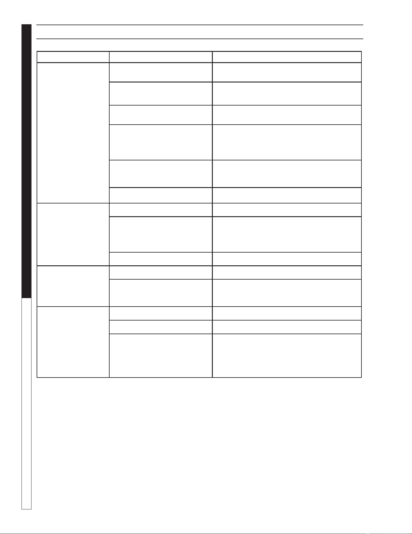
PROBLEM POSSIBLE CAUSE SOLUTION
VALVE LEAKS
WHEN "OFF"
Dirt or debris on diaphragm
seat
Clean diaphragm seat.
Solenoid not fully closed after
manual operation
Turn solenoid clockwise to fully seated
position.
Solenoid O-ring damaged or
twisted
Turn off water, inspect O-ring.
Reseat if twisted, replace solenoid value.
Diaphragm damaged Turn off water, remove bonnet screws and
inspect diaphragm for nicks or damage
NOTE: Diaphragm has one bleed hole
molded into it. Replace solenoid valve.
Dirt interfering with solenoid
operation
Turn off water, remove solenoid and fl ush
seating surface in bonnet and at bottom of
solenoid with water.
Solenoid damaged Turn off water supply and replace solenoid.
WATER WON'T
SHUT OFF
Valve in manual "ON" position Turn solenoid clockwise to "OFF" position.
Diaphragm bleed hole blocked Use Manual Flush Mode. Turn water supply
"OFF" and immediately back "ON" to clear
blockage. If still blocked, turn off water and
inspect diaphragm looking for blockage.
Damaged solenoid Turn off water supply and replace solenoid.
LOW OR
INADEQUATE
FLOW
CONDITION
Gate valve not fully open Open gate valve fully.
Pipeline blockage Clear pipeline.
VALVE WON'T
TURN ON
ELECTRICALLY
No power to solenoid Check fl oats in tank
Low voltage Check for proper voltage to unit.
No water pressure Make sure water pressure is available to valve.
Turn off water, without cutting wires, unscrew
and swap solenoids between valves. Turn on
water and test again. If problem stems from
the solenoid, replace solenoid.
TROUBLESHOOTING - WATER SOLENOID
Water Maze REC2-20 • 8.917-436.0 - E
19
WATER TREATMENT SYSTEM
Troubleshooting Guide
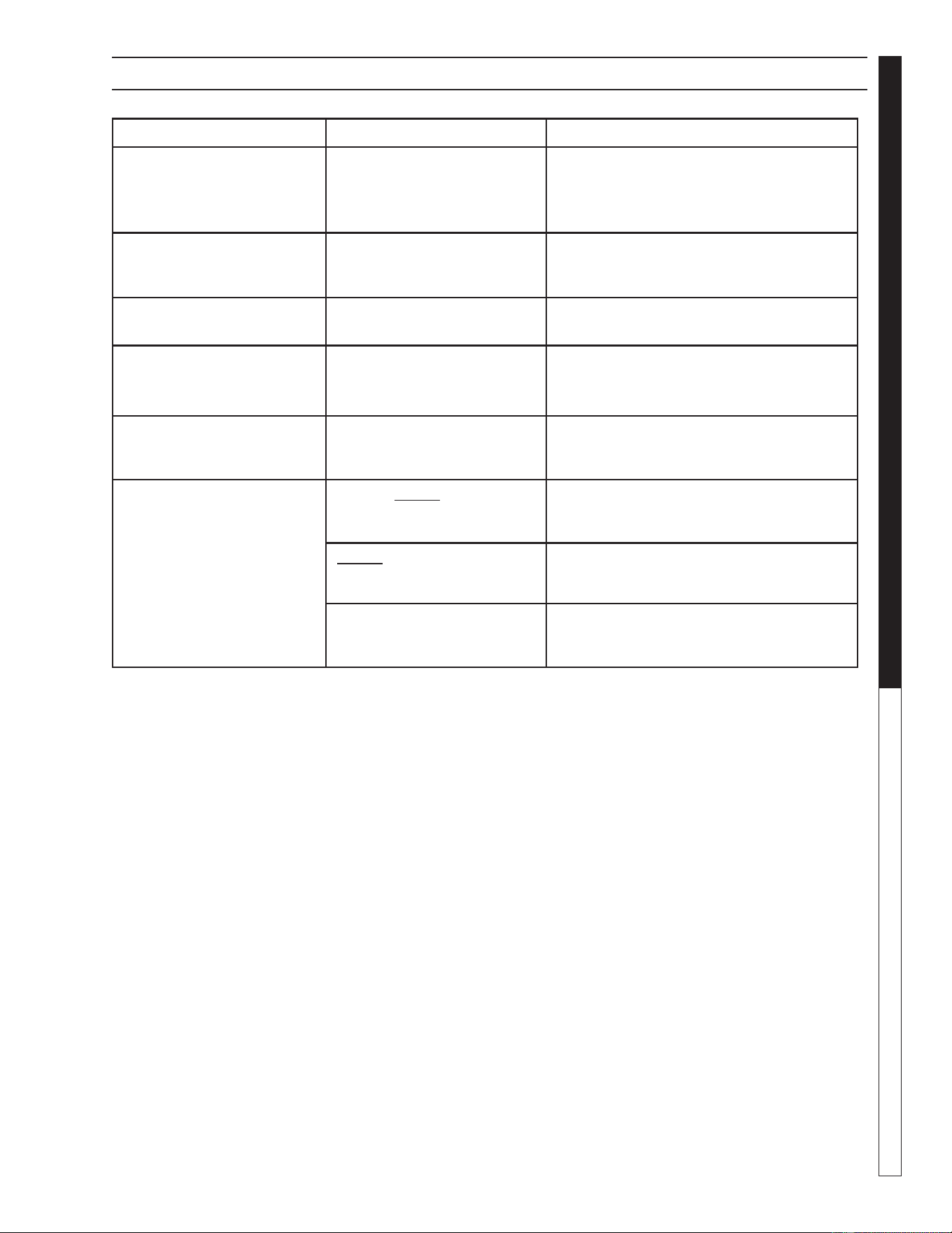
PROBLEM POSSIBLE CAUSE SOLUTION
CRACKED
OR BROKEN
STATIONARY SEAT
(CERAMIC)
Seal ran dry and heated up.
When liquid reached seal
faces it was cooler, causing
thermal cracks
Check to insure seal chamber is full of
liquid before starting pump. On high
temperature application insure proper
fl ushing at seal faces.
CARBON WASHER
SCORED AND GROOVED
Dirty system Have system cleaned and fl ushed.
Consider use of Tungsten Carbide
or Silicon Carbide Rings.
CARBON WASHER
WORN UNEVENLY
Seal improperly installed Check installation instructions
for proper assembly.
BUNA DIAPHRAGM
HARD OR BRITTLE.
RAPID CARBON WEAR.
Air leak on suction side of
pump
Check cover gasket, hand knobs, hose,
clamps, etc. Replace or tighten as
necessary.
DIAPHRAGM SOFT
AND STICKY; APPEARS
TO BE DISSOLVING.
Bellows not compatible
with material being pumped
Consult dealer for recommendation
advising of pumpage and temperature.
"OPTIONAL"
OZONE GENERATOR
DOES NOT TURN ON
DURING PROGRAMMED
CIRCULATION TIME
(INDICATED BY GREEN
LIGHTS ON OZONE BOX
INSIDE REC2-20
CABINET)
Time or Ozone program
is not set correctly
Consult manual for proper setting on add-
ing additional ozone/recirculation time.
Ozone generator power
switch is not on
Turn on ozone power switch on cabinet.
Green lights on ozone
generator start off green
then go dim, bright
Proper operation-If lights stay bright
green, then problem with ozone bulb
or ballast - refer to manual.
TROUBLESHOOTING - WATER SEALS
Water Maze REC2-20 • 8.917-436.0 - E
OPERATOR’S MANUAL WATER TREATMENT SYSTEM
20
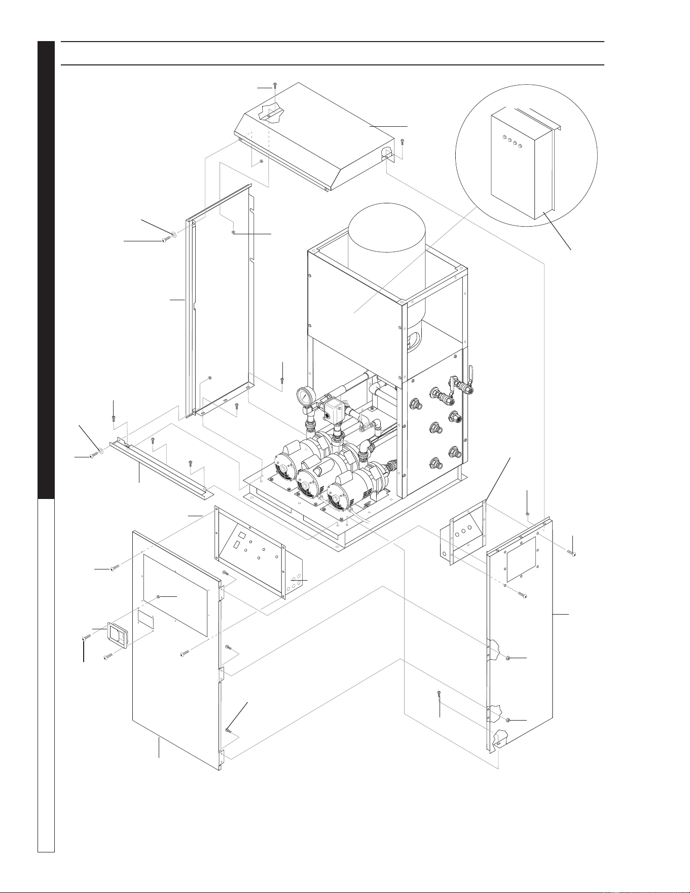
89174360-7
9
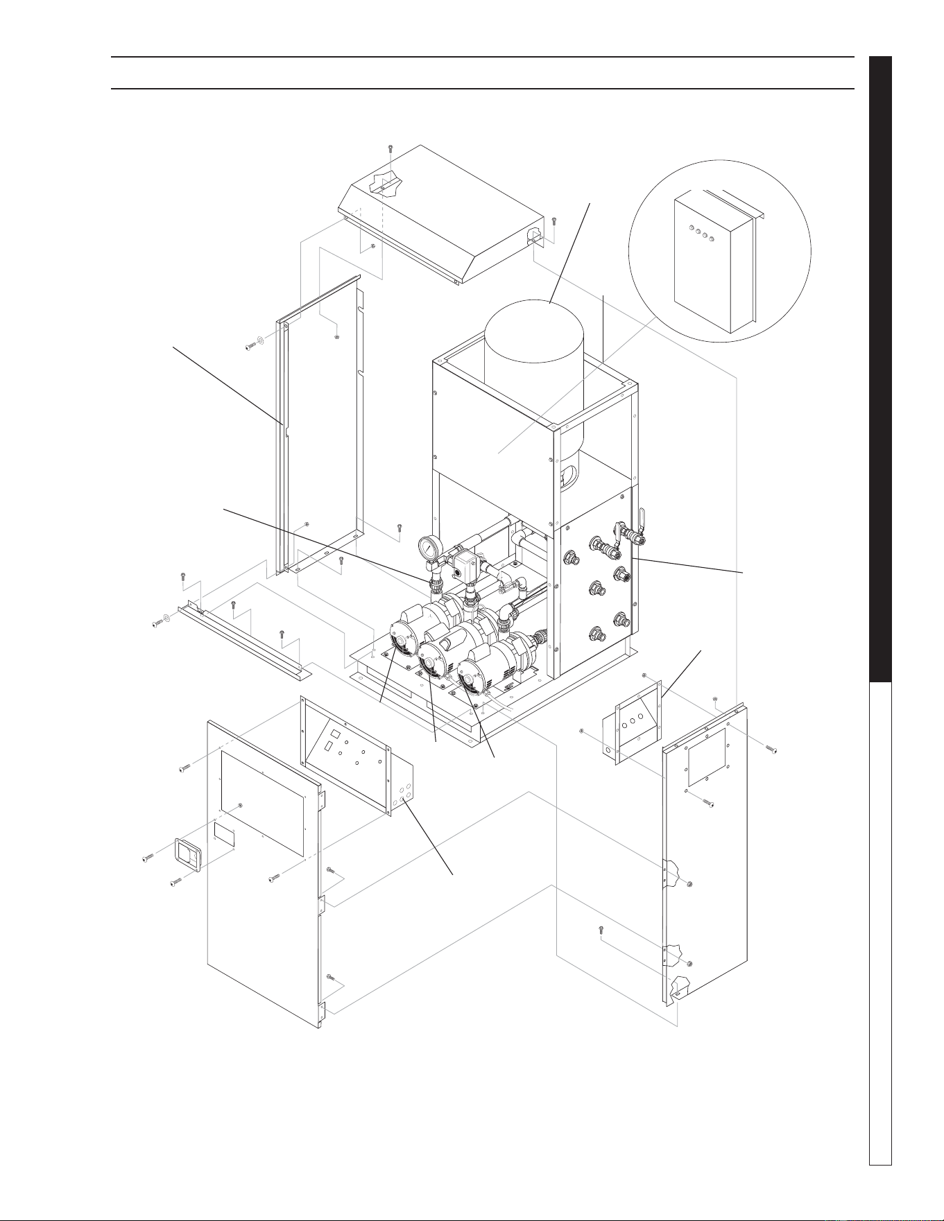
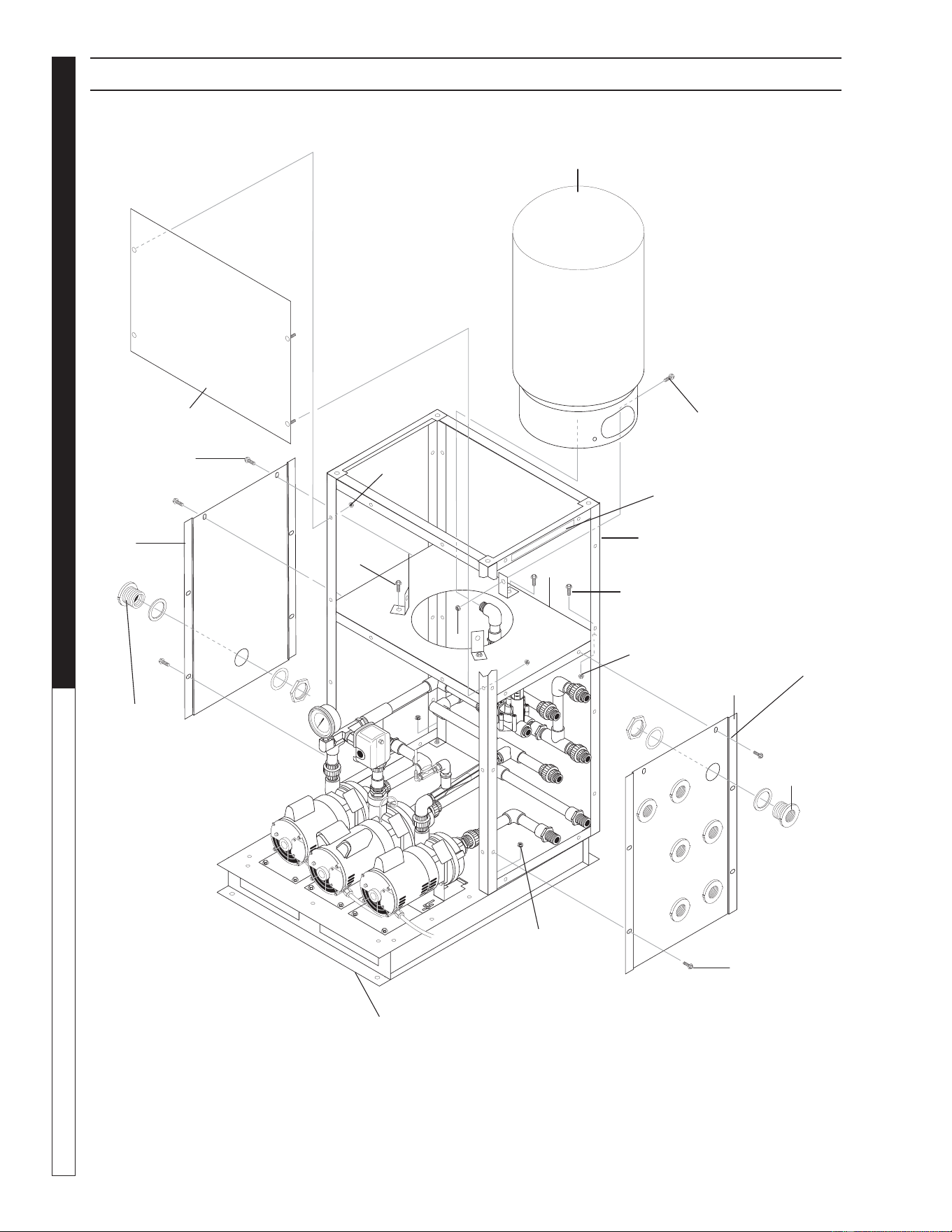
EXPLODED VIEW – BODY
3
10
8
9
11
6
13
10
1
2
4
9
5
7
9
13
10
12
14
See Right
Side Panel
page 28 for
connections

Water Maze REC2-20 • 8.917-436.0 - E
21
WATER TREATMENT SYSTEM
OPERATOR’S MANUAL
ITEM PART NO. DESCRIPTION QTY
1 8.917-450.0 WLMT, Base Recycle 1
2 8.917-452.0 WLMT, Panel, Back, Recycle 1
3 8.917-457.0 WLMT, Tank Stand Frame,
Recycle 1
4 8.917-435.0 WLMT, Top, Tank Stand,
Recycle 1
5 8.917-438.0 Panel, Left, Tank Stand,
Recycle 1
6 8.917-444.0 Panel, Right, Tank Stand,
Recycle 1
7 8.917-449.0 Bracket, Tank Base, Recycle 3
8 8.719-178.0 Tank, 20 Gal Prepressurizd,
Blue, WTRSTX-202 1
9 9.803-277.0 Screw, 5/16" x 1/2", Whiz Loc
Flange 19
ITEM PART NO. DESCRIPTION QTY
10 9.802-778.0 Nut, 5/16" Whiz Loc
Flange 8
11 9.802-754.0 Screw, 1/4" x 1/2" NC, Whiz Loc
Flange 3
12 9.802-775.0 Nut, 1/4" Flange, ZN 3
13 8.706-484.0 Bulkhead, 1" Polypro 8
14 9.800-348.0 Label, Do not stand on Frame 2
15 9.800-016.0
Label, Disconnect
Power supply 1
16 9.800-347.0
Label, Warnings 1
EXPLODED VIEW PARTS LIST– BODY
Not Shown
Water Maze REC2-20 • 8.917-436.0 - E
OPERATOR’S MANUAL WATER TREATMENT SYSTEM
22
89174360-12
13
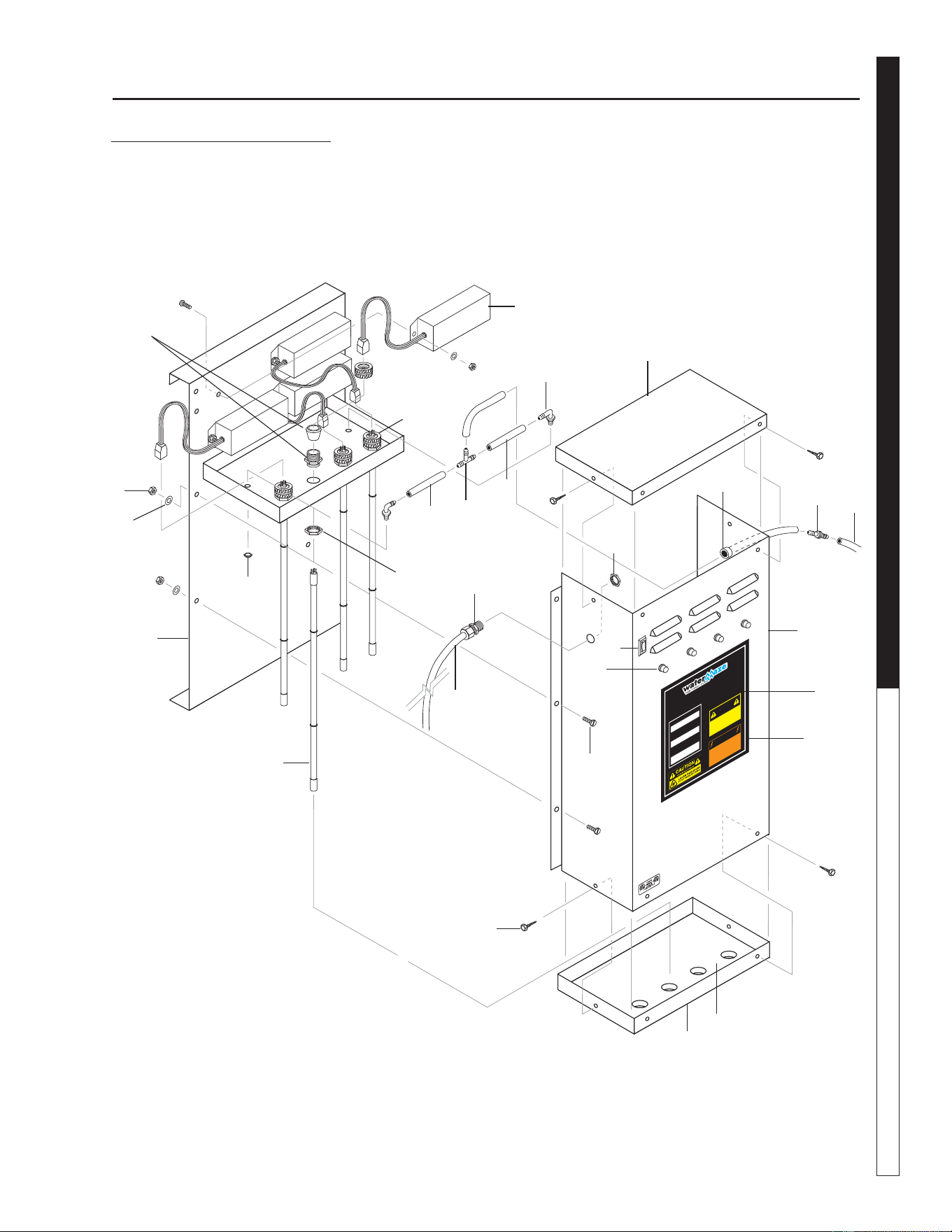
CABINET EXPLODED VIEW
9
11
13
5
3
2
4
9
10
1
15
3
13
7
14
11
10
11
12
8
9
6
13
11
12
Ozone
Generator
(Option)
16

Water Maze REC2-20 • 8.917-436.0 - E
23
WATER TREATMENT SYSTEM
OPERATOR’S MANUAL
CABINET EXPLODED VIEW PARTS LIST
ITEM PART NO. DESCRIPTION QTY
1 8.917-456.0 Wlmt, Door, Recycle 1
2 8.917-536.0 Wlmt, Junction Box, Recycle 1
3 8.917-431.0 Panel, Right Side, Cabinet,
Recycle 1
4 8.917-432.0 Panel, Left, Cabinet, Recycle 1
5 8.917-428.0 Top, Cabinet, Recycle 1
6 8.917-430.0 Base, Cabinet, Recycle 1
7 8.719-087.0 Latch, Paddle Handle w/Key 1
8 8.917-455.0 Wlmt, Control Panel, Rec2-20 1
9 9.803-277.0 Screw, 5/16" x 1/2",
Whiz Loc Flange 9
10 9.802-754.0 Screw, 1/4" x 1/2" NC,
Whiz Loc Flange 12
11 9.802-775.0 Nut, 1/4" Flange, ZN 12
12 8.718-980.0
Washer, 5/16", Flat, SAE
4
13 9.803-541.0 Screw, 5/16-18 x 1/2 CS
SOC BH NC ZN 20
14 8.718-753.0 Screw, 1/4"-20 x 3/4" PHIL
PH SS M/S 4
15 8.718-882.0 Nut, 1/4-20 NC KEPS SS 4
16 8.905-717.0 Ozone Generator, Series 400
(Option only) 1
Water Maze REC2-20 • 8.917-436.0 - E
OPERATOR’S MANUAL WATER TREATMENT SYSTEM
24
89174360
-
GROU
ND
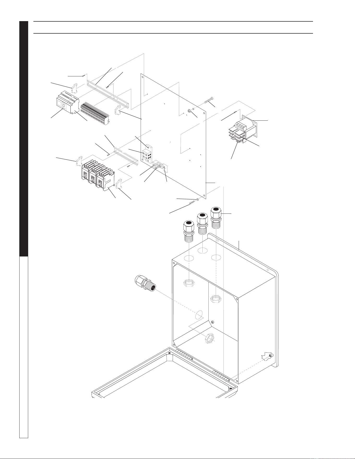
EXPLODED VIEW ELECTRICAL BOX
19
17
1
2
4
14
20
18
13
12
11
9
8
15
3
6
5
10
7
7
6
11
11
17
11
4
17
17

Water Maze REC2-20 • 8.917-436.0 - E
25
WATER TREATMENT SYSTEM
OPERATOR’S MANUAL
ELECTRICAL BOX EXPLODED VIEW PARTS LIST
ITEM PART NO. DESCRIPTION QTY
1 8.716-180.0 Fuse, KTK-R4 600V
Midget Fuse (4 AMP) 2
2 8.716-883.0 Transformer, 208/230/460V-
24/115V, .050 KVA 1
3 8.716-460.0 Terminal, Grounding Lug,
LAMA6-14Q 1
4 9.802-457.0 DIN Rail, 35 MM Cut to Fit
5 9.800-040.0 Label, Ground Symbol 2
6 9.802-762.0 Screw, 10/32" x 1-1/4"
RH, SL, BLK 2
7 9.802-695.0 Nut, 10/32" Keps 12
8 8.714-164.0 Terminal Block- 2 Position
(Surface) BL-BL 1
9 8.718-937.0 Screw, #8 x 3/4", Phillips, Zinc
PLTD, HEX, T 2
10 9.802-759.0 Screw, 10/32" x 1/2"
BHSOC BLK 5
11 8.718-936.0 Screw, #8 x 1/2"" Phillips, Zinc
PLAT TEK 9
12 8.756-361.0 Relay, Smart, 24V, 8I/4O, FS 1
13 8.755-623.0 Logo Expansion Module 4I/4O 1
14 8.716-199.0 Fuse, FNM-6.25 1
15 8.724-267.0 Contractor, DP C25DNY151TL,
15 AMP 3
16 8.749-976.0 Terminal Block, Feed- through,
Phoenix 25
17 9.804-595.0 End Bracket, Entrelec,
103-002-26 4
18 8.716-281.0 Box, Plastic, 14" x 16" x 6.75"
W/Hinged Lid 1
19 9.802-518.0 Strain Relief, LT, STR, 3/4
NPT .49-.71D 4
20 8.917-612.0 Electrical Standoff, Recycle 1
21 8.921-217.0
I BAR, PLC
with two expansions 2
22 8.712-861.0
Edge Trim 0.66'
23 8.921-222.0
Q BAR, Dual expansion Top 1
24 8.921-221.0
Q BAR, PLC with two
expansions 1
25 9.807-874.0
PLC Logic, REC2-20, FS 1
Not Shown
Water Maze REC2-20 • 8.917-436.0 - E
OPERATOR’S MANUAL WATER TREATMENT SYSTEM
26
89174360-2
INFEED
PUMP
RUN TIME
ON
I
OFF
O
8
.
9
1
7
-
6
20
.
0
b
y
TRA
NSFER
PUMP
STORAGE
T
A
NK FULL
STO
RA
GE
TA
NK EMPTY
CIRCULA
TIO
N
PUM
P
FRESH
WATER
F
I
L
L
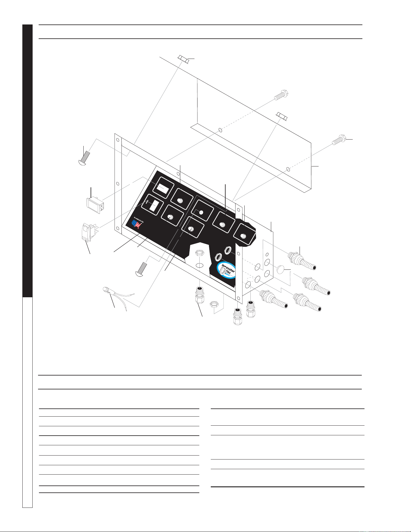
CONTROL PANEL EXPLODED VIEW
4
1
10
8
3
11
6
7
5
CONTROL PANEL EXPLODED VIEW PARTS LIST
ITEM PART NO. DESCRIPTION QTY
1 8.917-455.0 Wlmt, Control Panel, Rec2-20 1
2 8.706-745.0 Plug, Plastic 0.812 1
3 9.802-518.0 Strain Relief 3/4" 3
4 8.716-547.0 Strain Relief 1/2", Conduit 4
5 9.803-651.0 Lamp Indicator, Red 28V 2
6 9.803-650.0 Lamp Indicator, Blue 28V 4
7 8.716-037.0 Switch, Rocker 24V 1
8 9.802-283.0 Hour Meter 1
9 8.917-445.0 Cover, Control, Rec2-20 1
ITEM PART NO. DESCRIPTION QTY
10 9.803-277.0 Screw, 5/16" x 1/2",
Whiz Loc Flange 6
11 9.802-778.0 Nut, 5/16" Whiz Loc Flange 4
12 9.802-514.0 Strain Relief 1/2" (Only On
Machines With Ozone
Generator, In Place Of Plug) 1
13 8.917-620.0 Label, Recycle Control Panel 1
14 8.917-621.0
Label, Recycle
Descriptive Label 1
Not Shown
10
2
13
9
6
5
6
6
Water Maze REC2-20 • 8.917-436.0 - E
27
WATER TREATMENT SYSTEM
OPERATOR’S MANUAL
89174360-4
1
4
3
7
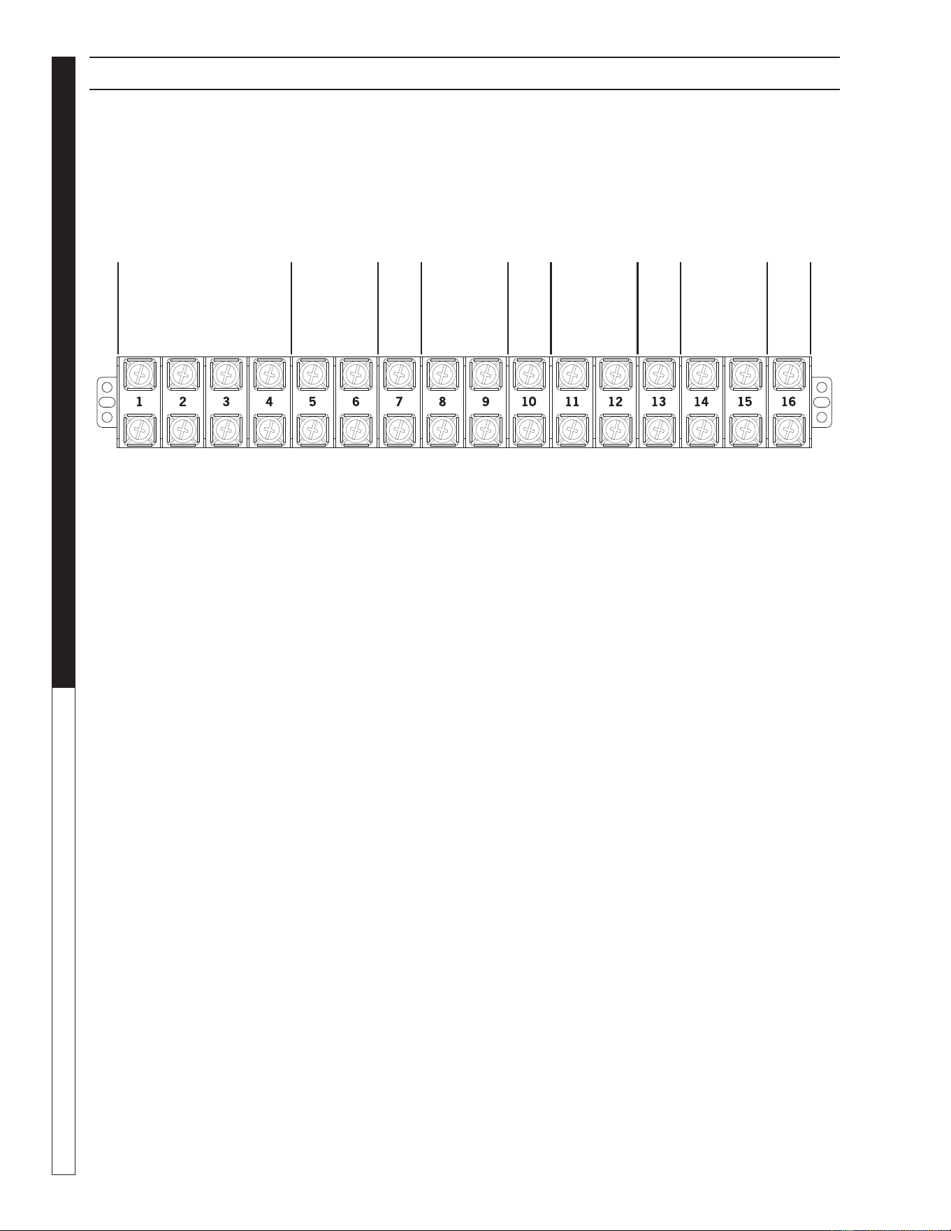
JUNCTION BOX EXPLODED VIEW
JUNCTION BOX EXPLODED VIEW PARTS LIST
ITEM PART NO. DESCRIPTION QTY
1 8.917-536.0 Wlmt, Junction Box, Recycle 1
2 8.917-540.0 Cover, Junction Box, Recycle 1
3 8.716-547.0 Connector, 1/2" L/T, Straight,
Black 2
4 9.802-514.0 Strain Relief, L/T, Str, 1/2 NPT,
.23-.45D 6
5 9.802-749.0 Screw, 8/32" x 3/4" BHSOC 2
6 9.802-785.0 Nut, 8/32" KEPS 2
7 9.802-493.0 Block, Terminal, 16 Pole 1
2
10
11
9
8
ITEM PART NO. DESCRIPTION QTY
8 9.802-759.0 Screw, 10/32" x 1/2"
BHSOC BLK 1
9 9.802-695.0 Nut, 10/32" KEPS 2
10 9.803-277.0 Screw, 5/6" x 1/2", Whiz Loc
Flange 4
11 9.802-778.0 Nut, 5/16" Whiz Loc Flange 4
12 8.917-622.0
Label, Recycle Junction Box 1
6
4
5
Not Shown
Water Maze REC2-20 • 8.917-436.0 - E
OPERATOR’S MANUAL WATER TREATMENT SYSTEM
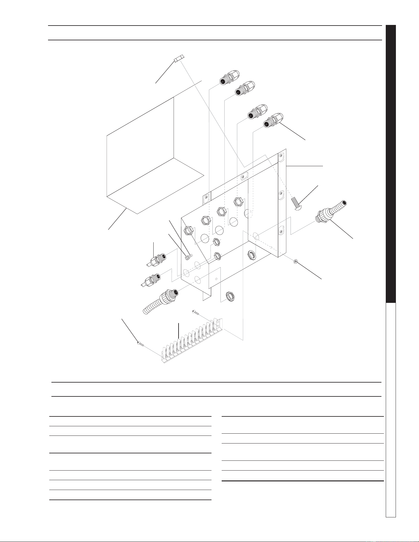
28
89174360-5
DRAIN
OUTLET
PRESSURE
W
ASHER
OUTLET
AUXILIAR
Y FRESH
WA
TER OUTLET
8.917-624.0
STORAGE
T
ANK
OUTLET
FRESH
WA
TER
INLET
8.917-625.0
INLETS FROM STORAGE
TAN K
8.917-626.0
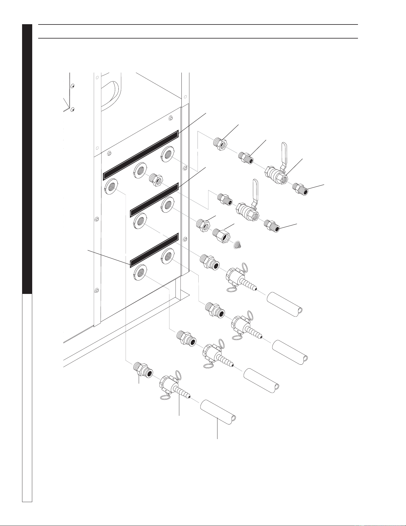
RIGHT SIDE WATER CONTROL PANEL EXPLODED VIEW
1
6
2
4
5
12
12
3
4
7
8
9
10

Water Maze REC2-20 • 8.917-436.0 - E
29
WATER TREATMENT SYSTEM
OPERATOR’S MANUAL
RIGHT SIDE PANEL EXPLODED VIEW PARTS LIST
ITEM PART NO. DESCRIPTION QTY
1 8.706-707.0 Adapter, 1" Male x 1" Male Thrd.
Camlock 5
2 8.706-709.0 Coupler, 1" FEM x 1" Hose Barb
Camlock 5
3 9.802-146.0 Swivel, 1/2" MP x 3/4" GHF
w/Strainer 1
4 8.706-926.0 Bushing, 1" x 1/2" Pipe, Brass 3
5 8.706-790.0 Nipple, 1/2" Close 2
6 8.707.211.0 Valve, 1/2" 8201 Brass Ball 2
400 PSI
7 8.711-811.0 Hose, 1" Gray Spiralite, per foot
Not Provided
8 8.917-624.0 Label, Recycle Outlet To Drain 1
9 8.917-625.0 Label, Recycle Outlet To
Storage 1
10 8.917-626.0 Label, Recycle Inlets
From Storage 1
11 8.917-627.0
Label, Recycle
Infeed Source Inlet 1
12 8.706-968.0 Nipple, 1/2" x 3/4" GH 2
Not Shown
Water Maze REC2-20 • 8.917-436.0 - E
OPERATOR’S MANUAL WATER TREATMENT SYSTEM
30
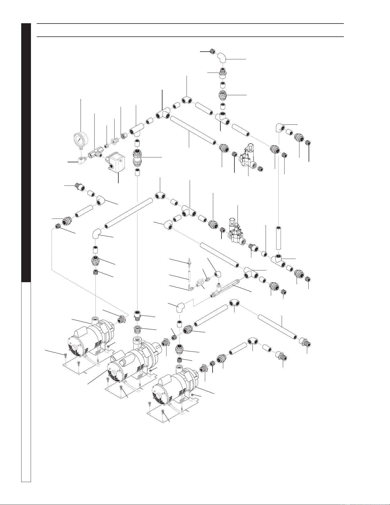
PLUMBING EXPLODED VIEW
89174360-6
10
2
20
14
3
19
12
3
12
12
15
9
18
16
1
6
9
11
14
17
13
23
22
28
24
5
11
14
7
14
9
5
7
17
21
27
25
8
9
4
11
17
26
29
30
29
Infeed
Transfer
Circulation
11
14
14
11
11
11
7
12
7
7
14
7
7
14
11
5
32
33
31
32
31
32
31
33
33
14
11
7
11
9
14
11
14
11
9
12

Water Maze REC2-20 • 8.917-436.0 - E
31
WATER TREATMENT SYSTEM
OPERATOR’S MANUAL
PLUMBING PARTS LIST
ITEM
PART NO. DESCRIPTION QTY
1 8.716-154.0 Switch, Pres SQ D, N/C
Use W/2-10893, 2-1072 1
2 8.712-154.0 Gauge, Pressure 0-100 1/4"
Bottom PG1- 1
3 8.716-697.0 Solenoid, Water Maze,
PVC 24V P/N 100DVF 2
4 8.706-404.0 Bushing, 1 1/2" x 1" MT x FT,
PVC 80 1
5 8.706-405.0 Bushing, 1 1/4" x 1" MT x FT,
PVC 80 3
6 8.706-376.0 Elbow, 1" FIPT x FIPT, PVC 80 1
7 8.706-373.0 Elbow, 1" S x S, PVC 80, 90° 8
8 8.706-378.0 Elbow, 1" SLIP x FIPT,
PVC 80, 90° 1
9 8.706-409.0 Adapter, 1" MT x SLIP, PVC 80 6
10 8.706-447.0 Adapter, 1" , 3/4" S x FIPT,
PVC 80 1
11 8.706-439.0 Nipple, 1", PVC, Close 13
12 8.706-430.0 Tee, 1" S x S, PVC 80 5
13 8.706-432.0 Tee, 1" FT x SLIP x SLIP,
PVC 80 1
14 8.706-471.0 Union, 1" SLIP x FMLE
THRED, PVC 80 SPEA 11
15 8.706-597.0 Union, 1" S x S,
PVC 80 "SPEARS" 1
16 8.707-300.0 Valve, 1" PVC Ball Check 1
17 8.706-366.0 Pipe, 1", PVC 80, /FT Cut to fi t
18 8.706-827.0 Elbow, 1/4" Street 1
19 8.706-854.0 Tee, 1/4" Branch Male 1
20 8.706-777.0 Nipple, 1/4", Close 1
21 8.706-923.0 Bushing, 3/4" x 1/4" Pipe 1
22 8.709-431.0 Injector 1
23 8.706-370.0 Elbow, 1/2" FIPT x FIPT 1
24 8.706-587.0 Nipple, 1/2" x 1/2" 1
25 8.707-321.0 Valve, 1/4" 1
26 8.706-588.0 Connector, 3/8" x 1/4"
Male Elbow 1
27 8.707-355.0 Check Valve 1
28 8.711-733.0 Tubing, 3/8" Vinyl 3 in
29 8.755-986.0 PUMP, SCOT 11, 3/4HP 230V
1PH 4.88DIA 2
30 8.756-757.0 PUMP, SCOT 208/230V 1PH,
20GPM/50PSI 1
31 8.917-454.0 WLMT, Pump Base 3
32 9.802-277.0 Screw, 5/16" x 1/2"
Whiz Loc Flange 6
33 9.802-778.0 Nut, 5/16" Whiz Loc Flange 6
Water Maze REC2-20 • 8.917-436.0 - E
OPERATOR’S MANUAL WATER TREATMENT SYSTEM
32
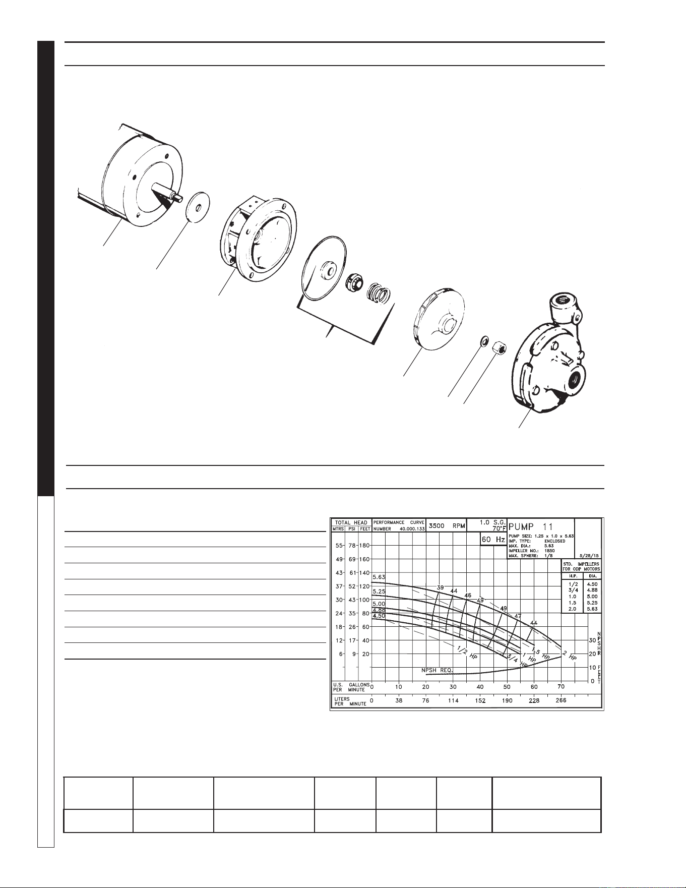
INFEED & CIRCULATION PUMP EXPLODED VIEW
#8.755-986.0 3/4 HP 1PH
ITEM PART NO. DESCRIPTION QTY
1 104.000.171 Flinger 1
2 132.000.337X Adapter 1
3 101.000.239 Seal VN-SIL/SIL 1
4 131.000.763D 4.88" Impeller 1
5 104.000.168 Washer 1
6 105.000.465 Nut 1
7 137.002.664X Case 1
8 Motor, 3/4 HP 230V 1 PH 1
1
2
3
4
5
6
7
8
INFEED & CIRCULATION PUMP EXPLODED VIEW PARTS LIST
BRAND MODEL NO.
SIZE
INLET OUTLET AMPS VOLTS PHASE MAXGPM, PSI
SCOT 11 1-1/4" 1" 5.5 230 1 See Chart Above
Water Maze REC2-20 • 8.917-436.0 - E
33
WATER TREATMENT SYSTEM
OPERATOR’S MANUAL
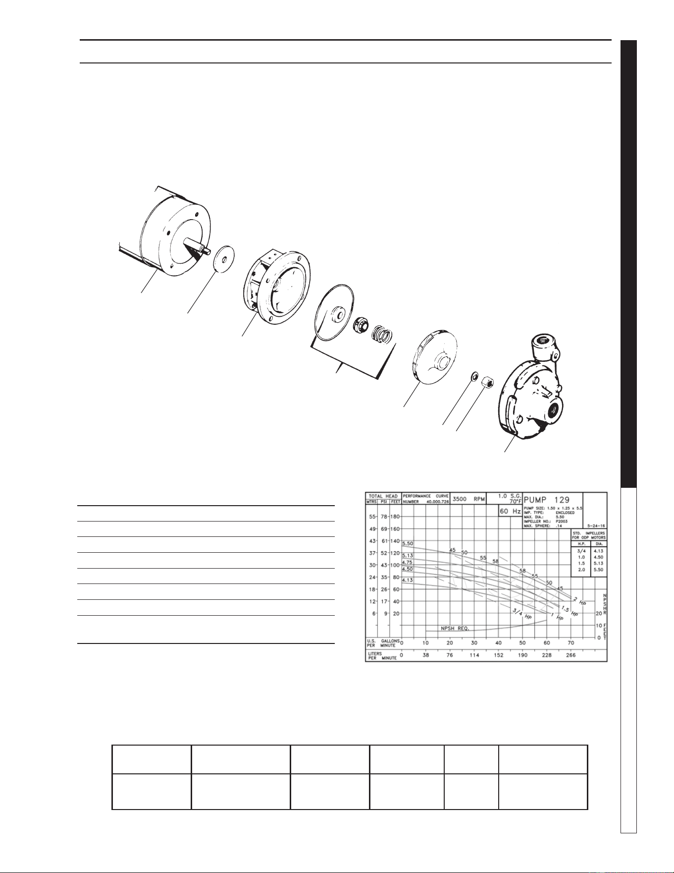
TRANSFER PUMP EXPLODED VIEW PARTS LIST
#8.756-757.0 • 1.5 HP • 115/230V • 1PH
1
2
3
4
5
6
7
8
MODEL NO.
SIZE
INLET OUTLET AMPS VOLTS PHASE MAXGPM, PSI
129 1-1/2" 1-1/4" 6.8, 3.4 115/230 1
See Chart
Above
ITEM PART NO. DESCRIPTION QTY
1 Washer 1
2 Base 1
3 Seal 1
4 5.375 Impeller 1
5 Washer 1
6 Nut 1
7 Head 1
8 Motor, 1-1/2 HP 115/230
1 PH 1
Water Maze REC2-20 • 8.917-436.0 - E
OPERATOR’S MANUAL WATER TREATMENT SYSTEM
34
89174360-11
Prewired
by
Manufacturer
JUNCTION BOX WIRING DIAGRAM
Storage
Tank
Low Float
Storage
Tank
Fresh
Water Fill
Storage
Tank
High Float
Infeed
Tank
Float
OPEN
OPEN
OPEN
OPEN
Bottom prewired by manufacturer
Water Maze REC2-20 • 8.917-436.0 - E
35
WATER TREATMENT SYSTEM
OPERATOR’S MANUAL
OZONE GENERATOR
Ozone…Nature's Purifi cation Agent
Ozone is produced in nature or artifi cially by man. In
the Earth's atmosphere, ozone is formed when oxygen
is exposed to ultraviolet light or an electrical charge as
during thunderstorms. Ozone's primary function in na-
ture is to purify the air we breathe and screen us from
harmful rays of the sun. In a similar fashion, Water Maze
systems use ozone to disinfect water because ozone
has a number of characteristics that make it ideal for
water treatment.
Ozone's Characteristics:
Ozone is well suited for water treatment and its unique
characteristics are described below:
■ Ozone works up to 3,000 times faster than chlorine
to kill bacteria and destroy harmful microorgan-
isms.
■ Ozone is a more powerful oxidizing agent than
chlorine and bromine and has a better ability to
remove water contamination.
■ Ozone will not form harmful by-products, like
THM's (a problem with drinking water) or chlo-
ramines (by-product of chlorine responsible for
odors, skin irritations and burning eyes).
■ Ozone will not alter the water's pH, thereby reduc-
ing pH fl uctuations.
■ Ozone coagulates small particles in water so clar-
ity is dramatically improved.
■ Ozone acts as a deodorizer removing unpleasant
odors from water.
How the Water Maze Ozone System
Works:
Because ozone is unstable, it cannot be packaged and
used at a later date. For this reason, ozone is always
produced where utilized.
Point-of-use-ozone generation is simple. This powerful
disinfectant is produced from ambient air surrounding the
generator using special ultraviolet lamps located inside
the system's cabinet. To generate the ozone, air move-
ment is created through the use of an air compressor or
water venturi. As air passes over these unique lamps,
the oxygen contained in the air is converted. The result-
ing ozone gas is subsequently introduced to the water
in the inlet pipeline, where oxidation and disinfection
immediately take place.
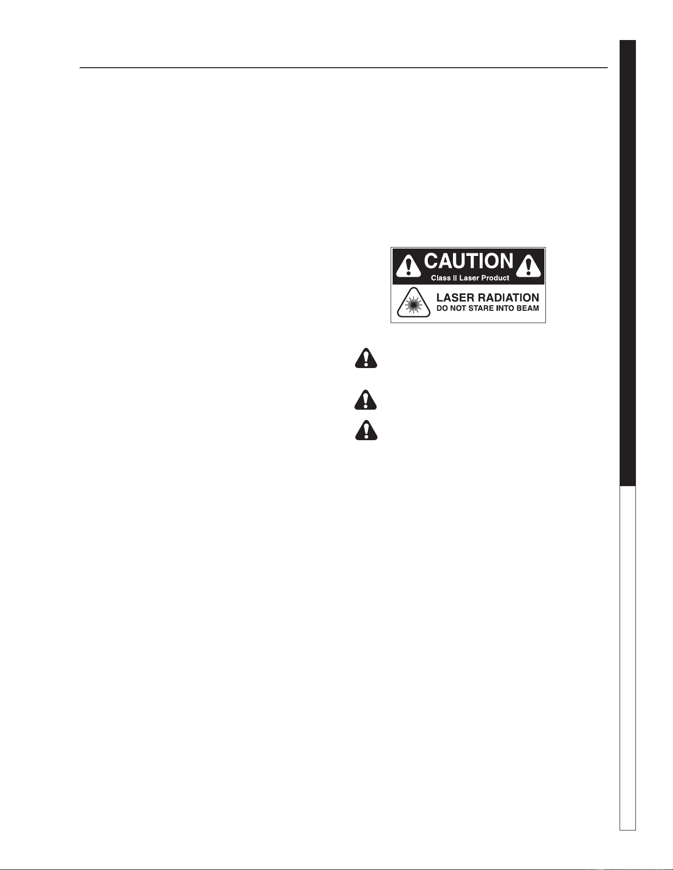
OZONE GENERATOR OPERATOR’S MANUAL
ULTRAVIOLET LIGHT
COMPLIANCE
Ultraviolet Light Safety Requirements
The device used in this product is a Class 1 certifi ed
ozone generator product. Operating this product outside
specifi cations or altering its original design may result
in hazardous radiation exposure, and may be consid-
ered an act of modifying or new manufacturing of a laser
product under U.S. regulations contained in 21CFR
Chapter 1, subchapter J.
CAUTION: Avoid exposure to direct or
strongly refl ected germicidal ultraviolet
rays. DO NOT STARE INTO BEAM.
DANGER: Ultraviolet radiation. Disconnect
Power Before Replacing Lamp.
DANGER: Connect only to a circuit that is
protected by Ground Fault Circuit Interrupt
(GFCI).
Instructions for disposing of your UV
Light Tube
1. Do not break a UV Light Tube. Keep all tubes whole
if possible. If a UV Light Tube is accidentally broken,
wear gloves while picking up the pieces, and care-
fully dispose of them in a trash bag. Wipe the area
with a wet wipe, and put the wet wipe in the same
trash bag. Place the trash bag with broken pieces
inside another trash bag. Mark the bag with a sign
labeled, "Broken Mercury Light Bulb".
2. Remove the UV Light Tube from the Ozone Genera-
tor. Place the used tube in the trash bag, and place
that bag inside another trash bag. Seal the openings
and then tape a slip of paper on the outer bag labeled,
"Mercury LIght Bulb."
3. Take the used and /or broken mercury tube to your
nearest recycling bin for mercury light bulbs..or
take this tube to a state-approved recycling center.
Water Maze REC2-20 • 8.917-436.0 - E
OPERATOR’S MANUAL WATER TREATMENT SYSTEM
36
OZONE GENERATOR OPERATOR’S MANUAL
OZONE GENERATOR
MAINTENANCE:
WARNING: Never look at an
unshielded ozone lamp while
operating the unit. This lamp
will cause severe eye and skin
damage. There is a green indi-
cator light which will dim when
the unit is operating properly
and will turn bright green if
there is a malfunction. See
product description for location
of the indicator light.
Lamp:
The light has a 9,000 hour life expectancy.
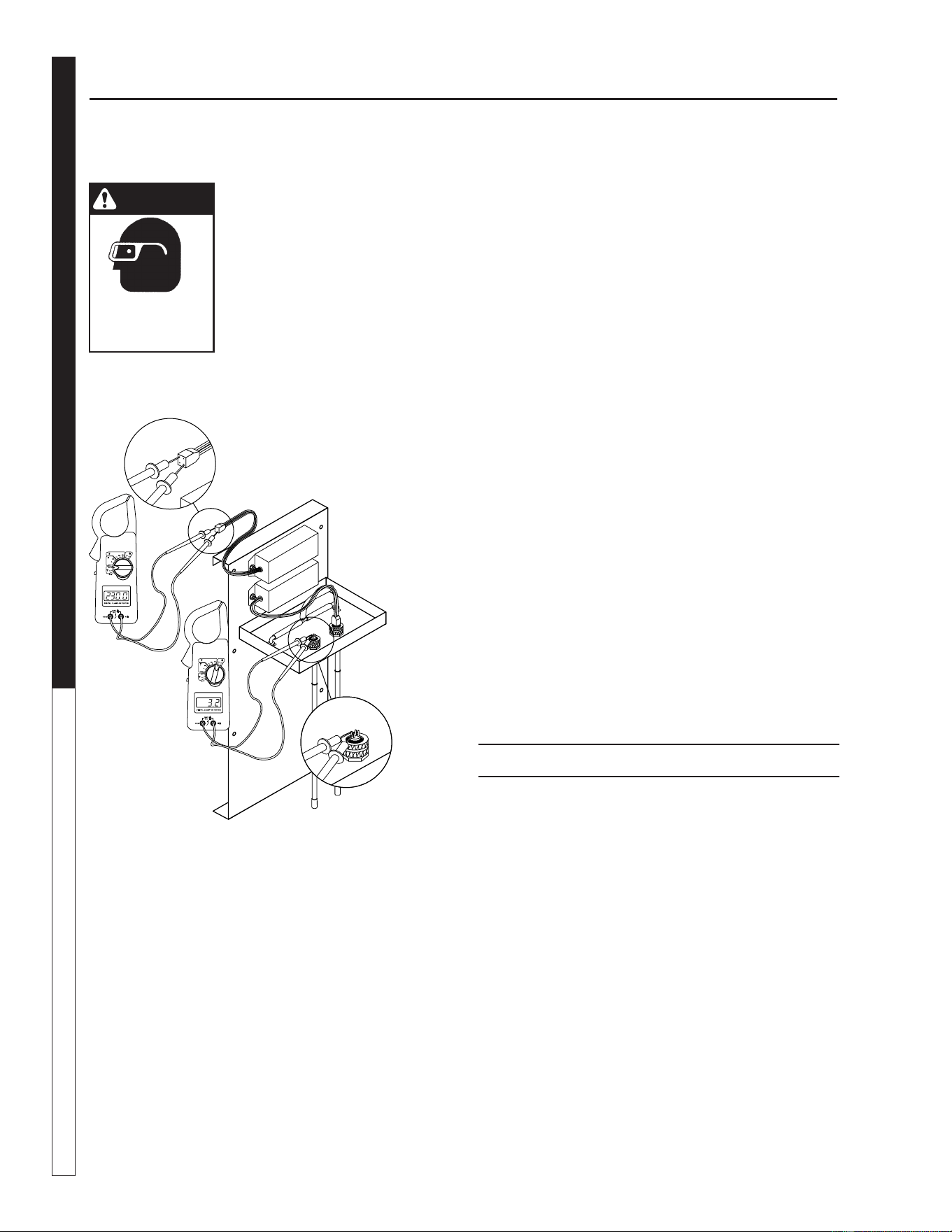
Testing the Lamp:
To test the ozone lamp use a voltmeter set on ohms.
First, remove the ozone cover and unplug the lamp
plug from the ozone lamp. NOTE: There are two fi la-
ments - an upper and a lower - inside the lamp. Place
one of the voltmeter leads on one of the lamp prongs
and, with the other lead, touch all of the three remain-
ing prongs. If continuity is not achieved on both upper
and lower fi laments, replace the ozone lamp (Part
#6-0534). (See fi gure 2 below.)
WARNING
EYE HAZARD:
NEVER LOOK
AT UNSHIELDED
OZONE LAMP
LAMP TESTING PROCEDURE
Figure 2
Testing the Ballast:
To test the power pack, use a voltmeter set on the cor-
rect voltage (230V). Place one of the voltmeter leads
into the lamp plug where the white wire goes into it
and plug the other voltmeter lead into the lamp plug
where the blue wire goes into it. If no voltage is pres-
ent, replace the ozone ballast (Part # 8.716-590.0) If
the voltage tests out right and the bulb is good, but
the bulb will still not turn on, replace the ballast. The
internal starter in the ballast has gone bad.
Replacing the Lamp:
Lamps are available from your Water Maze Dealer
should it need to be replaced. Simply turn off the
power, remove the screws on the power pack cover
and remove the cover. Disconnect the plug on the
end of the ozone lamp. Now, loosen the lamp holder
locking ring from around the end of the lamp by turn-
ing it counterclockwise and removing it. Remove the
lamp by grabbing the rubber bushing around the end
of the lamp and pulling it straight out. Remove the
rubber bushing from the lamp and install it on your
new lamp making sure the outer edge of the bushing
is fl ush with the outer edge of the silver end cap on
the lamp. Now, slide the lamp back into the reaction
chamber. The lamp holder may now be reinstalled and
tightened. Reinstall the plug onto the lamp and replace
the power pack cover.
CAUTION: Keep the lamp free of fi ngerprints and
dust particles by only handling the metal end caps
on the lamp. You can clean the lamp with rubbing
alcohol and a soft cloth. A dirty lamp will not allow
maximum ozone output.
SPECIFICATIONS:
Energy required:
230VAC max., 800 Amp/Ballast
Power Consumption:
20 Watts
Average Lamp Life:
9,000 Hours
Lamp Wavelength:
185nm
Water Maze REC2-20 • 8.917-436.0 - E
37
WATER TREATMENT SYSTEM
OPERATOR’S MANUAL
89174360-13
O
Z
ONE GENER
ATOR
DISCONNECT F
R
OM ELECTRICAL
SUPP
LY BEFORE SE
R
VICING.
DESCONECTE LA CORRIENTE ELECTRICA
ANTES DE D
AR SER
VICI
O
.
COUPER
L
’ALIMEN
TA
TION ÉLECTRI
Q
UE
AV
ANT DE
F
AIRE UNE RÉ
P
ARATION.
DISCONNECT F
R
OM ELECTRICAL
SUPP
LY BEFORE SE
R
VICING.
DESCONECTE LA CORRIENTE ELECTRICA
ANTES DE D
AR SE
R
VICI
O
.
COUPER
L
’ALIMEN
TATION ÉLECTRIQ
UE
AV
ANT DE
FAIRE UNE RÉ
P
AR
ATION .
INDICATOR L
IGHT OPERAT
I
O
N
A b
r
ight conti
n
uous light indicates UV
light or ballast de
f
ectiv
e
.
Una luz luminosa indica que la luz ult
ra-
violeta o t
rans
f
o
rmador está de
f
ectuos
o
.
Une lumière claire indique que la lumière
ultraviolette ou le tr
ansf
ormateur est
défectueux.
OPER
ACION DE LA LUZ
INDICADORA
OPÉR
ATION DE LE LAMPE
INDIC
A
TEUR
HOT!
C
ALIENTE!
C
H
A
UD!
C
A
UTION
PREC
A
UCION
A
TTENTION
8.900-455.0
!
W
ARNING!
AT
ENC
IO
N
!
/
A
TT
ENTI
ON
!
!
OZONE GENERATOR
EXPLODED VIEW
(8.905-715.0)
19
11
14
5
5
9
23
10
4
1
15
3
22
21
14
12
17
17
2
13
6
14
24
7
20
18
25
8
16
OZONE GENERATOR OPERATOR’S MANUAL

Water Maze REC2-20 • 8.917-436.0 - E
OPERATOR’S MANUAL WATER TREATMENT SYSTEM
38
OZONE GENERATOR OPERATOR’S MANUAL
OZONE GENERATOR
EXPLODED VIEW PARTS LIST
ITEM PART NO. DESCRIPTION QTY
1 8.913-357.0 Ozone Box, Back, 400 1
2 8.913-360.0 Ozone Box, Front, 400 1
3 9.802-455.0 Light, Indicator, Green 4
4 9.802-523.0 Locknut, 3/4" Conduit 4
5 8.716-583.0 Connector, Aluminum Cord
SCH1037 4
6 8.707-355.0 Ozone Check Valve 1
7 8.716-600.0 Lamp, Ozone Replacement 4
8 8.900-455.0 Label, Ozone Generator 1
9 9.802-696.0 Nut, 10/32", NF ST ST KEP 12
10 8.706-570.0 Locknut, 3/8", Nylon 2
11 8.706-585.0 Connector, 3/8" x 3/8",
Male Elbow (Poly) 2
12 8.706-594.0 Tee, 3/8" Poly 1
13 8.706-733.0 Bushing, 1/2" Snap 1
14 8.711-733.0 Tubing, 3/8" x 1/2", Vinyl 6
15 9.802-423.0 Cord, Service, SEO,
16/3 /ft. 8
16 9.802-453.0 Switch, Curvette, 120V & 220V 1
17 9.802-515.0 Strain Relief, 1/2" NPT
Ozone Gen 1
18 8.706-545.0 Cushion, 1/2", 13-3/4" x 5-3/4",
Rubber, 400 1
19 8.913-358.0 Ozone Box, Top, 400 1
20 8.913-359.0 Ozone Box, Bottom, 400 1
21 8-716-590.0 Ballast, 120/240V,
Ozone Generator 4
22 9.804-566.0 Screw, 10/32" x 1/2" Slot Pan
MS ZN 12
23 8.718-968.0 Washer, 10 x SAE ZN 12
24 9.802-798.0 Screw, #10 x 1/2"
Tek Hex Head 8
25 8.900-511.0 Label,
220V, Ozone Generator
1

Water Maze REC2-20 • 8.917-436.0 - E
WATER TREATMENT SYSTEM
WARRANTY
WARRANTY
ACCESSORIES AND PARTS WARRANTY
LIMITED MINIMUM 90 DAY WARRANTY
We warrant to the original consumer that each new part and accessory sold by Watermaze will be free from
manufacturing defects in materials or workmanship in normal service for the duration specifi ed by the original
component manufacturer with a 90 day minimum from date of purchase, provided it is installed properly and
the equipment is maintained in accordance with Watermaze instructions and manuals. Components manufac-
tured by Watermaze such as frames, and handles have a 2 year warranty from date of purchase.
Our obligation under this warranty is expressly limited as to the replacement or repair, at our option, at
Watermaze Camas, Washington 98607, or at a service facility designated by us, for such part or parts as
inspection shall disclose to have been defective.
EXCLUSIONS:
This warranty does not apply to defects caused by casualty or unreasonable use, including faulty repairs by
others and failure to provide reasonable and necessary maintenance.
LIMITATION OF LIABILITY
Watermaze's liability for special, incidental, or consequential damages is expressly disclaimed. In no event
shall Watermaze liability exceed the purchase price of the product in question. Watermaze makes every effort
to ensure that all illustrations and specifi cations are correct, however, these do not imply a warranty that the
product is merchantable or fi t for a particular purpose, or that the product will actually conform to the illustra-
tions and specifi cations. Our obligation under this warranty is expressly limited at our option to the replacement
or repair at a service facility or factory designated by us, of such part or parts as inspection shall disclose to
have been defective. THE WARRANTY CONTAINED HEREIN IS IN LIEU OF ALL OTHER WARRANTIES,
EXPRESS OR IMPLIED, INCLUDING ANY IMPLIED WARRANTY OF MERCHANTABILITY OR FITNESS
FOR A PARTICULAR PURPOSE ARE EXPRESSLY LIMITED TO THE DURATION OF THIS WRITTEN
WARRANTY. This warranty gives you specifi c legal rights and you may also have other rights which vary from
state to state. Watermaze does not authorize any other party, including authorized Watermaze Distributors,
to make any representation or promise on behalf of Watermaze, or to modify the terms, products conforms to
local codes, While Watermaze attempts to assure that its products meet national codes, it cannot be respon-
sible for how the customer chooses to use or install the product. Some states do not allow limitations on how
long an implied warranty lasts or the exclusion or limitation of incidental or consequential damages, so the
above limitation or exclusion may not apply to you.
TO OBTAIN WARRANTY SERVICE:
Purchaser must bring the accessory parts to an authorized Watermaze Distributor. For the distributor nearest
you consult our web page: www.wmaze.com or write: Watermaze, 4275 NW Pacifi c Rim Blvd, Camas, WA
98607.

WATER TREATMENT SYSTEM
WARRANTY
LIMITED NEW PRODUCT WARRANTY
WASH WATER / WATER TREATMENT SYSTEMS
WHAT THIS WARRANTY COVERS
All
WATER MAZE
water treatment systems are warranted by to the original purchaser to be free from defects in materials
and workmanship under normal use, for the periods specified below. This Limited Warranty, subject to the exclusions shown
below, is calculated from the date of the original purchase, and applies to the original components only. Any parts replaced
under this warranty will assume the remainder of the part’s warranty period. A 60 day grace period will be given for installa-
tion.
ONE YEAR PARTS AND 30 DAY LABOR WARRANTY:
All components excluding normal wear items as described below.
WARRANTY PROVIDED BY OTHER MANUFACTURERS:
Motors, which are warranted by their respective manufacturers, are serviced through these manufacturers’ local authorized
service centers.
WATER MAZE
cannot provide warranty on these items.
WHAT THIS WARRANTY DOES NOT COVER
This warranty does not cover the following items:
1. Normal wear items, such as seals, filters, gaskets, O-rings, packings, pistons, brushes, filtering media, ozone
bulbs, sensors, UV scanners, oil-skimmer belt, impedance sensor. Minor leaks covered first time on original start-
up only.
2. Damage or malfunctions resulting from accidents, abuse, modifications, alterations, incorrect installation, improper
servicing, failure to follow
manufacturer’s maintenance instructions, or use of the equipment beyond its stated
usage specifications as contained in the operator’s manual.
3. Damage due to freezing, sludge build-up, chemical deterioration (oxidation, chloride or fluoride corrosion), and
rust.
4. Damage to components from fluctuations in electrical or water supply.
5. Normal maintenance service, including adjustments.
6. Transportation to service center, field labor charges, or freight damage.
7. Consumables and water quality.
WHAT YOU MUST DO TO OBTAIN WARRANTY SERVICE
While not required for warranty service, we request that you register your
WATER MAZE
Product by returning the com-
pleted registration card. In order to obtain warranty service on items warranted by
WATER MAZE
, you must return the
product to your Authorized
WATER MAZE
Dealer, freight prepaid, with proof of purchase, within the applicable warranty
period. If the product is permanently installed, you must notify your Authorized
WATER MAZE
Dealer of the defect. Your
Authorized
WATER MAZE
Dealer will file a claim with
WATER MAZE
, who must subsequently verify the defect. In most
cases, the part must be returned to
WATER MAZE
freight prepaid with the claim. For warranty service on components
warranted by other manufacturer’s, your Authorized
WATER MAZE
Dealer can help you obtain warranty service through
these manufacturers’ local authorized service centers.
LIMITATION OF LIABILITY
WATER MAZE’S
liability for special, incidental, or consequential damages is expressly disclaimed. In no event shall
WATER MAZE’S
liability exceed the purchase price of the product in question.
WATER MAZE
makes every effort to ensure
that all illustrations and specifications are correct, however, these do not imply a warranty that the product is merchantable
or fit for a particular purpose, or that the product will actually conform to the illustrations and specifications. Our obligation
under this warranty is expressly limited at our option to the replacement or repair at a service facility or factory designated
by us, of such part or parts as inspection shall disclose to have been defective. THE WARRANTY CONTAINED HEREIN
IS IN LIEU OF ALL OTHER WARRANTIES, EXPRESS OR IMPLIED, INCLUDING ANY IMPLIED WARRANTY WATER
QUALITY, MERCHANTABLIITY OR FITNESS FOR A PARTICULAR PURPOSE ARE EXPRESSLY LIMITED TO THE
DURATION OF THIS WARRANTY.
This warranty gives you specific legal rights and you may also have other rights which
vary from state to state.
WATER MAZE
does not authorize any other party, including authorized
WATER MAZE
Distributors,
to make any representation or promise on behalf of
WATER MAZE
, or to modify the terms, conditions, or limitations in any
way. It is the buyer’s responsibility to ensure that the installation and use of
WATER MAZE
products conforms to local
codes. While
WATER MAZE
attempts to assure that its products meet national codes, it cannot be responsible for how the
customer chooses to use or install the product. Some states do not allow limitations or exclusion or limitation of incidental or
consequential damages, so the above limitation or exclusion may not apply to you.


Form #8.917-436.0 • Printed in U.S.A.