Invert Extend N Go
SF-BH6719
USER MANUAL
IMPORTANT! Please retain owner’s manual for maintenance and adjustment instructions.
Your satisfaction is very important to us, PLEASE DO NOT RETURN UNTIL YOU HAVE
CONTACTED US: [email protected] or 1- 877 - 90SUNNY (877-907-8669).

1
IMPORTANT SAFETY INFORMATION
We thank you for choosing our product. To ensure your safety and health, please use this
equipment correctly. It is important to read this entire manual before assembling and using the
equipment. Safe and effective use can only be achieved if the equipment is assembled,
maintained and used properly. It is your responsibility to ensure that all users of the equipment
are informed of all warnings and
precautions.
1. Before starting any exercise program, you should consult your physician to determine if you
have any medical or physical conditions that could put your health and safety at risk, or
prevent you from using the equipment properly. Your physician’s advice is essential if you are
taking medication that affects your heart rate, blood pressure or cholesterol level.
2. Be aware of your body’s s
ignals. Incorrect or excessive exercise can damage your health.
Stop exercising if you experience any of the following symptoms: pain, tightness in your chest,
irregular heartbeat, shortness of breath, lightheadedness, dizziness or nauseous feeling. If
you do experience any of these conditions, you should consult your physician before
continuing with your exercise program.
3. Keep children and pets away
from the equipment. The equipment is designed for adult use
only.
4. Use the equipment on a solid, flat level surface with a protective cover for your floor or carpet.
To ensure safety, the equipment should have at least 4 feet (1.2 M) of free space all around it.
5. Ensure that all nuts and bolts are securely tightened before using the equipment. The safety of
the equipment can only be maintained if it is regularly examined for damage and/or wear and
tear.
6. Always use the equipment as indicated. If you find any defective components while
assembling or checking the equipment, or if you hear any unusual noises coming from the
equipment during exercise, discontinue use of the equipment immediately and do not use until
the problem has been rectified.
7. Wear suitable clothing while using the equipment. Avoid weari
ng loose clothing that may
become entangled in the equipment.
8. Do not place fingers or objects into the moving parts of the equipment.
9. The maximum weight capacity of this unit is 350 pounds (158 KG).
10.The equipment is not suitable for therapeutic use.
11.To avoid bodily injury and/ or damage to the product or property, proper lifting and moving are
required.
12.Your product is intended for use in c
ool and dry conditions. You should avoid storage in
extreme cold, hot or damp areas as this may lead to corrosion and other related problems.
13.This equipment is designed for indoor and home use only; it is not intended for commercial
use.
2
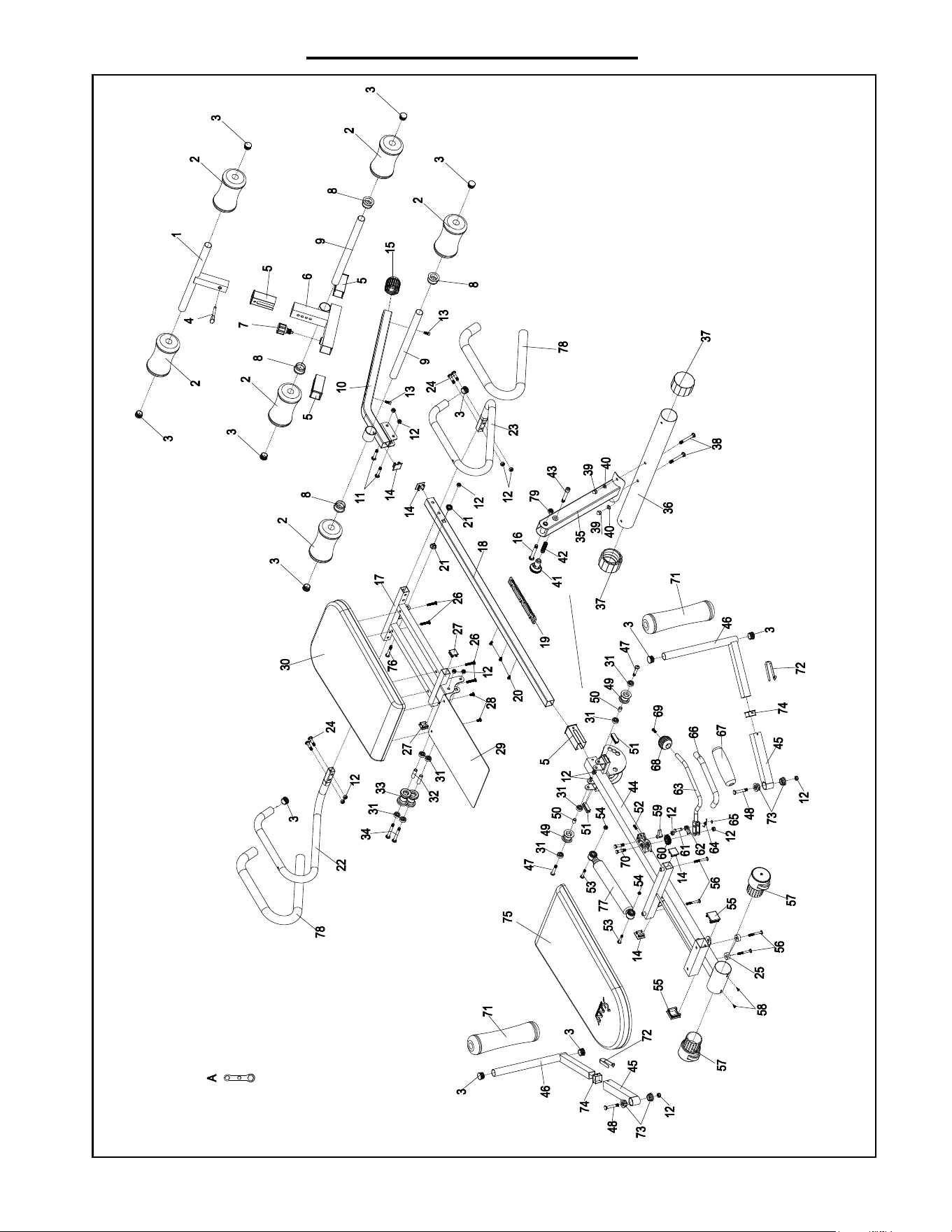
EXPLODED DIAGRAM
3
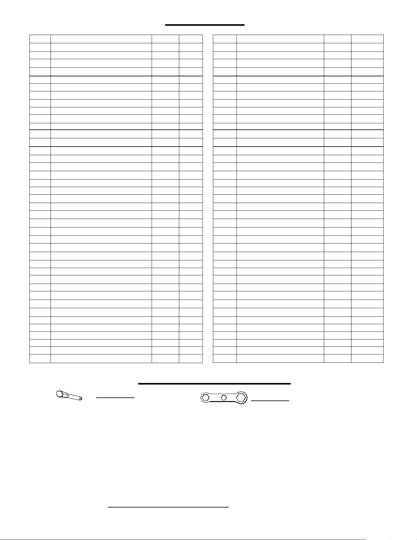
PARTS LIST
1 Hook Bar 1 41 Plastic Knob
1
2 Sponge 6 42 Spring
1
3 Cap 12 43 Bolt M10
1
4 Pin 1 44 Main Frame
1
5 Bushing 4 45 Handle Connect Tube
2
6 Hook Tube 1 46
Handle
2
7 Knob M16 1 47 Bolt M8
2
8 Sleeve 4 48 Bolt M8
2
9 Connecting Tube 2 49 Plastic Head
2
10 Support Tube 1 50 Casing
2
11
Bolt
M8
2
51
Eva Pad
2
12 Nut 15 52 Spring
1
13 Bolt M6 2 53 Bolt M6
2
14 Cap 4 54 Nut M6
2
15 Cap 1 55 Cap
2
16 Bolt M10 1 56 Bolt M6
4
17 Handle Connect Tube 1 57 Rear Cap
2
18 Main Frame Connect Tube 1 58 Bolt M4
2
19 Rack 1 59 Safety Buckle
1
20 Bolt M6 3 60 Gear
1
21 Spacer 2 61 Spacer
1
22 Handle-L 1 62 Safety Buckle
1
23 Handle-R 1 63 Adjustable Lever
1
24 Bolt M8 4 64 Spring
1
25 Rubber Pad 2 65 Washer
1
26 Bolt M6 4 66 Sponge
1
27 Cap 2 67 Sponge
1
28 Bolt M6 2 68 Grip
1
29 Partition 1 69 Bolt M6
1
30 Front Cushion 1 70 Bolt M8
2
31 Bearing 8 71 Spo
nge
2
32 Casing 2 72 Marble
2
33 Plastic Wheel 2 73 Sleeve
4
34 Bolt M8 2 74 Bushing
2
35 Front Support Tube 1 75 Rear Cushion
1
36 Front Tube 1 76 Bolt M8
1
37 Front Cap 2 77 Cylinder
1
38 Bolt M8 2 78 Sponge
2
39 Cap Nut 2 79 Nut M10
1
40 Washer M8 2 A Spanner
HARDWARE PACKAGE
#4 Pin 1pc
#A 1pc
No. No.Description DescriptionSpec. Spec.Qty. Qty.
Ordering Replacement Parts (U.S. and Canadian Customers only)
Please provide the following information in order for us to accurately identify the part(s) needed:
The model number (found on cover of manual)
The product name (found on cover of manual)
The part number found on the “EXPLODED DIAGRAM” and “PARTS LIST” (found near the
front of the manual)
Please contact
4
#39
#38
M8 2pcs
M8 2pcs
#24 M8 4pcs
#12 M8 4pcs
# 40 2pcs
# A
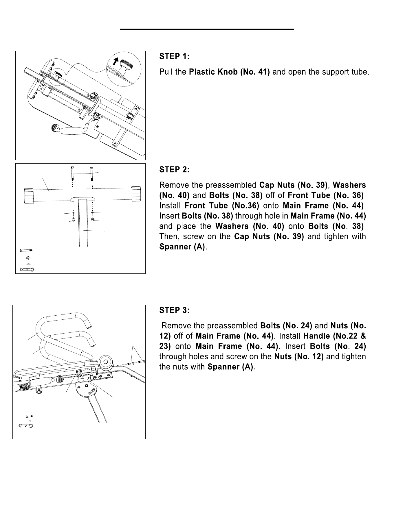
36
12
23
22
24
44
39
39
40
40
44
38
# A
ASSEMBLY INSTRUCTIONS
5
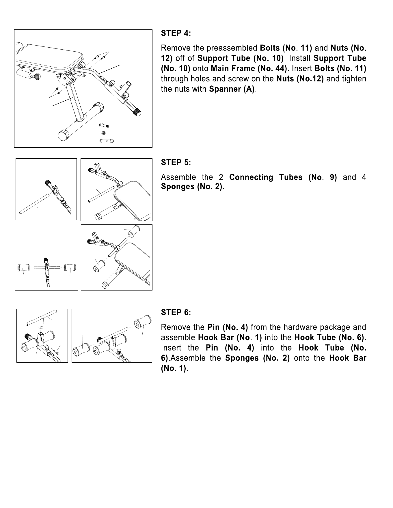
11
#11 M8 2pcs
#12 M8 2pcs
10
12
44
9
9
2
1
4
6
2
2
2
2
2
# A
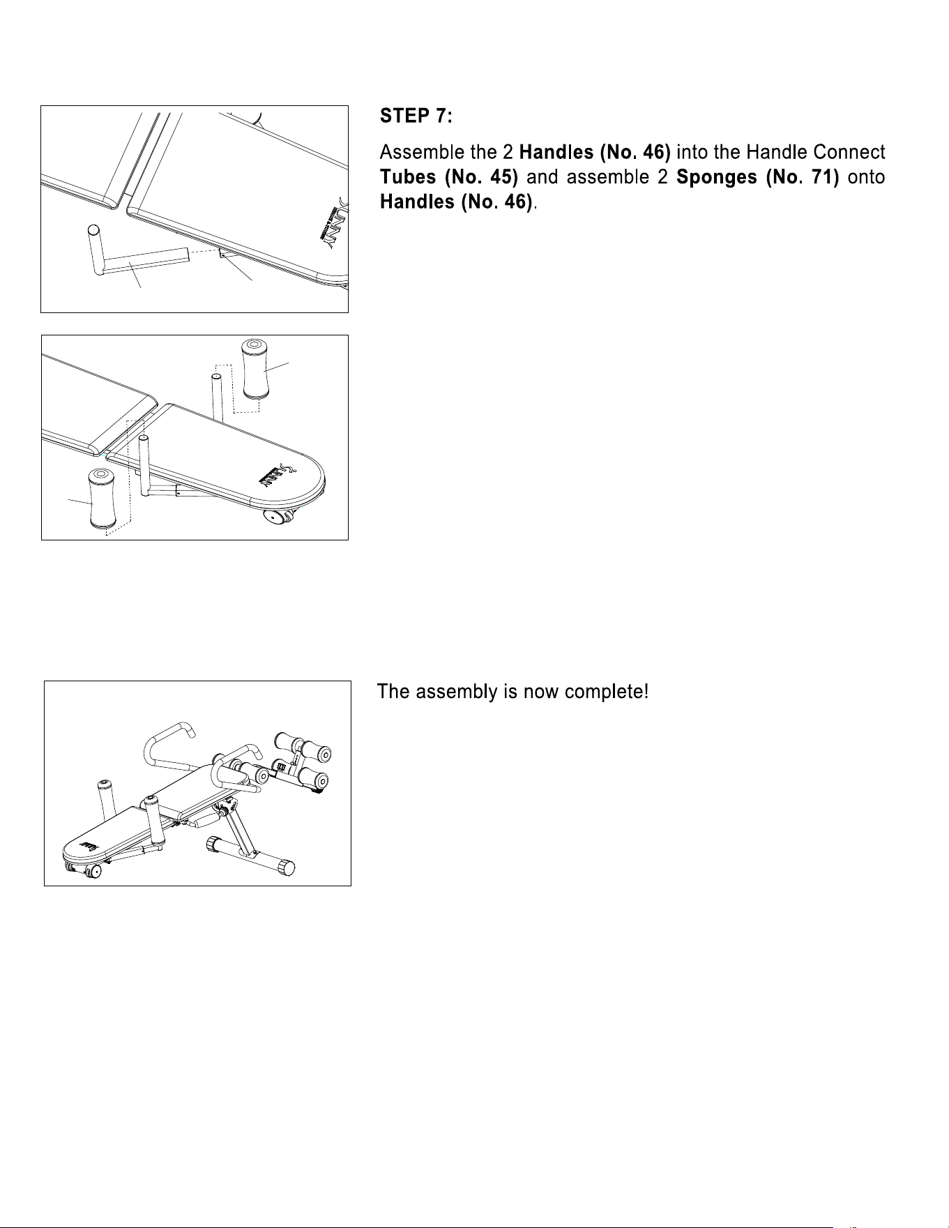
6
46 45
71
71
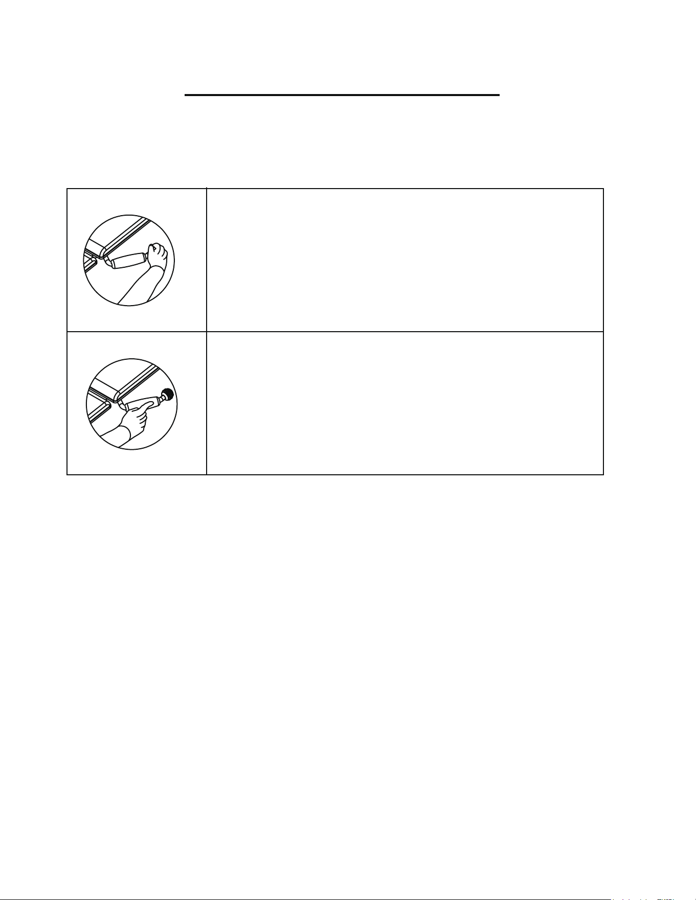
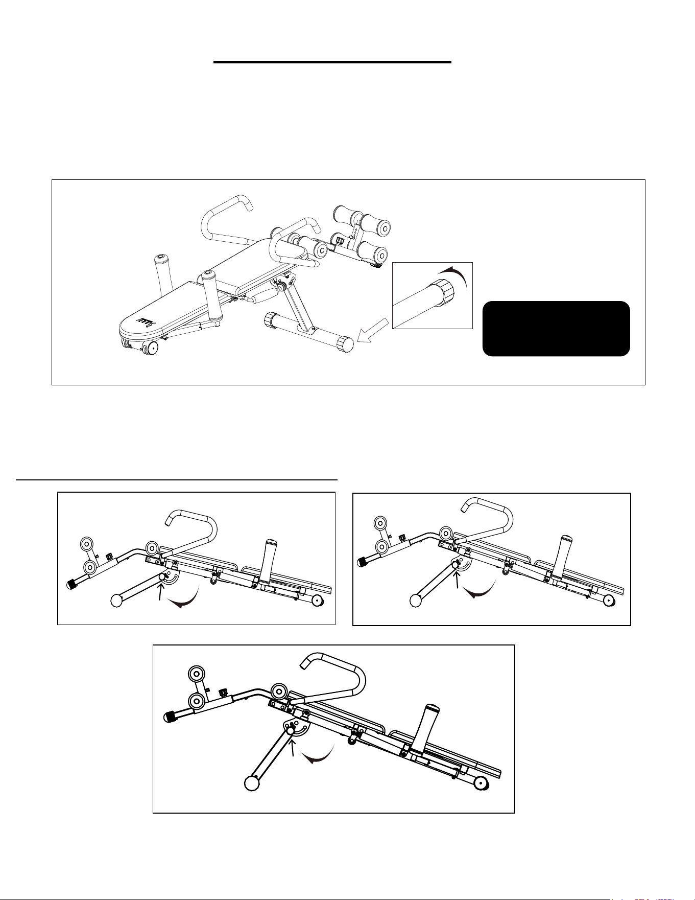
OPERATION INSTRUCTIONS
Hold the knob and pull back and forth to extend the bench.
Press the handle and hold to retract the bench.
7
8
ADJUSTING THE BALANCE
Before using the product, check
the balance of the product to ensure that it is safe for use. Put the product
on a flat, even surface. If you find that the product is slightly uneven, you may adjust the product to
compensate
for uneven ground. To do so, rotate the end caps on the
stabilizers until they're even with the
surface. Please refer to the drawing below.
ADJUSTING THE BENCH ANGLE
Turn knob to loosen. Pull knob to release, set
bench at the desired angle. Reinsert the knob and turn to tighten.
Keep hands clear of moving parts to avoid injury.
Please adjust the end caps if
there is a slight imbalance
problem caused by uneven ground.
ADJUSTMENT GUIDE
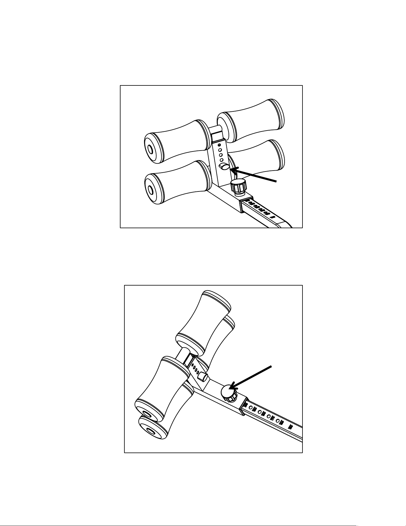
Pull the pin, there are four levels can be adjusted.
ADJUSTING THE SUPPORT TUBE
Turn knob to loosen. Pull knob to release and set the support tube at your desired level.
Insert the knob again and turn to tighten.
FOUR LEVELS FOR HOOK TUBE
9
Version
1.2
