
1
IMPORTANT SAFETY INFORMATION
We thank you for choosing our product. To ensure your safety and health, please use this
equipment correctly. It is important to read this entire manual before assembling and
using the equipment. Safe and effective use can only be achieved if the equipment is
assembled, maintained and used properly. It is your responsibility to ensure that all users
of the equipment are informed of all warnings and precautions.
1. Before starting any exercise program you should consult your physician to determine
if you have any medical or physical conditions that could put your health and safety at
risk, or prevent you from using the equipment properly. Your physician’s advice is
essential if you are taking medication that affects your heart rate, blood pressure or
cholesterol level.
2. Be aware of your body’s signals. Incorrect or excessive exercise can damage your
health. Stop exercising if you experience any of the following symptoms: pain,
tightness in your chest, irregular heartbeat, and extreme shortness of breath,
lightheadedness, dizziness or feelings of nausea. If you do experience any of these
conditions, you should consult your physician before continuing with your exercise
program.
3. Keep children and pets away from the equipment. The equipment is designed for
adult use only.
4. Use the equipment on a solid, flat level surface with a protective cover for your floor or
carpet. To ensure safety, the equipment should have at least 4 feet (1.2m) of free
space all around it.
5. Ensure that all nuts and bolts are securely tightened before using the equipment. The
safety of the equipment can only be maintained if it is regularly examined for damage
and/or wear and tear.
6. It is recommended that you lubricate all moving parts on a monthly basis.
7. Always use the equipment as indicated. If you find any defective components while
assembling or checking the equipment, or if you hear any unusual noises coming from
the equipment during exercise, stop using the equipment immediately and don’t use
the equipment until the problem has been rectified.
8. Wear suitable clothing while using the equipment. Avoid wearing loose clothing that
may become entangled in the equipment.
9. Do not place fingers or objects into moving parts of the exercise equipment.
10. The maximum weight capacity of this unit is 250 pounds (113kg).
11. The equipment is not suitable for therapeutic use.
12. You must take care of yourself when lifting and moving the equipment so as not to
injure your back. Always use proper lifting technique and seek assistance if necessary.
13. This equipment is designed for indoor and home use only! It is not intended for
commercial use!
29
10
26
18
16
25
27
32
15
9
21
33
31
7
23
13
20
31 33
20
12
29
26
26
13
8
29
21
33
1
31
31
33
2
8
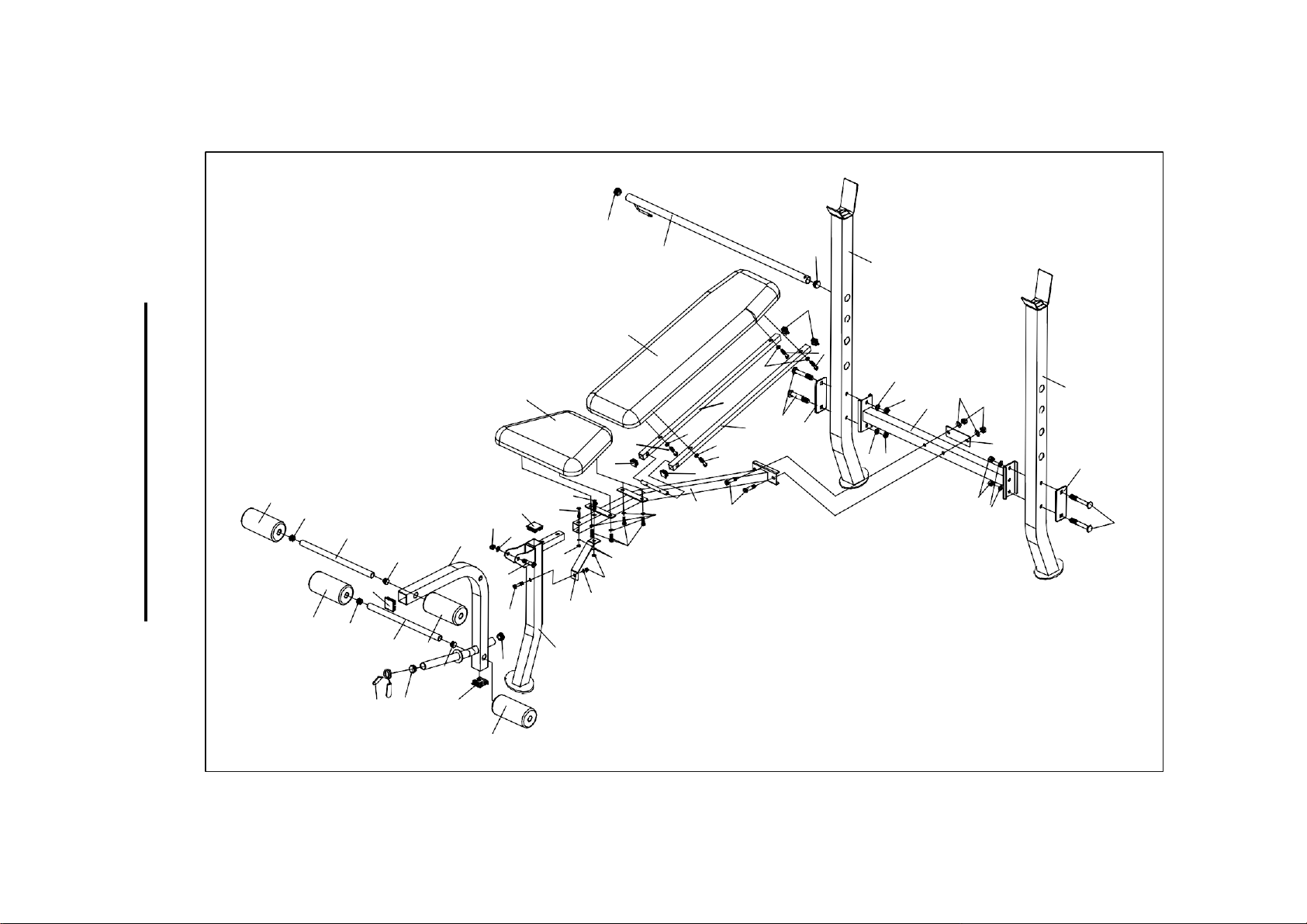
EXPLODED
DRAWING
2
6
18
1
20
11
17
15
16
24
29
3
22
33
31
7
17
18
5
19
18
16
17
15
15
4
28
17
30
30
32
3
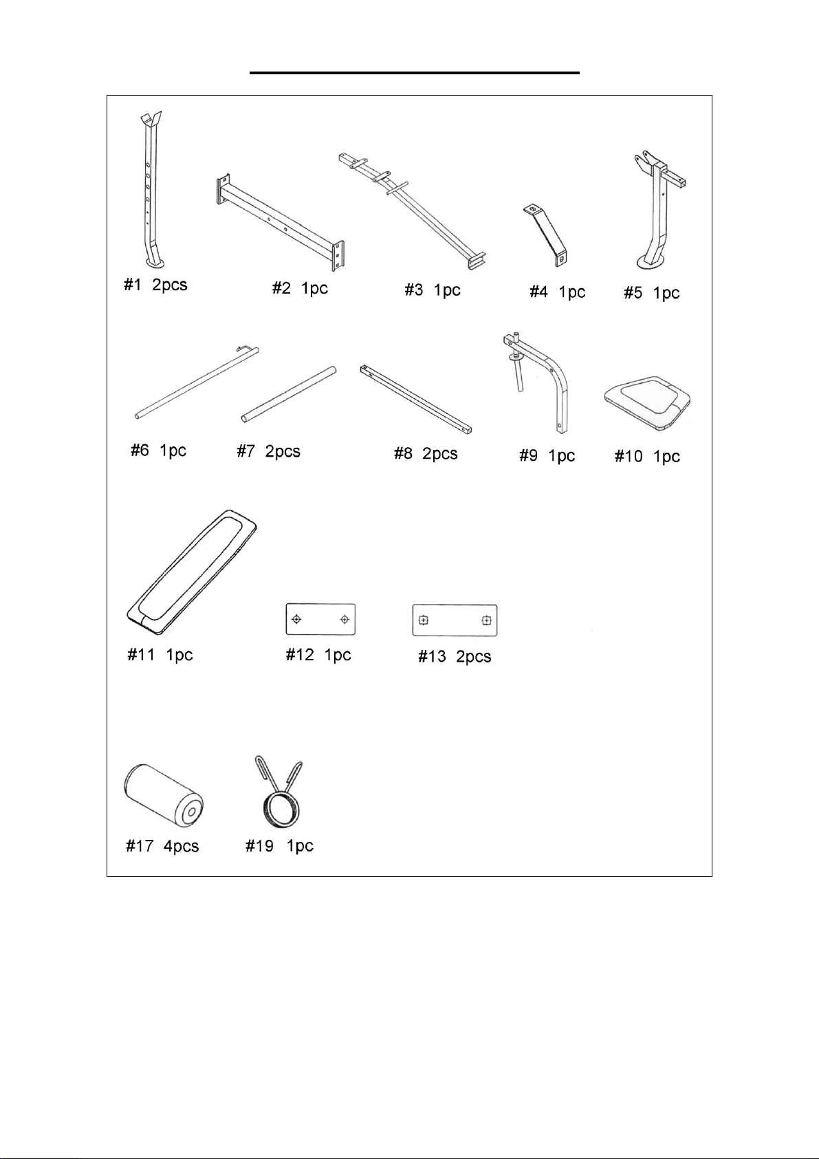
COMPONENT PARTS LIST

4
PARTS LIST
No.
Description
Qty
1
Upright Beam
2
2
Cross Brace
1
3
Main Seat Support
1
4
Diagonal Support
1
5
Front Post
1
6
Adjustable Backrest Bar
1
7
Foam Roller Bar
2
8
Backrest Support
2
9
Leg Developer
1
10
Seat Pad
1
11
Backrest Board
1
12
Bracket 4 3/8 x 3 3/8
1
13
Bracket 4 3/4 x 3 1/2
2
14
Spanner
2
15
End Cap ○3/4
4
16
End Cap 1 1/2 x 1 1/2
3
17
Foam Roll
4
18
End Cap ○1
4
19
Spring Clip ○1
1
20
End Cap 3/4 x 3/4
4
21
Carriage Bolt M10x2 5/8
4
22
Hex Bolt M10x2 1/8
2
23
Carriage Bolt M8x1 5/8
1
24
Carriage Bolt M8x1 3/4
1
25
Hex Bolt M10x2 3/8
1
26
Hex Bolt M6x1 3/8
4
27
Hex Bolt M6x5/8
4
28
Hex Bolt M8x2 1/8
1
29
Washer ○1/2
8
30
Washer ○5/8
3
31
Washer ○3/4
7
32
Aircraft Nut M8
3
33
Aircraft Nut M10
7
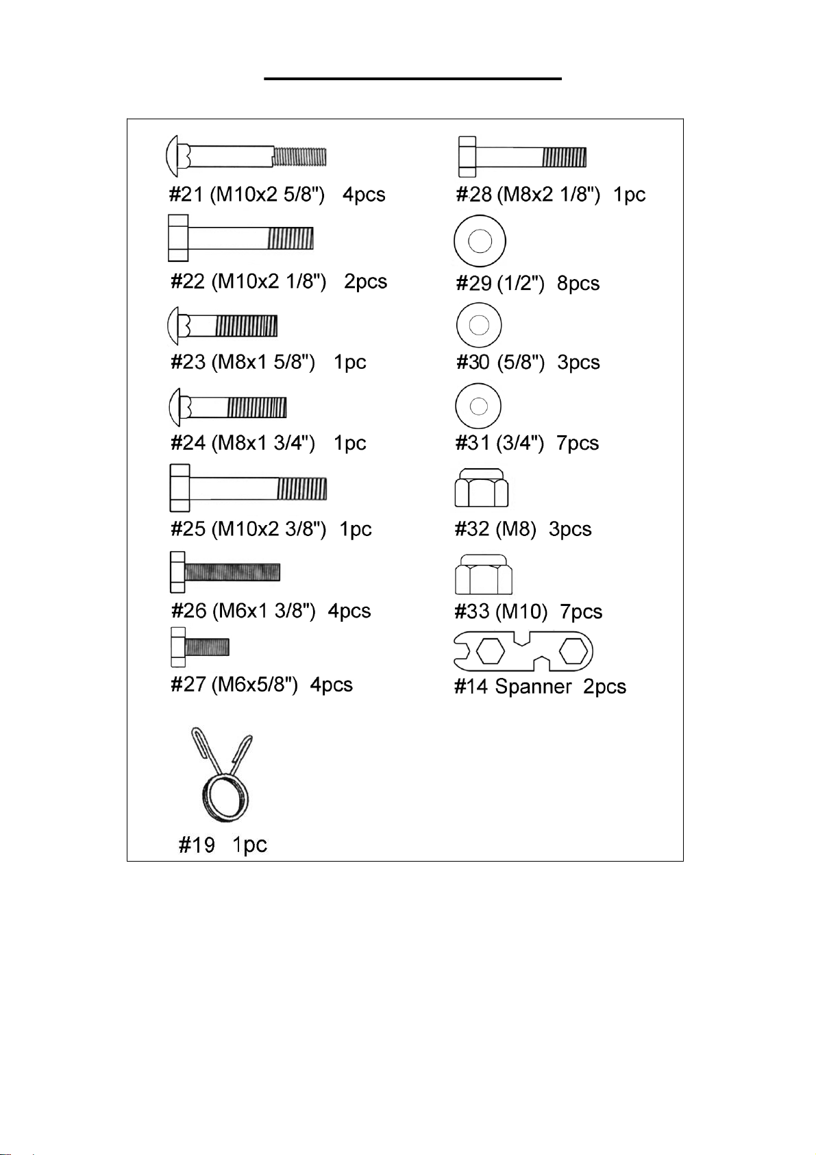
HARDWARE PACKAGE
Ordering Replacement Parts (U.S. and Canadian Customers only)
Please provide the following information in order for us to accurately identify the
part(s) needed:
✓ The model number (found on cover of manual)
✓ The product name (found on cover of manual)
✓ The part number found on the “EXPLODED DIAGRAM” and “PARTS
LIST” (found near the front of the manual)
Please contact us at [email protected] or 1- 877 - 90SUNNY
(877-907-8669).
5
6
ASSEMBLY INSTRUCTIONS
6
1
21
31
33
1
2
21
13
33
31
31
33
13
33
31
21
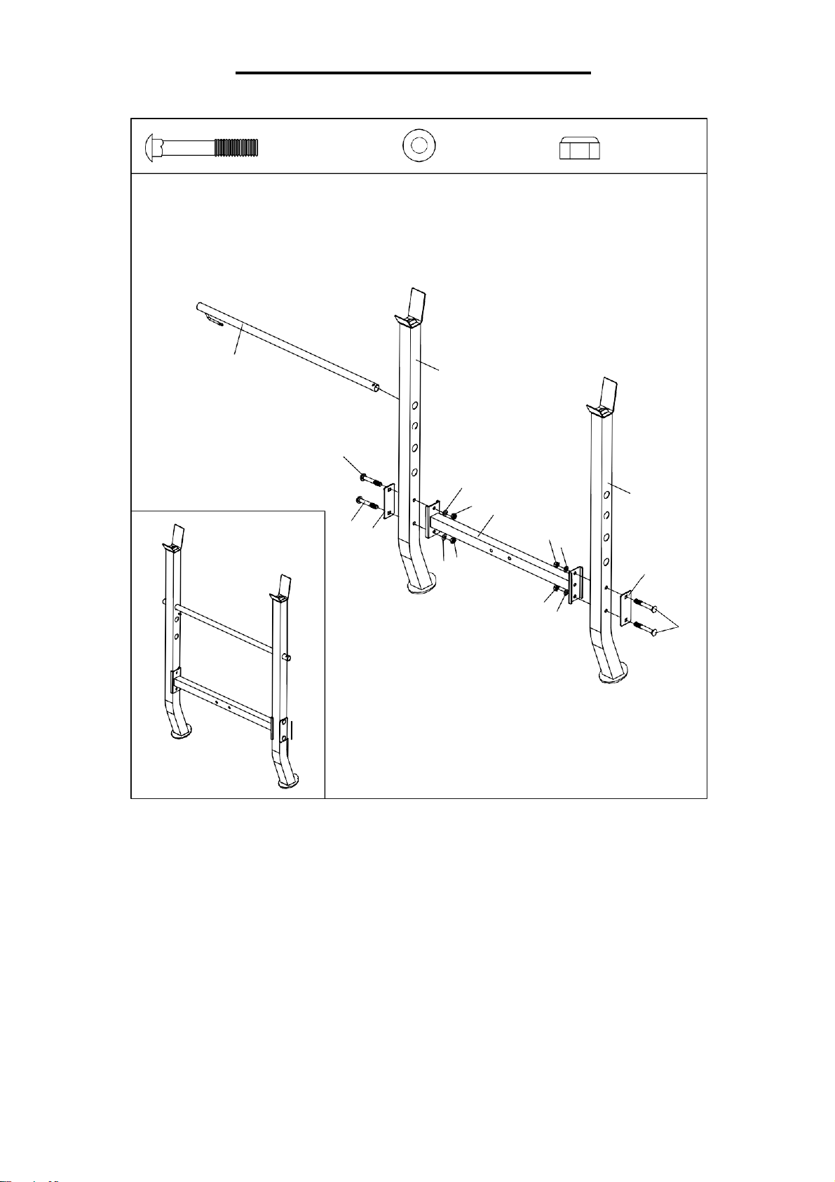
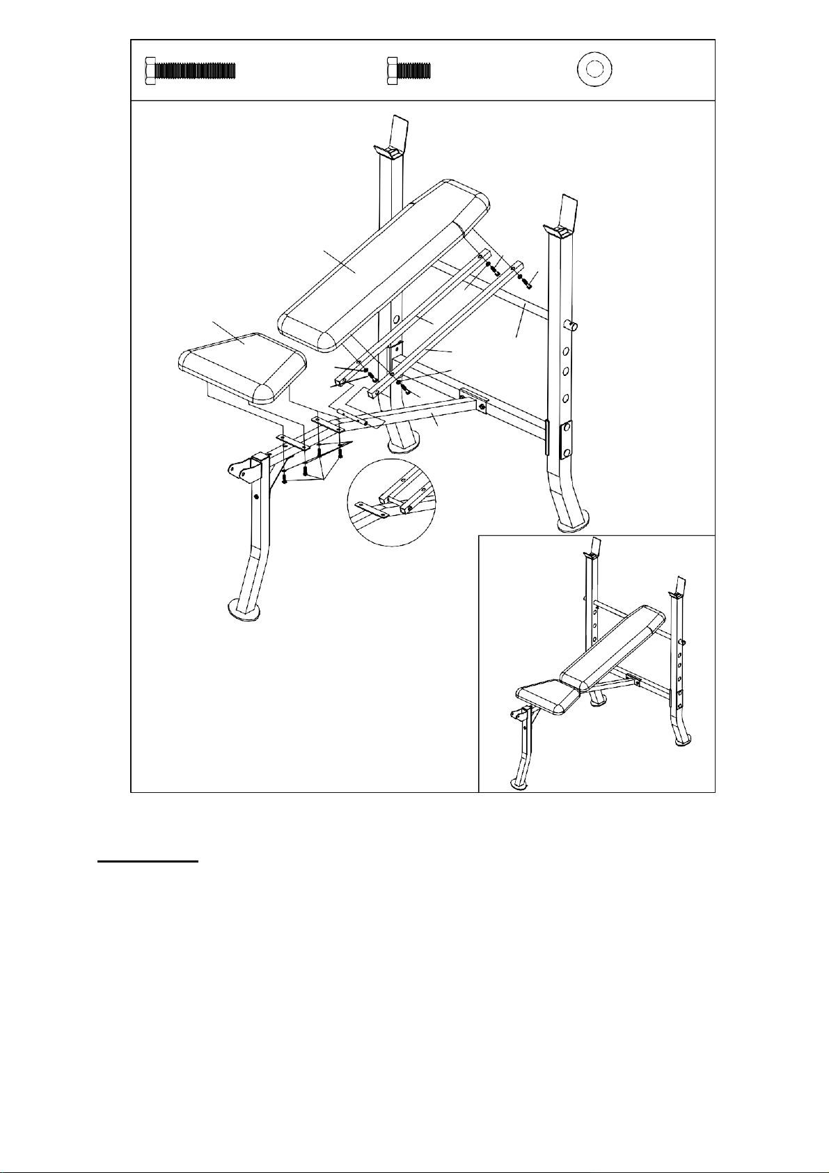
STEP 1:
Attach the Cross Brace (No. 2) to the Upright Beams (No. 1) using 2 Brackets (No. 13),
4 Carriage Bolts (No. 21), 4 Washers (No. 31) and 4 Aircraft Nuts (No. 33). Tighten
and secure with Spanner (No. 14).
Insert the Adjustable Backrest Bar (No. 6) through the holes located along the sides of
Upright Beams (No. 1). The position of the Adjustable Backrest Bar (No. 6) can be
adjusted depending on the preference of the user.
#21 (M10x2 5/8") 4pcs
#31 (3/4") (4pcs)
#33 (M10) (4pcs)
7
#22
#23
#26
(M10x2 1/8") 2pcs
(M8x1 5/8") 1pc
(M8x1 3/4") 1pc
#28
(M8x2 1/8") 1pc
#30 (5/8") (3pcs)
#31 (3/4") (2pcs)
#32
#33
(M8)
(M10)
(3pcs)
(2pcs)
2
31
33
12
24
23
30
3
22
22
32
30
32
28
4
30
5
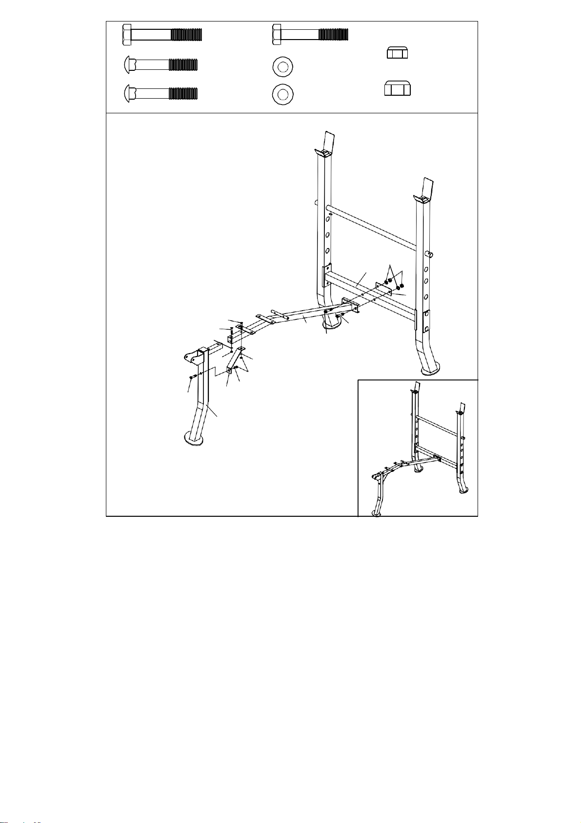
STEP 2:
NOTE: All nuts for this step should only be hand tightened until assembly is completed.
Attach the Main Seat Support (No. 3) to the Cross Brace (No. 2) using 2 Hex Bolts (No.
22), 1 Bracket (No. 12), 2 Washers (No. 31) and 2 Aircraft Nuts (No. 33).
Slide the Front Post (No. 5) into the bottom end of the Main Seat Support (No. 3) and
align the holes. Insert Carriage Bolt (No. 23) through the lower hole on the Main Seat
Support (No. 3) and secure using 1 Washer (No. 30) and 1 Aircraft Nut (No. 32).
Insert Carriage Bolt (No. 24) through the upper hole on the Main Seat Support (No. 3).
Fix one end of the Diagonal Support (No. 4) to the Carriage Bolt (No. 24) using 1
Washer (No. 30) and 1 Aircraft Nut (No. 32).
Fix the other end of the Diagonal Support (No. 4) to the Front Post (No. 5) using 1 Hex
Bolt (No. 28), 1 Washer (No. 30) and 1 Aircraft Nut (No. 32). Tighten and secure all
nuts using Spanner (No. 14).
8
11
26
26
29
10
8
29
8
6
29
29
26
26
29
3
27
STEP 3:
IMPORTANT: The Backrest Supports (No. 8) must first be attached to the bar located
on the Main Seat Support (No. 3) before continuing forward on this step.
Slide the bottom ends (with holes) of the Backrest Supports (No. 8) onto each side of
the bar located on the Main Seat Support (No. 3). Next, lean the top ends of the
Backrest Supports (No. 8) against the Adjustable Backrest Bar (No. 6).
Place the Backrest Board (No. 11) onto the Backrest Supports (No. 8), align the holes
and secure the Backrest Board (No. 11) using 4 Washers (No. 29) and 4 Hex Bolts
(No. 26). Tighten and secure with Spanner (No. 14).
Attach the Seat Pad (No. 10) to the Main Seat Support (No. 3) using 4 Washers (No.
29) and 4 Hex Bolts (No. 27). Tighten and secure with Spanner (No. 14).
#29 (1/2") (8pcs)
#27 (M6x5/8") 4pcs
#26 (M6x1 3/8") 4pcs
9
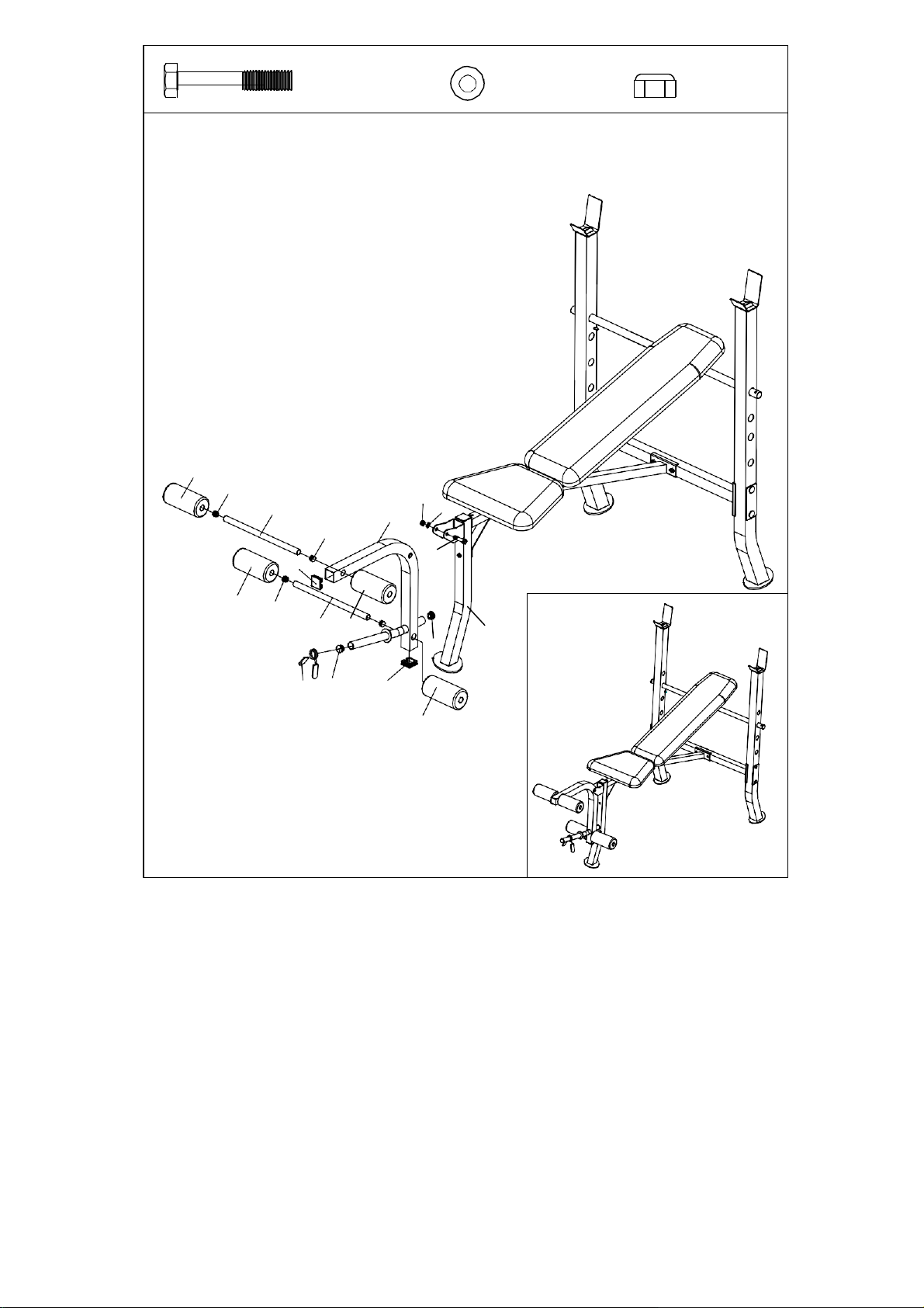
STEP 4:
Attach the Leg Developer (No. 9) to the Front Post (No. 5) using 1 Hex Bolt (No. 25), 1
Washer (No. 31), and 1 Aircraft Nut (No. 33). Tighten and secure with Spanner (No.
14).
Insert the Foam Roller Bars (No. 7) through the holes located on the Leg Developer
(No. 9). Next, attach the Foam Rollers (No. 17) onto each end of the Foam Roller Bars
(No. 7).
Lastly, slide the Spring Clip (No. 19) onto the bar located on the bottom of the Leg
Developer (No. 9).
The assembly is complete!
17
15
7
9
33
31
15
25
16
17
15
7 17
5
18
19
18
16
17
#33 (M10) (1pc)
#31 (3/4") (1pc)
#25 (M10x2 3/8") 1pc
10
OPERATION & ADJUSTMENTS
WEIGHT CAPACITY AND DIMENSION:
1. The maximum user weight on the bench is 250 lbs.
2. The maximum weight on the upright is 100 lbs.
3. The maximum weight capacity of the bench (including the user weight) is 350 lbs.
4. The maximum weight capacity of the leg developer is 50 lbs.
5. Assembled dimension: 57L x 46W x 32H
BENCH OPERATION:
1. The bench should be placed on a flat surface. For best stability and performance, the
incline or decline of the surface should be limited to 3% or less.
2. When removing the weight plates (not included), weight plates on the bar must be
taken off in equal amounts at the same time. This will prevent the bar from becoming
unevenly weighted, which will cause the bar to tip. It is strongly recommended that the
bar is removed from the upright and placed on the ground whenever adding or
removing weight plates.
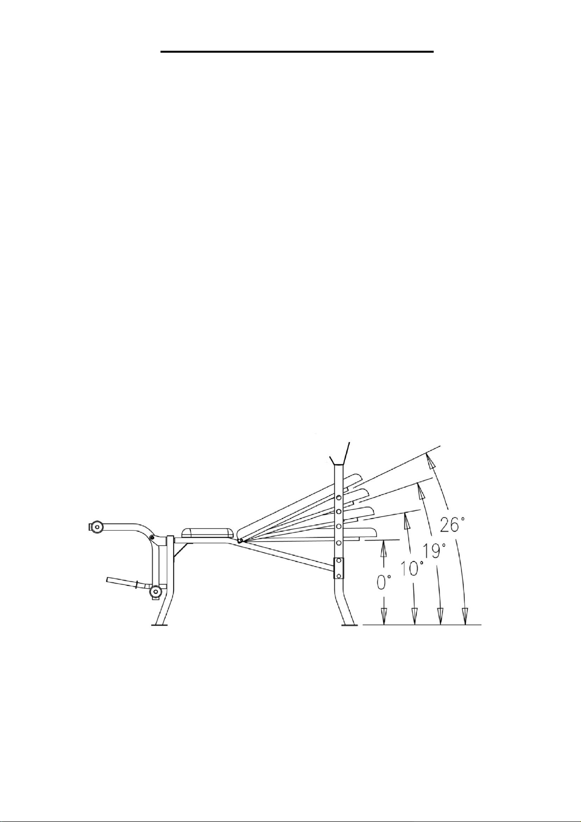
3. Use the Adjustable Backrest Bar (No. 6) to adjust the position of the Backrest
Board (No. 11). It can be adjusted in 4 different positions. When adjusting the
Backrest Board (No. 11) ensure that the Adjustable Backrest Bar (No. 6) is
securely placed in the support slot.

11
MAINTENANCE
IMPORTANT:
Safe and effective use can only be achieved if the equipment is assembled, maintained
and used properly. It is your responsibility to ensure that the equipment is maintained
regularly. Any components found to be worn and/or damaged should be replaced before
continuing use of the equipment. Equipment should only be used and stored indoors,
prolonged exposure to weathering and changes in temperature and humidity may have a
severe impact on the equipment.
Daily Maintenance:
- Clean and remove sweat and moisture after each use.
- Perform inspection of all nuts and bolts associated with moving parts of the equipment,
tighten as required.
- Check the mobility of moving parts and components on the equipment, lubricate if
required.
- Clean plastic parts of the equipment using a damp cloth, clean metal parts of the
equipment using a dry cloth. Do not use cleaning products to clean the equipment.
Weekly Maintenance:
- Thoroughly inspect the parts of the equipment; nuts, bolts, screws and moving parts
such as the slide collar, seat/back pad, support bar, etc. Tighten or replace parts as
required.
Monthly Maintenance:
- Inspect the frame and inner working components for wear and tear as well as damage,
maintenance or replace as required.
Version 1.2

12