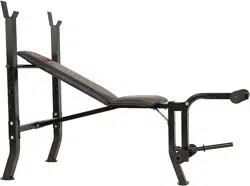
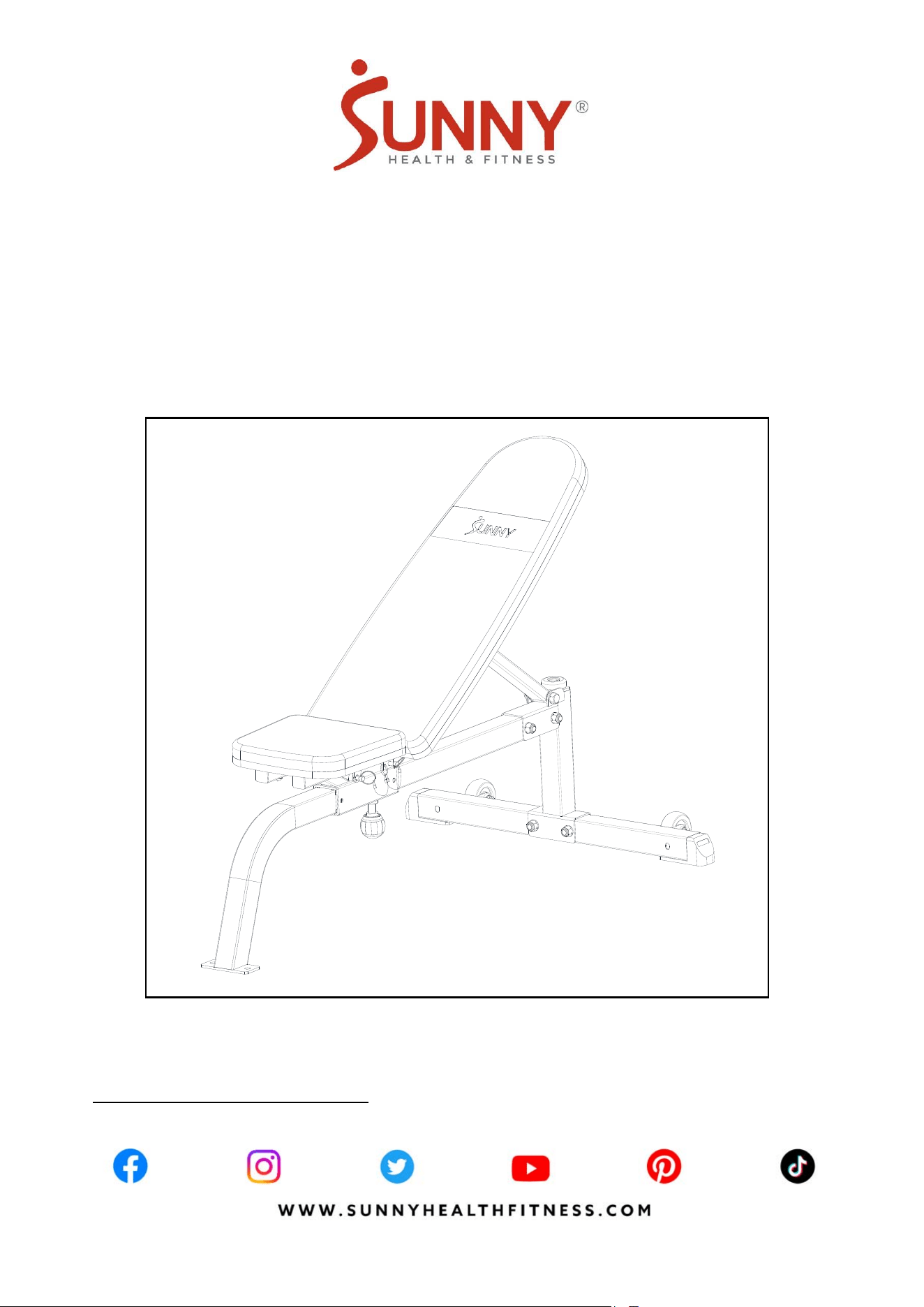
ADJUSTABLE MULTIFUNCTION
WEIGHT BENCH
SF-BH622045
USER MANUAL
IMPORTANT! Please retain owner’s manual for maintenance and adjustment instructions. Your
satisfaction is very important to us, PLEASE DO NOT RETURN UNTIL YOU HAVE CONTACTED
US: [email protected]m or 1-877-90SUNNY (877-907-8669).

1
IMPORTANT SAFETY INFORMATION
We thank you for choosing our product. To ensure your safety and health, please use this equipment
correctly. It is important to read this entire manual before assembling and using the equipment. Safe
and effective use can only be achieved if the equipment is assembled, maintained, and used
properly. It is your responsibility to ensure that all users of the equipment are informed of all warnings
and precautions.
1. Before starting any exercise program, you should consult your physician to determine if you have
any medical or physical conditions that could put your health and safety at risk or prevent you
from using the equipment properly. Your physician’s advice is essential if you are taking
medication that affects your heart rate, blood pressure, or cholesterol level.
2. Be aware of your body’s signals. Incorrect or excessive exercise can damage your health. Stop
exercising if you experience any of the following symptoms: pain, tightness in your chest,
irregular heartbeat, shortness of breath, lightheadedness, dizziness, or feelings of nausea. If you
do experience any of these conditions, you should consult your physician before continuing with
your exercise program.
3. Keep children and pets away from the equipment. The equipment is designed for adult use only.
4. Use the equipment on a solid, flat level surface with a protective cover for your floor or carpet.
To ensure safety, the equipment should have at least 2 ft (60 cm) of free space all around it.
5. Ensure that all nuts and bolts are securely tightened before using the equipment. The safety of
the equipment can only be maintained if it is regularly examined for damage and/or wear and
tear.
6. Always use the equipment as indicated. If you find any defective components while assembling
or checking the equipment, or if you hear any unusual noises coming from the equipment during
exercise, discontinue use of the equipment immediately and do not use until the problem has
been rectified.
7. Wear suitable clothing while using the equipment. Avoid wearing loose clothing that may become
entangled in the equipment.
8. Do not place fingers or objects into the moving parts of the equipment.
9. The maximum weight capacity (including user weight): 520lbs (235kgs).
10. The equipment is not suitable for therapeutic use.
11. To avoid bodily injury and/or damage to the product or property, proper lifting and moving are
required.
12. Your product is intended for use in cool and dry conditions. You should avoid storage in extreme
cold, hot or damp areas as this may lead to corrosion and other related problems.
13. This equipment is designed for indoor and home use only; it is not intended for commercial use.
2
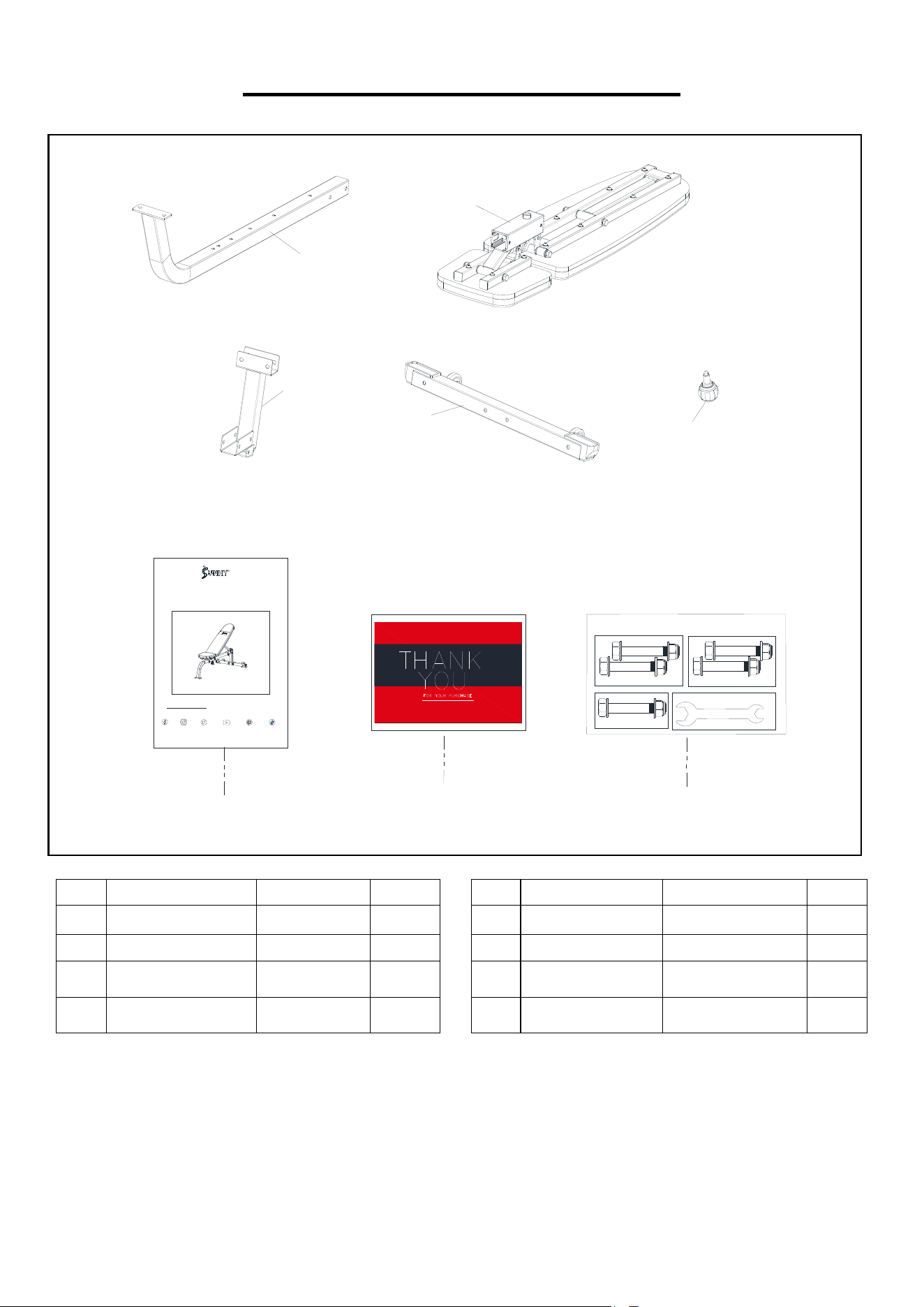
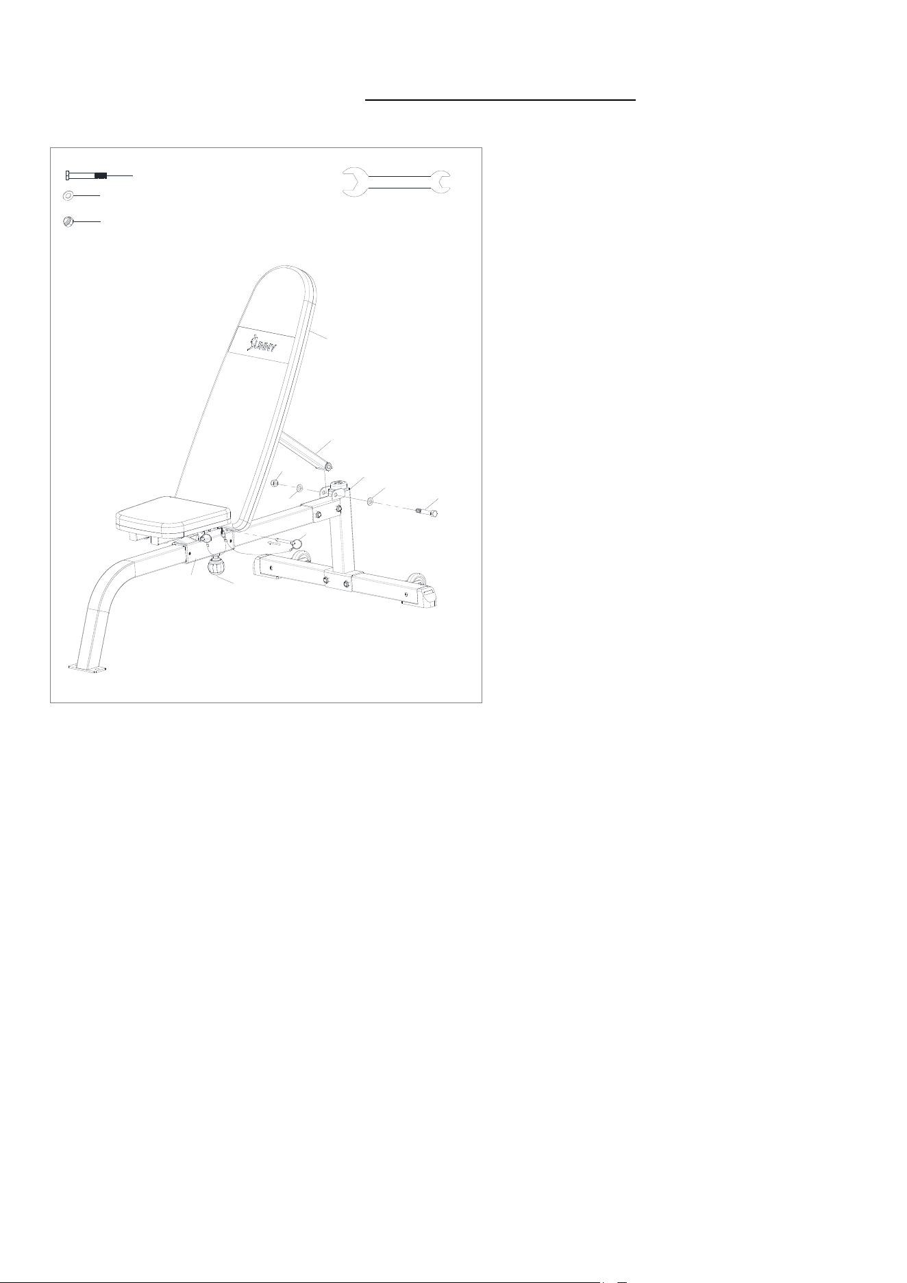
PRE-ASSEMBLY CHECK LIST
Before you start to assemble, please make sure all parts are included.
1
4
3
2
ADJUSTABLE MULTIFUNCTION
S
F-BH
6
22
0
4
5
USER MANUAL
IMP
O
RTAN T! Pl
ease
r
eta
in
o
wn
e
r’
s
m
a
n
ua
lf
o
rm
a
in
te
n
a
n
ce a
n
dad
j
ust
m
e
n
t
in
st
r
uct
i
o
n
s
.Y
ou
r
sat
i
s
f
act
i
o
ni
s
v
e
r
y
im
p
o
r
ta
n
ttous
,
PLEA
S
ED
O
N
O
TRET
U
RN
U
NTILY
OU
HAVE
CO
NTA
C
TED
US:su
pp
ort
@
sunn
y
healthfitness.com or 1- 877 - 90SUNNY
(
877-907-8669
)
.
A
B
C
HEALTH & FITNESS
WWW.SUNNYHEALTHFITNESS.COM
R
WEIGHT BENCH
#24-M12*75mm 2PCS
#25-
∮
24*
∮
12.5*2.0mm 4PCS
#26-M12 2PCS
STEP 2
#24-M12*75mm 1PC
#25-
∮
24*
∮
12.5*2.0mm 2PCS
#26-M12 1PC
STEP 5
#29 17-19 2PCS
#24-M12*75mm 2PCS
#25-
∮
24*
∮
12.5*2.0mm 4PCS
#26-M12 2PCS
STEP 3
SF-BH622045
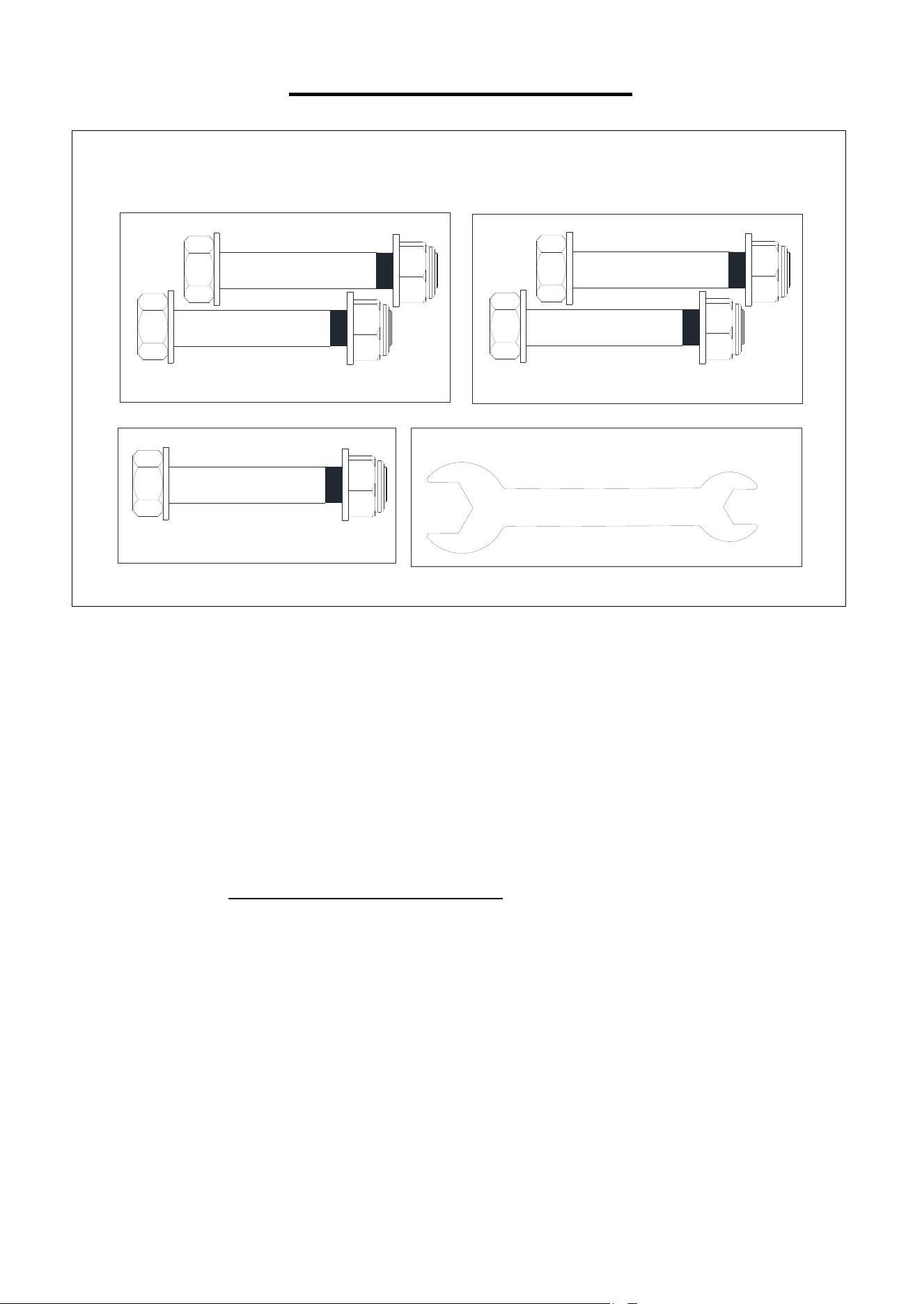
HARDWARE PACKAGE
13
No. Description Spec. Qty.
No. Description Spec. Qty.
1 Main Frame 1 13 Spring Knob M16*∮50 1
2 Stabilizer Tube 1 A Manual 1
3 Rear Support Tube 1 B Thank You Card 1
4
Adjustable Support
Frame
1 C
Hardware
Packa
g
e
1
3
HARDWARE PACKAGE
#24-M12*75mm 2PCS
#25-
∮
24*
∮
12.5*2.0mm 4PCS
#26-M12 2PCS
STEP 2
#24-M12*75mm 1PC
#25-
∮
24*
∮
12.5*2.0mm 2PCS
#26-M12 1PC
STEP 5
#29-17-19 2PCS
#24-M12*75mm 2PCS
#25-
∮
24*
∮
12.5*2.0mm 4PCS
#26-M12 2PCS
STEP 3
SF-BH622045
HARDWARE PACKAGE
Ordering Replacement Parts (U.S. and Canadian Customers only)
Please provide the following information in order for us to accurately identify the part(s) needed:
The model number (found on cover of manual)
The product name (found on cover of manual)
The part number found on the “EXPLODED DIAGRAM” (page 9) and “PARTS LIST” (page 10)
Please contact us at support@sunnyhealthfitness.com or 1-877-90SUNNY (877-907-8669).
4
ASSEMBLY INSTRUCTIONS
We value your experience using Sunny Health and Fitness products. For assistance with parts or
troubleshooting, please contact us at support@sunnyhealthfitness.com or 1-877-90SUNNY (877-
907-8669).
1
4
#24-M12*75mm 2PCS
#25-
∮24*∮12.5*2.0mm 4PCS
#26-M12 2PCS
#29-#17-19 2PCS
1
3
24
24
25
25
25
25
26
26
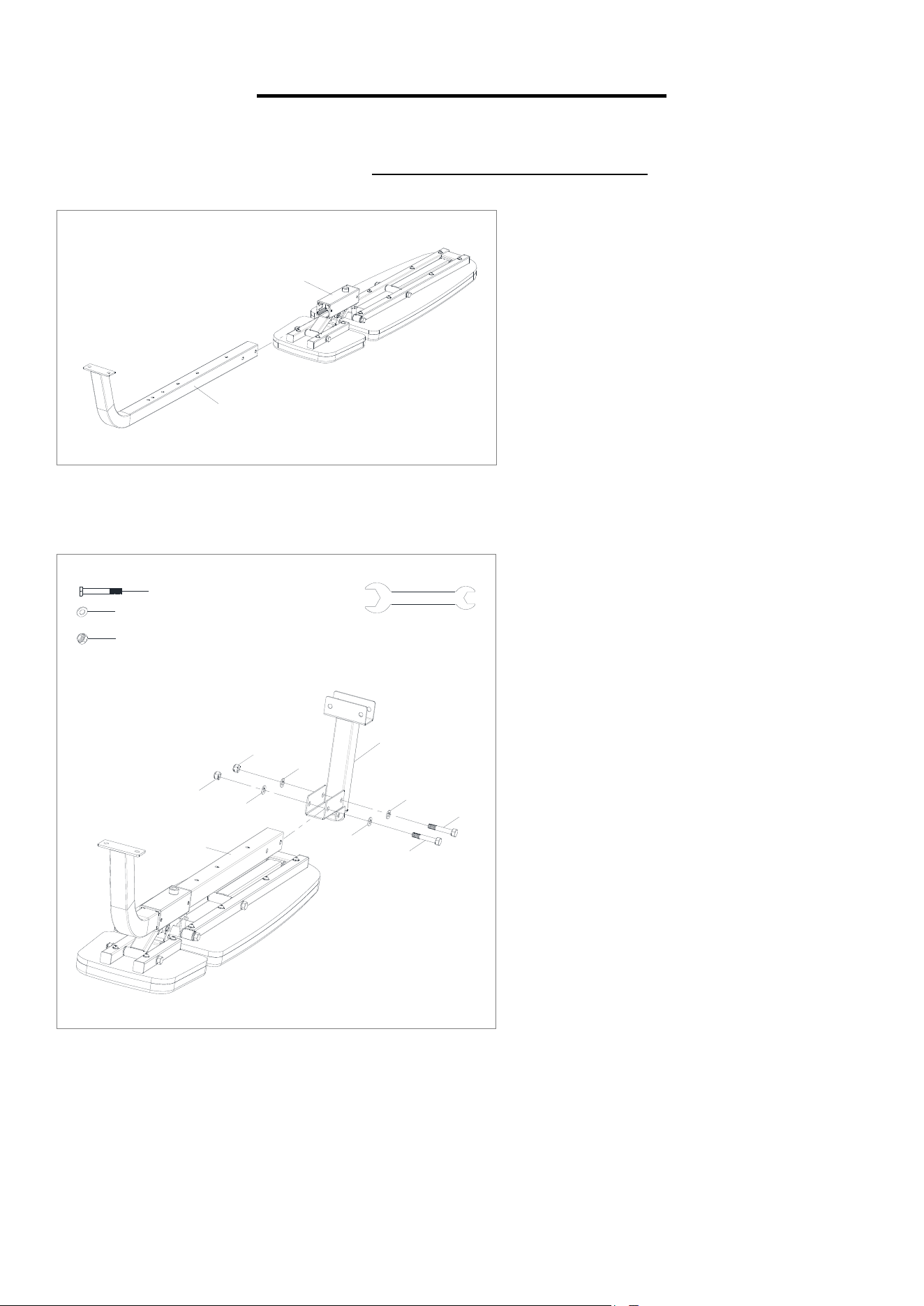
STEP 1:
Attach the Main Frame (No. 1) to the
assembled Adjustable Support Frame
(No. 4).
STEP 2:
Attach the Rear Support Tube (No. 3) to
the assembled Main Frame (No. 1) using
2 Hex Bolts (No. 24), 4 Flat Washers
(No. 25) and 2 Nylon Nuts (No. 26).
Tighten and secure with 2 Wrenches
(No. 29).
5
We value your experience using Sunny Health and Fitness products. For assistance with parts or
troubleshooting, please contact us at support@sunnyhealthfitness.com or 1-877-90SUNNY (877-
907-8669).
#24-M12*75mm 2PCS
#25-
∮24*∮12.5*2.0mm 4PCS
#26-M12 2PCS
#29-#17-19 2PCS
3
2
24
24
25
25
25
25
26
26
#13-M16*∮50 1PC
14
13
4
16
1
2
3
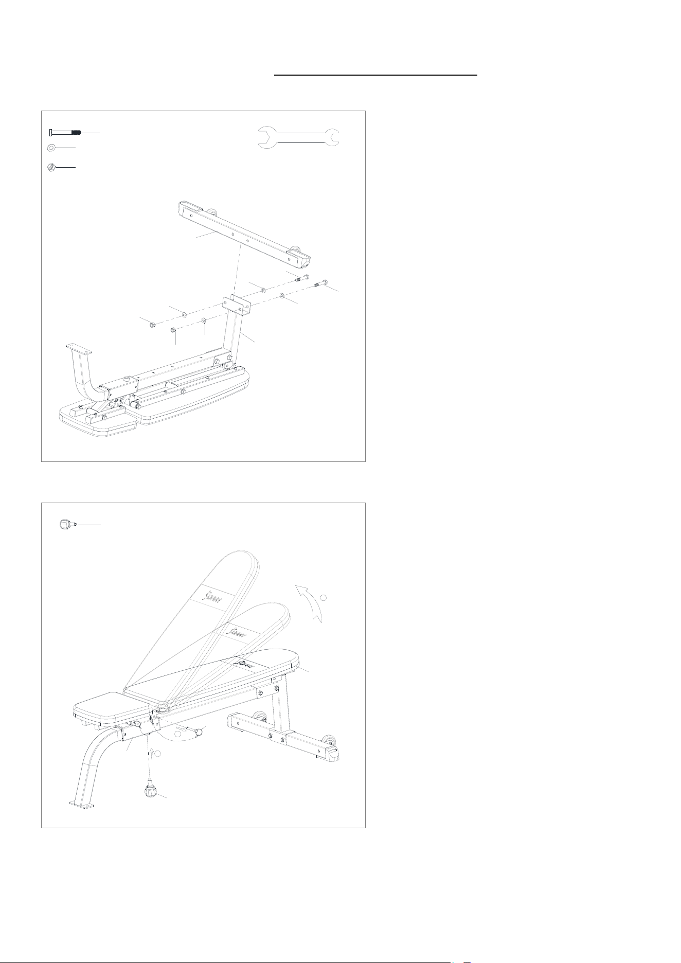
STEP 3:
Attach the Stabilizer Tube (No. 2) to the
Rear Support Tube (No. 3) using 2 Hex
Bolts (No. 24), 4 Flat Washers (No. 25)
and 2 Nylon Nuts (No. 26). Tighten and
secure with 2 Wrenches (No. 29).
STEP 4:
Pull out the Pin (No. 16) and lift the
Backrest (No. 14) to proper position,
insert the Spring Knob (No. 13) to
secure.
6
We value your experience using Sunny Health and Fitness products. For assistance with parts or
troubleshooting, please contact us at support@sunnyhealthfitness.com or 1-877-90SUNNY (877-
907-8669).
#24-M12*75mm 1PC
#25-
∮24*∮12.5*2.0mm 2PCS
#26-M12 1PC
#29-#17-19 2PCS
4
16
24
25
25
26
7
3
13
14
STEP 5:
Attach Rear Adjustable Tube (No. 7) to
the Rear Support Tube (No. 3) by using
1 Hex Bolt (No. 24), 2 Flat Washers (No.
25) and 1 Nylon Nut (No. 26). Secure
with 2 Wrenches (No. 29) but do not
secure too tight.
Loosen and pull out the Spring Knob
(No. 13) to adjust the Backrest (No. 14)
to desired angle, then re-insert and
tighten the Spring Knob (No. 13) and re-
insert Pin (No. 16) to secure.
The assembly is complete!
7
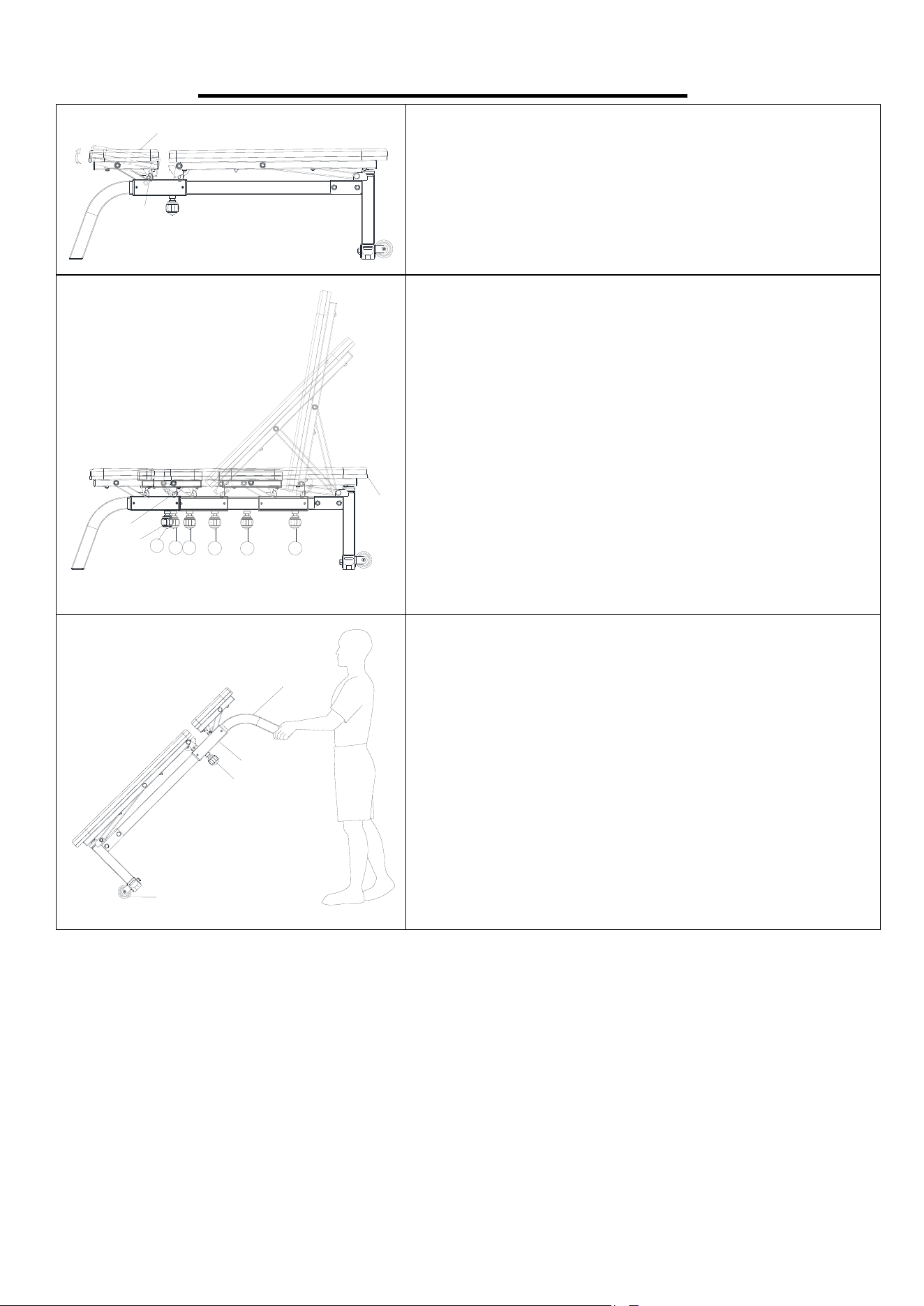
ADJUSTMENTS & USAGE GUIDE
16
15
ADJUSTING THE SEAT ANGLE
The seat of bench has 2 different angle settings. To
adjust the angle of the seat, pull out the Pin (No. 16)
and lift the Seat (No. 15), then re-insert the Pin (No. 16)
to secure.
13
14
1
2
3
4
5
6
16
ADJUSTING THE BACKREST ANGLE
There are 6 different adjustments for backrest. To adjust
the backrest angle, pull out the Pin (No. 16), then loosen
and pull out Spring Knob (No. 13), push the Backrest
(No. 14) back to desired height, then re-insert and
tighten the Spring Knob (No. 13) and re-insert Pin (No.
16) to secure.
CAUTION!
To avoid any injury, please make sure that the Spring
Knob (No. 13) is properly engaged. Once the Spring
Knob (No. 13) is tightened, the height can’t be adjusted.
9
1
4
13
MOVING THE BENCH
Before moving, please make sure the Main Frame (No.
1) is tightened to the Adjustable Support Frame (No.
4) with Spring Knob (No. 13).
To move the bench, lift the end of the Main Frame (No.
1) until the Transportation Wheels (No. 9) touch the
ground. With the Transportation Wheels (No. 9) on the
ground, you can transport the bench to the desired
location with ease.

8
MAINTENANCE INSTRUCTIONS
DAILY MAINTENANCE
Inspect and tighten all parts regularly. (Nuts, Bolts, Rubber Pads, Steel Brackets, etc.)
Replace any worn or torn parts immediately.
Check and ensure the equipment is levelled at all time.
Check and tighten all adjustment pins/knobs regularly.
WEEKLY MAINTENANCE
Use damp cloth on plastic parts only, use dry cloth on metal frames.
Inspect the metal frame structure of the equipment.
9
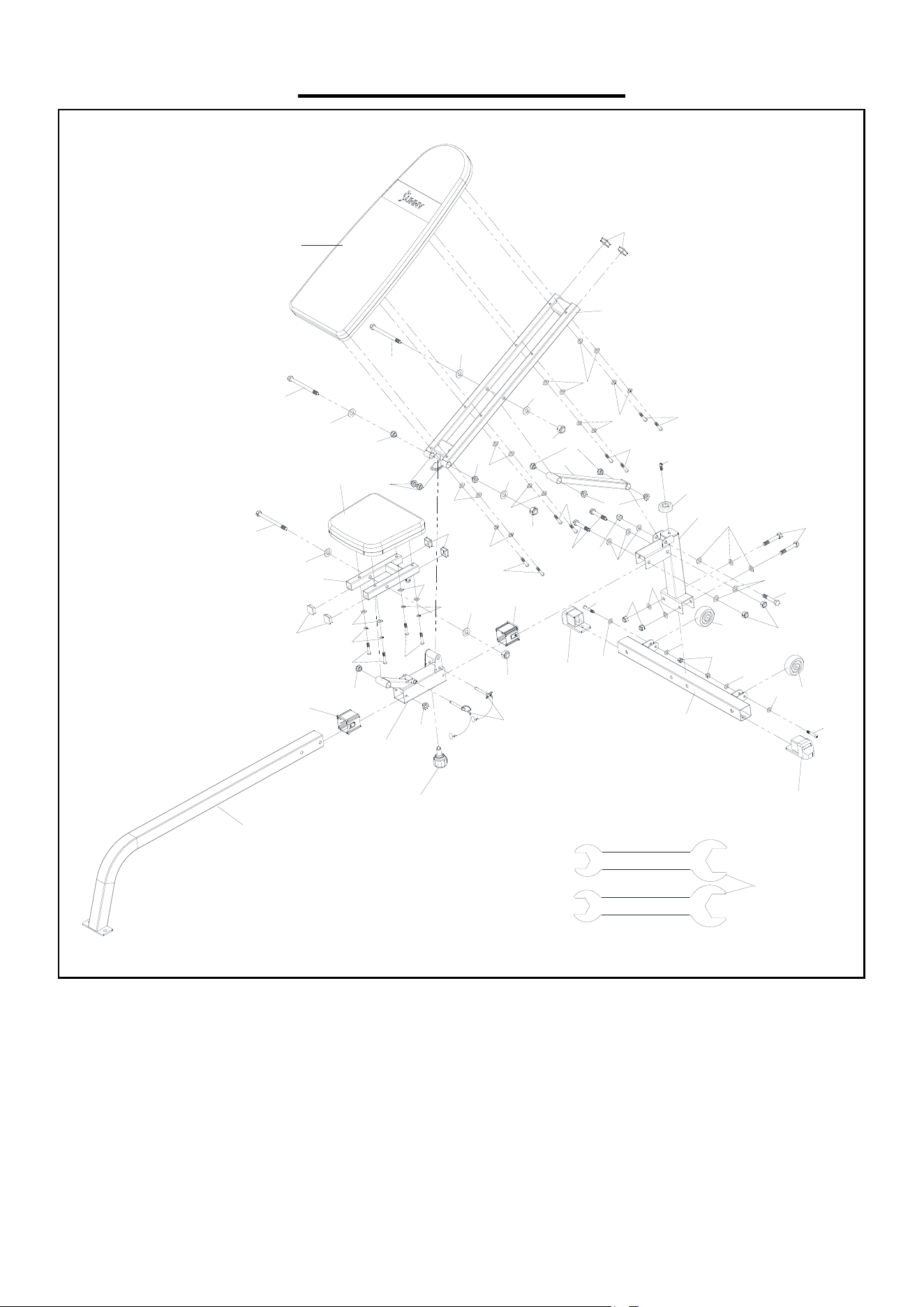
EXPLODED DIAGRAM
1
2
3
4
5
6
7
8
8
9
9
10
11
12
12
12
15
14
13
16
17
17
17
17
17
17
17
18
18
18
18
18
18
19
19
19
19
19
20
20
20
20
20
21
21
20
20
23
20
20
22
24
25
26
25
24
26
24
25
25
25
25
25
25
25
25
26
26
26
26
28
27
28
29
10

10
PARTS LIST
No. Description Spec. Qty.
No. Description Spec. Qty.
1 Main Frame 1 16 Pin ∮10*90 2
2 Stabilizer Tube 1 17 Alloy Wrap 10
3 Rear Support Tube 1 18
Hex Socket Head
Bolt
M8*50mm 12
4
Adjustable Support
Frame
1 19 Spring Washer M8 12
5 Seat Support Tube 1 20 Flat Washer ∮16*∮8.5*1.5 16
6
Backrest Support
Tube
1 21
Hex Socket Head
Bolt
M8*45mm 2
7
Rear Adjustable
Tube
1 22 Nylon Nut M8 2
8 Foot End Cap 50*50*1.5 2 23
Hex Socket Head
Bolt
M8*23mm 1
9
Transportation
Wheel
2 24 Hex Bolt M12*75mm 5
10 Plastic Bushing 2 25 Flat Washer ∮24*∮12.5*2.0mm 16
11 Buffer 1 26 Nylon Nut M12 8
12 Square End Cap 30*30*1.5 6 27 Hex Bolt M12*150mm 1
13 Spring Knob M16*∮50 1 28 Hex Bolt M12*145mm 2
14 Backrest 1 29 Wrench #17-19 2
15 Seat 1
Version 1.1

11