
Loading ...
Loading ...
Loading ...
ECO control operation
4EMPERATURESETTINGS — You must ensure that the
ECO control is set for the proper water temperatures
for the system. Excessive water temperature can cause
significant property damage in some applications.
-ULTITEMPERATURESYSTEMS — If the heating system
includes circuits that require lower temperature water
(radiant slab circuits, for example) as well as higher
temperature circuits (DHW, finned tube baseboard,
etc.), it is recommended to protect low-temperature
circuits with limit controls that are wired to a ECO
control external limit circuit. Failure to provide regula-
tion can result in substantial property damage.
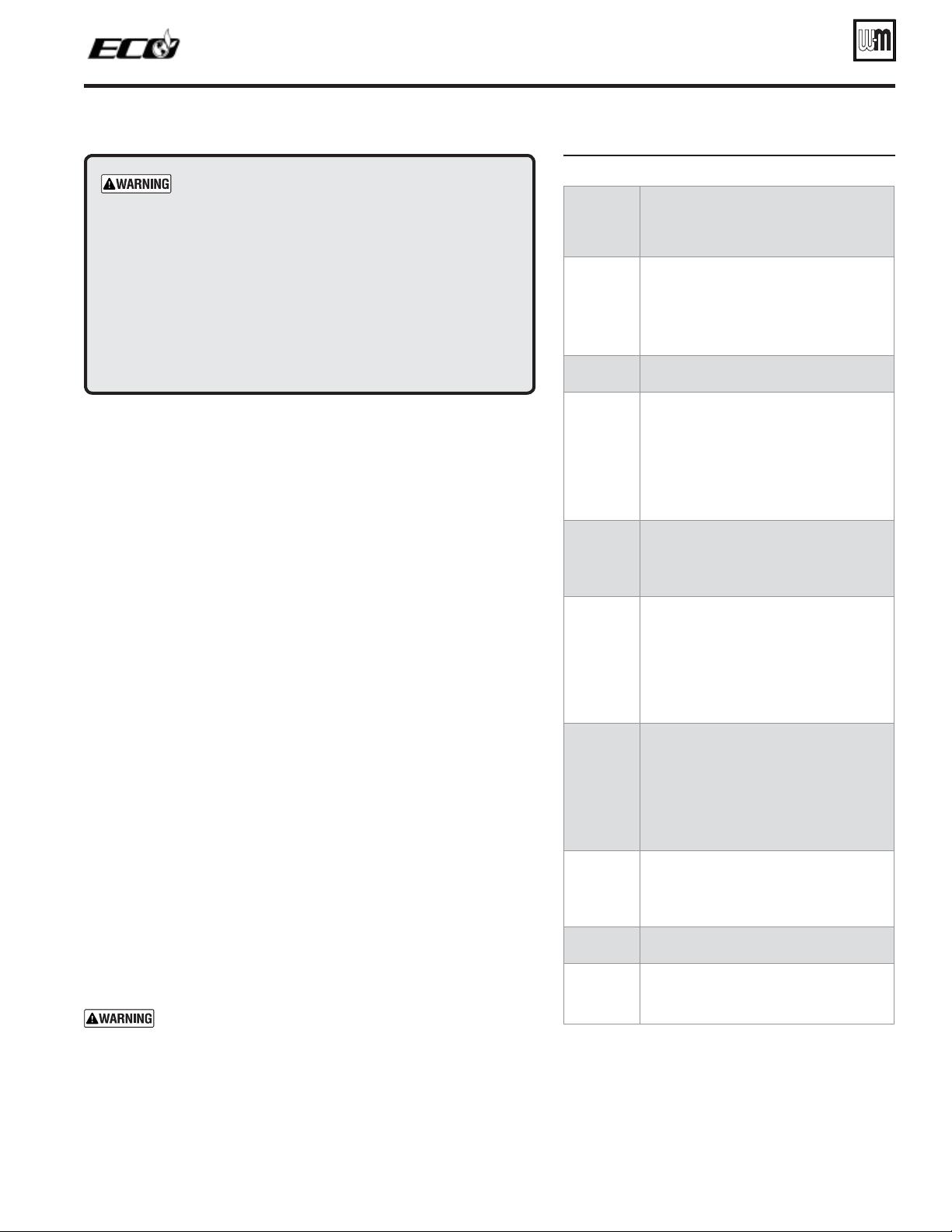
&IGURE Control sequence of operation
$ISPLAY
status
TEXT
#ONTROLACTION
(also see Figure 70, page 64)
0/7%2
50
s Check the boiler model listed on the power-up
screen. If it is not correct, turn off the boiler. See
page 67 to change setting.
s When power is turned on, the screen lists sen-
sors that are detected. If any sensor is not listed,
make sure it is connected correctly. Turn off
power and restart.
3TANDBY
s Standby — no calls for heat.
s Backlight will turn off due inactivity.
0REPURGE
s Call for heat detected.
s Display on with BLUE light (HEAT) or PURPLE
light (DHW).
s Start min./max. on timers if more than one
system is calling — highest priority starts first.
s Start circulators for this priority setup.
s Calculate target temp — If sensor temp is below
target temp, begin firing sequence.
s Blower to ignition speed for prepurge.
)GNITION
s After prepurge times out, begin ignition cycle
s Activate gas valve and ignition spark.
s Continue ignition spark for ignition period
s Turn off spark and use electrode to check for
flame signal.
(%!4).'
s Flame detected.
s Release boiler to modulation.
s NOTE: If flame is not detected, the gas valve
is turned off, blower turns on (postpurge), and
control starts cycle again. After 5 failures, the
control waits 60 minutes, then tries again.
s If priority timer times out, switch to next priority
and start priority timer.
s If demand satisfied, go to postpurge.
$(7
s Flame detected.
s Release boiler to modulation.
s NOTE: If flame is not detected, the gas valve
is turned off, blower turns on (postpurge), and
control starts cycle again. After 5 failures, the
control waits 60 minutes, then tries again.
s If priority timer times out, switch to next priority
and start priority timer.
s If demand satisfied, go to postpurge.
0OSTPURGE
s Demand satisfied (temperature reaches target
temperature or limit setting).
s Gas valve off.
s Blower to ignition speed for postpurge.
s Return to standby after purge.
%RRORFAULT
s Display turns RED due to error or limit event.
s Flashing display means lockout condition.
773$
s Warm weather shutdown — the boiler will not
be allowed to fire on space heating if the outside
temperature is greater than the WWSD setting.
DHW operation is not affected by WWSD.
Part number 550-142-122/0513
63
TM
GAS-FIRED WATER BOILER — Boiler Manual
Control features
❏
Blower speed modulation to control the ECO boiler’s firing rate.
❏
Advanced PID response to anticipate system needs based on response
to heat input.
❏
Robust text display for ease of operation monitoring and troubleshoot-
ing.
❏
Control of two dedicated inputs for DHW and HEAT respectively.
❏
Integral outdoor reset option (see page 119).
❏
Dual sensors for boiler outlet temperature and flue temperature, pro-
viding redundant protection.
❏
Low water cut-off, (field wired or optional kit).
❏
Boiler is shipped with an outdoor sensor, allowing outdoor reset opera-
tion for maximum boiler efficiency. See page 119.
❏
Freeze protection and circulator exercising.
Sequence of operation
1. Figure 69 is a summary of the operating sequence for the ECO control.
❏
The statuses shown appear in the display as the ECO control cycles
the boiler.
❏
The display will flash red if a problem has been detected.
ECO control setup
"%&/2%02/#%%$).'PERFORM%33%.4)!,CONTROL
SETTINGSASINSTRUCTEDONPAGE.
1. See Figure 71, page 66 for an overview of the ECO control menus.
This page also gives the location of instruction manual information
for each of the main menus.
Loading ...
Loading ...
Loading ...