
Loading ...
Loading ...
Loading ...
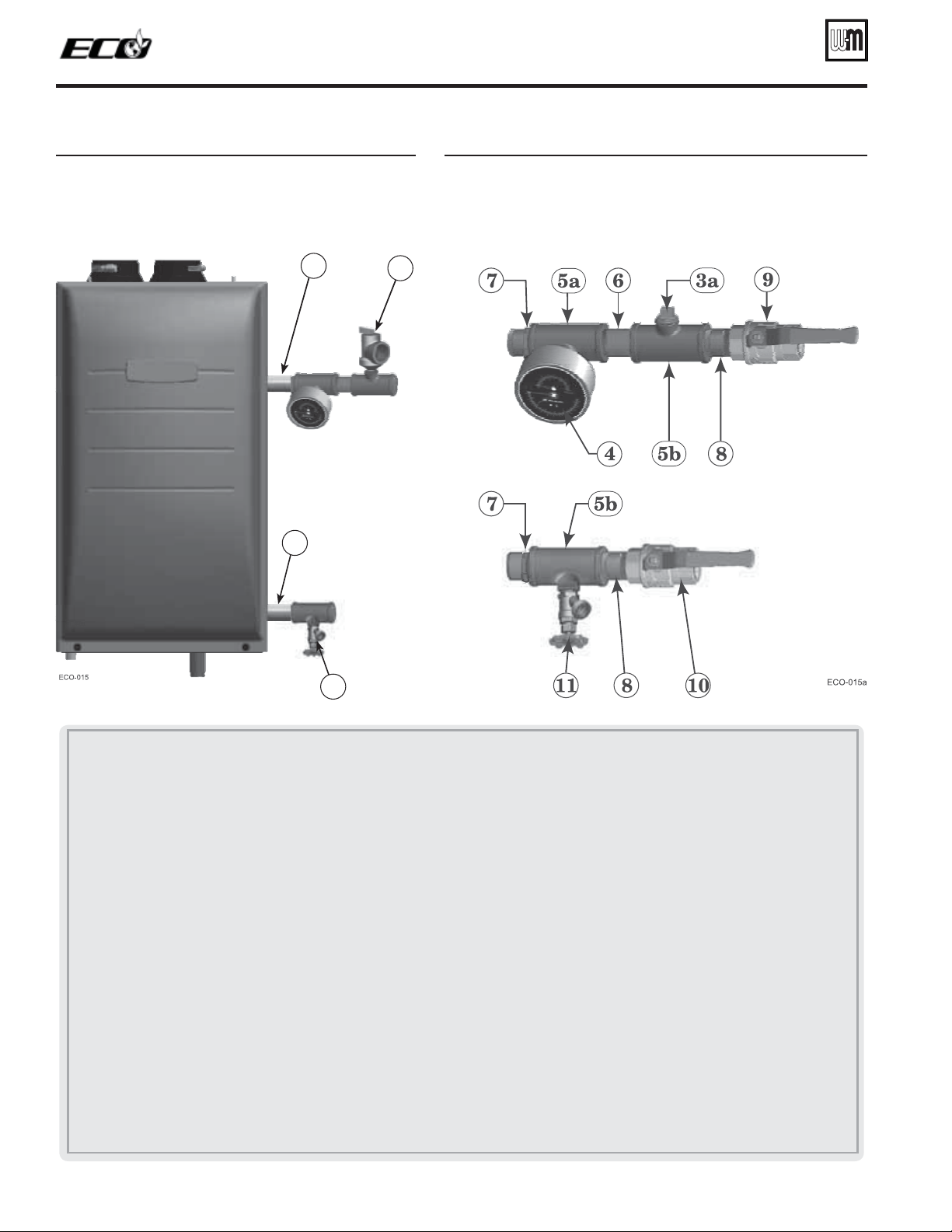
&IGURE Install pipe fittings for relief valve and
pressure/temperature gauge —
$/
./4MOUNTRELIEFVALVEUNTIL!&4%2
HYDROSTATICTESTING
(see legend below)
&IGURE Install piping components required for hydrostatic
test (
see legend below)
3
1
Part number 550-142-122/0513
12
TM
GAS-FIRED WATER BOILER — Boiler Manual
1 Boiler supply (outlet) connection, (male, 1” NPT )
2 Boiler return (intlet) connection, (male, 1” NPT )
3 Boiler relief valve, shipped loose with boiler — $/./4MOUNTRELIEFVALVEUNTIL!&4%2HYDROSTATICTESTING.
3a 4%-0/2!2),9/.,9 Insert a ¾” NPT plug in the relief valve tapping of the reducing tee. 4HIS-534"%2%-/6%$AFTER
THETESTANDTHERELIEFVALVEMOUNTEDHERE.
4 Pressure/temperature gauge, shipped loose with boiler
5a Reducing tee, NPT, 1 ” x 1 ” x ¼” on 70/110, & 1 ¼” x 1 ¼” x ¼” on 155, shipped loose with boiler
5b Reducing tee, NPT, 1 ” x 1 ” x ¾” on 70/110, & 1 ¼” x 1 ¼” x ¾” on 155, shipped loose with boiler
6 Nipple, NPT 1” x close on 70/110, & 1 ¼” x close on 155, shipped loose with boiler
7 Reducing bushing, NPT, 1 ¼” x 1”, shipped loose with boiler (155 only)
8 Nipple, NPT 1” x close on 70/110, & 1 ¼” x close on 155, by installer
9 Isolation valve on supply connection, by installer (1” NPT on 70/110, 1¼” NPT on 155)
10 isolation valve on return connection, by installer (1” NPT on 70/110, 1¼” NPT on 155)
11 ¾” NPT boiler drain valve, shipped loose with boiler — after hydrostatic testing, move drain valve to lowest point on the return piping if not
already there.
Boiler hydrostatic test (continued)
(155 only)
(155 only)
11
Piping from system
Piping to system
2
Loading ...
Loading ...
Loading ...