Loading ...
Loading ...
Loading ...
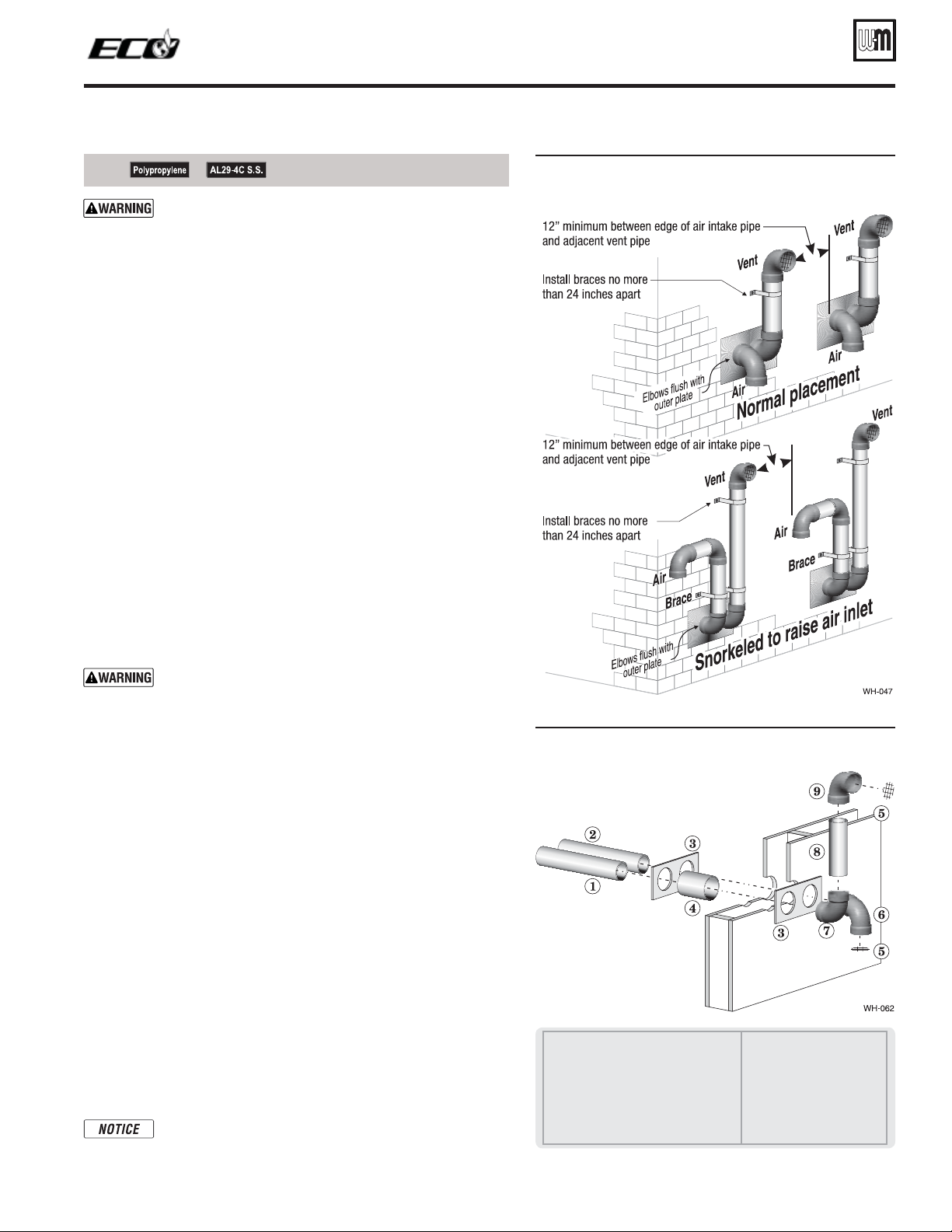
DIRECT VENT — 3IDEWALLWITHSEPARATEPIPES (continued)
All vent pipes and air inlets must terminate at the same
height to avoid possibility of severe personal injury, death
or substantial property damage.
2. Place wall penetrations to obtain minimum clearances shown in
Figure 24 for U. S. installations. For Canadian installations, provide
clearances required by CSA B149.1 or B149.2 Installation Code and
a ULC S636 compliant vent kit.
3. The air inlet of a ECO boiler is part of a direct vent connection. It
is not classified as a forced air intake with regard to spacing from
adjacent boiler vents.
0REPAREWALLPENETRATIONS
1. Air pipe penetration:
a. Cut a hole for the air pipe. Size the air pipe hole as close as
desired to the air pipe outside diameter.
2. Vent pipe penetration:
a. Cut a hole for the vent pipe. For either combustible or non-
combustible construction, size the vent pipe hole at least 0.4”
larger than the vent pipe diameter.
b. Insert a galvanized metal thimble in the vent pipe hole as
shown in Figure 25.
3. Use the provided paper template for correct location of hole centers.
4. Use of a sidewall termination plate is REQUIRED.
a. Kits for several vent sizes are available from Weil-McLain.
See “VENT/AIR PARTS AND KITS” on page 107.
b. Plate may be field fabricated from corrosion resistant material
of sufficient strength. Plate must allow venting to maintain
minimum clearance to combustibles.
Ensure that the plate material is strong enough to prevent
the termination from being pushed inward if struck or
pushed from the outside.
5. Follow all local codes for isolation of vent pipe when passing
through floors or walls.
6. Seal exterior openings thoroughly with exterior caulk.
4ERMINATIONANDlTTINGS
1. Prepare the vent termination elbow and the air termination elbow
by inserting bird screens. (See Figure 23, page 24.) Bird screens
must be purchased separately. See the parts list at the end of this
manual for part numbers.
2. Secure the elbows so they will butt against the sidewall termina-
tion plate.
3. When completed, the air termination coupling must be oriented
at least 12 inches below the vent termination and at least 12 inches
above grade or snow line as shown in Figure 23, page 24.
4. You can orient the vent termination elbow either directly out-
ward or 90 degrees away from the air inlet elbow as shown in
Figure 23, page 24.
5. Maintain the required dimensions of the finished termination
piping as shown in Figure 23, page 24.
6. For multiple boiler terminations, see Figure 24.
7. Do not extend exposed vent pipe outside of building more than
shown in this document. Condensate could freeze and block vent
pipe.
If extending the vent and air pipes out from the wall,
install a coupling on each pipe. Mount the piping with
the coupling flush with the outer plate.
&IGURE
Multiple separate pipes sidewall terminations
— maintain vertical spacing between vent and
air fittings shown in Figure 23, page 24
&IGURE Sidewall termination assembly — using
separate pipes
1 Vent piping
2 Air piping
3 Sidewall termination plates: for 3” PVC,
use plates supplied with boiler in W-M
vent/air plate kit; for 3” AL29-4C or 2” PVC,
purchase optional sidewall separate pipes
plate kit
4 Galvanized thimbles, by in-
staller
5 Bird screen, by installer
6 Air inlet elbow
7 Elbow
8 Nipple
9 Elbow (vent termination)
See notices on previous page.
Part number 550-142-122/0513
25
TM
GAS-FIRED WATER BOILER — Boiler Manual
Loading ...
Loading ...
Loading ...