Loading ...
Loading ...
Loading ...
Field wiring
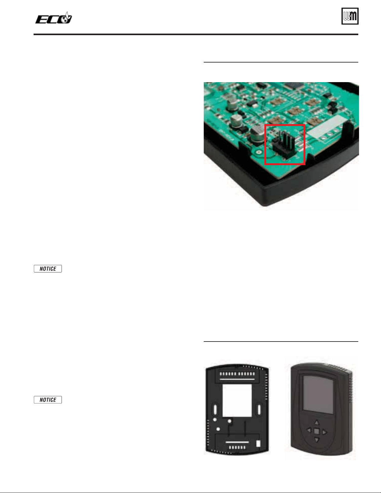
&IGURE Back of display circuit board -
4-pin terminal
Part number 550-142-122/0513
57
TM
GAS-FIRED WATER BOILER — Boiler Manual
Low voltage:
1. Mount multi-hole cord grip (provided) to desired low voltage
knockout and secure with a locknut.
2. Thermostat, aquastat, limit devices, and outdoor temperature
sensor wire pairs should be routed through the cord grip.
1. If routed through the bottom left knockouts, wires should
be connected directly into the corresponding terminal block.
2. If routed through the top right knockouts, wires should be
bundled together along the right side wire chase. Install a
wire tie base on each of the two bent tabs along the right side
to allow attachment of the provided wire ties.
3. Low water cutoff (optional) should be routed following the
instructions in step 3 or 4 above depending on entrance loca-
tion. Provide strain relief and a seal at cabinet entry.
4. Bundle all wires together with provided wire ties
5. After wires are attached to the control terminal blocks, hand-
tighten the nut of the cord grip to seal any unused holes and
grip wire tightly.
#ONNECTINGTHEDISPLAYWIREHARNESS
1. The display wire harness (shipped loose with boiler) is a long,
grey wire with a 4-pin connector on each end.
2. Remove the grommet from the hole in the right side of the boiler
jacket show in Figure 6, page 10. Route the harness through the
hole so that the push-in strain relief clips are inside the cabinet
and the grommet attached to the cable is outside the cabinet.
3. Connect the 4-pin connector on the inside of the boiler jacket
to pin P9 on the control.
Do not force the connector on to the pin. Connector
should only connect one way. If connector does not
easily slide on the pin, ensure connector is oriented
properly. If connector is forced or connected im-
properly, damage to the circuit board could result.
4. Push the strain relief clips into the extra holes provided on
the two bent tabs along the right side of the boiler. You may
need to push the wire harness or other low voltage wires out
of the way to access the holes.
5. Find the grommet that is attached to the display wire harness. In-
sert the grommet into the hole on the right side of the boiler cabi-
net. Ensure grommet seals around both the cabinet and the wire.
6. If using a junction box, install a wire clamp or strain relief to
one of the knockouts.
7. Unsnap the back plastic cover from the display housing.
Mount back plastic cover to the display bracket, wall or junc-
tion box depending on installation. Screws for mounting to
the display bracket are provided.
Ensure that the small, square hole in the corner of
the back plastic is located in the bottom right corner
when mounted. This provides room to connect the
display harness, see view at right).
8. Route wire depending on display location:
a. Display bracket—bundle wire behind the display bracket
and use a provided wire tie to neatly collect the extra wire
length. Leave enough wire to reach through bottom right
hole in the back plastic cover.
Proper orientation of display when mounted
b. Drywall or plaster—fish the wire through the wall or
through scoring in drywall and through the large, square
hole in the back of the display backing. Ensure wire does
not fall back into wall.
c. Junction box—route wire through the previously in-
stalled clamp or strain relief. Gather extra wire length
inside the box and tighten clamp to provide strain relief.
Route wire through the large square hole in the back
plastic cover.
9. Turn over the front half of the display so that the circuit
board is visible. Connect the 4-pin connector of the wiring
harness to the 4-pin terminal shown in Figure 63.
10. Fit the front display plastic to the back display plastic. Clip
the two halves together and ensure they are firmly secure.
The buttons should be located below the display screen (see
view below).
Loading ...
Loading ...
Loading ...