Loading ...
Loading ...
Loading ...
4
!
CAUTION
Select Location
The proper location will ensure peak performance of your
appliance. We recommend a location where the unit will
be out of direct sunlight and away from heat sources. To
-
mended installation location temperature range is from 50
to 100°F (10 to 38°C).
Cabinet Clearance
Ventilation is required from the bottom front of the appli-
ance. Keep this area open and clear of any obstructions.
Adjacent cabinets and counter top can be installed around
the appliance as long as the front grille remains unobstruct-
ed. All Marvel Professional models with articulated hinges
are intended for built-in applications only.
Front Grille
Do not obstruct the front grille. The openings within the
-
energy usage and loss of cooling capacity. For this reason
it is important this area to not be obstructed and the grille
openings kept clean. Marvel does not recommend the use
INSTALLING YOUR APPLIANCE
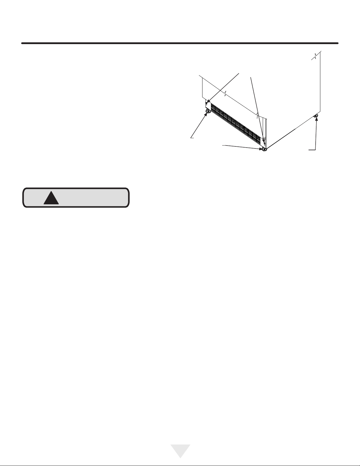
Figure 2
Front Leveling
Legs
Front grille
screws
Leveling Legs
Adjustable legs at the front and rear corners of the appli-
-
all height of your Marvel appliance may be adjusted higher
(by turning the leveling leg out, CCW) and lower (by turning
the leveling leg in, CW).
To adjust the leveling legs, place the appliance on a solid
lean the appliance back to access the front leveling legs.
Raise or lower the legs to the required dimension by turning
the legs. Repeat this process for the rear by tilting the appli-
ance forward using caution. On a level surface check the
appliance for levelness and adjust accordingly.
The front grille screws may be loosened and the grille ad-
justed to the desired height. When adjustment is complete
tighten the two front grille screws. (See Figure 2).
Rear
Leveling
Legs
Loading ...
Loading ...
Loading ...