Loading ...
Loading ...
Loading ...
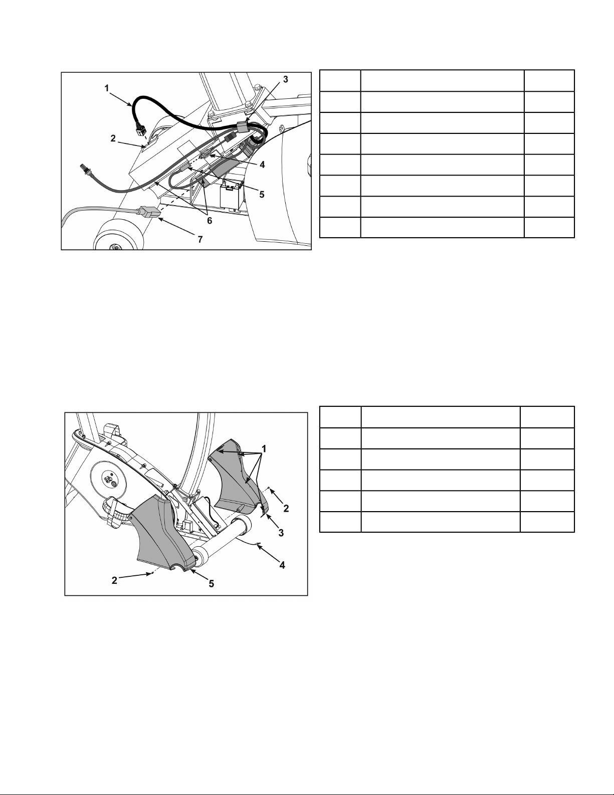
6. Route cables through gray clip on controller.
Qty.Description
1Display cable1
1Display cable connector2
1Gray clip3
1Power supply output4
1Console cable DIN connector5
1A/V cables, optional6
1Power cord7
7. Plug the display cable into the display cable connector on the lower control board.
Ensure the cable connector is securely fastened.
8. Connect the console cable’s DIN connector to the power supply output.
Make sure the two connectors snap firmly together and can not be pulled apart without pulling the
sleeve back to release it.
Install front covers
1. Install front left cover with one screw using a Phillips screwdriver.
Qty.Description
1Plastic Connectors1
1Screw2
1Front Left Cover3
1Optional A/V Cables4
1Front Right Cover5
2. Route optional A/V cables through front covers to front of unit.
Do not pinch or damage the cables during assembly.
In addition to the mounting screws, there are four plastic connectors that secure the front covers
together. Ensure that all four plastic connectors are inserted properly in each front cover.
3. Install front right cover with one screw using a Phillips screwdriver.
Page 18 of 80
Cybex 625C/625R Cycle Part Number LT-23688-4 F
Loading ...
Loading ...
Loading ...