
MODEL W1668/W1848
13
1
⁄4" OSCILLATING
DRILL PRESS
Phone: (360) 734-3482 • Online Technical Support: [email protected]
COPYRIGHT © MARCH, 2017 BY WOODSTOCK INTERNATIONAL, INC.
WARNING: NO PORTION OF THIS MANUAL MAY BE REPRODUCED IN ANY SHAPE OR FORM WITHOUT
THE WRITTEN APPROVAL OF WOODSTOCK INTERNATIONAL, INC.
Printed in China
#18837MN V2.03.17
OWNER'S MANUAL
(FOR MODELS MANUFACTURED SINCE 08/16)
W1848
W1668

This manual provides critical safety instructions on the proper setup,
operation, maintenance, and service of this machine/tool. Save this
document, refer to it often, and use it to instruct other operators.
Failure to read, understand and follow the instructions in this manual
may result in fire or serious personal injury—including amputation,
electrocution, or death.
The owner of this machine/tool is solely responsible for its safe use.
This responsibility includes but is not limited to proper installation in
a safe environment, personnel training and usage authorization,
proper inspection and maintenance, manual availability and compre-
hension, application of safety devices, cutting/sanding/grinding tool
integrity, and the usage of personal protective equipment.
The manufacturer will not be held liable for injury or property
damage from negligence, improper training, machine modifications or
misuse.
Some dust created by power sanding, sawing, grinding, drilling, and
other construction activities contains chemicals known to the State of
California to cause cancer, birth defects or other reproductive harm.
Some examples of these chemicals are:
• Lead from lead-based paints.
• Crystalline silica from bricks, cement and other masonry products.
• Arsenic and chromium from chemically-treated lumber.
Your risk from these exposures varies, depending on how often you
do this type of work. To reduce your exposure to these chemicals:
Work in a well ventilated area, and work with approved safety equip-
ment, such as those dust masks that are specially designed to filter
out microscopic particles.

SET UPELECTRICAL OPERATIONS
MAINTENANCE PARTS
ADJUSTMENTS
SAFETYINTRODUCTION
USE THE QUICK GUIDE PAGE LABELS TO SEARCH OUT INFORMATION FAST!
INTRODUCTION......................................2
Contact Info ....................................... 2
Manual Accuracy .................................. 2
W1668 Machine Specifications ................. 3
W1848 Machine Specifications ................. 5
SAFETY................................................7
Standard Machinery Safety Instructions ...... 7
Additional Safety for Drill Presses ............. 9
ELECTRICAL........................................ 10
Circuit Requirements .......................... 10
Grounding Requirements ...................... 11
Extension Cords ................................ 11
SETUP............................................... 12
Unpacking ....................................... 12
Items Needed for Setup ....................... 12
Inventory ........................................ 13
Machine Placement ............................ 14
Cleaning Machine ............................... 14
Anchoring to Floor (W1848) .................. 15
Bench Mounting (W1668) ...................... 16
Assembly ......................................... 17
Dust Collection ................................. 23
Test Run .......................................... 24
Spindle Break-In ................................ 25
OPERATIONS....................................... 26
General .......................................... 26
Tensioning Belt ................................. 27
Tensioning Feed Shaft Spring ................. 28
Adjusting Quill Shaft Screw .................. 29
Adjusting Table Height & Tilt ................ 30
Adjusting Drilling Speed ....................... 31
Drill Press Speed Chart ........................ 32
Adjusting Depth Stop .......................... 32
Calculating Spindle Speed for Drilling ...... 33
Changing Drill/Drum ........................... 34
Using the Oscillator ............................ 35
ACCESSORIES....................................... 37
Drill Press Accessories ......................... 37
MAINTENANCE..................................... 38
General .......................................... 38
Lubrication ...................................... 38
Table and Base .................................. 38
Sanding Sleeves ................................. 38
Tensioning/Replacing Belts ................... 38
SERVICE............................................. 39
Troubleshooting ................................. 39
Electrical Safety Instructions ................. 41
Wiring Diagram ................................. 42
PARTS............................................... 43
Main .............................................. 43
Labels ............................................ 46
WARRANTY......................................... 49
Contents
-2-
Model W1668/W1848 (Mfd. Since 08/16)
INTRODUCTION
INTRODUCTIO N
We are proud to provide a high-quality owner’s
manual with your new machine!
We
made every effort to be exact with
the
instructions, specifications, drawings, and pho-
tographs contained inside. Sometimes we make
mistakes, but our policy of continuous improve-
ment
also means that sometimes. the
. machine.
you.receive.will.be.slightly.different.than.what.
is.shown.in.the.manual
.
If you find this to be the case, and the difference
between the manual and machine leaves you
confused about a procedure
,
check our website
for an updated version. W
e post current
manuals
and
manual updates for free
on our website at
www.
woodstockint.com.
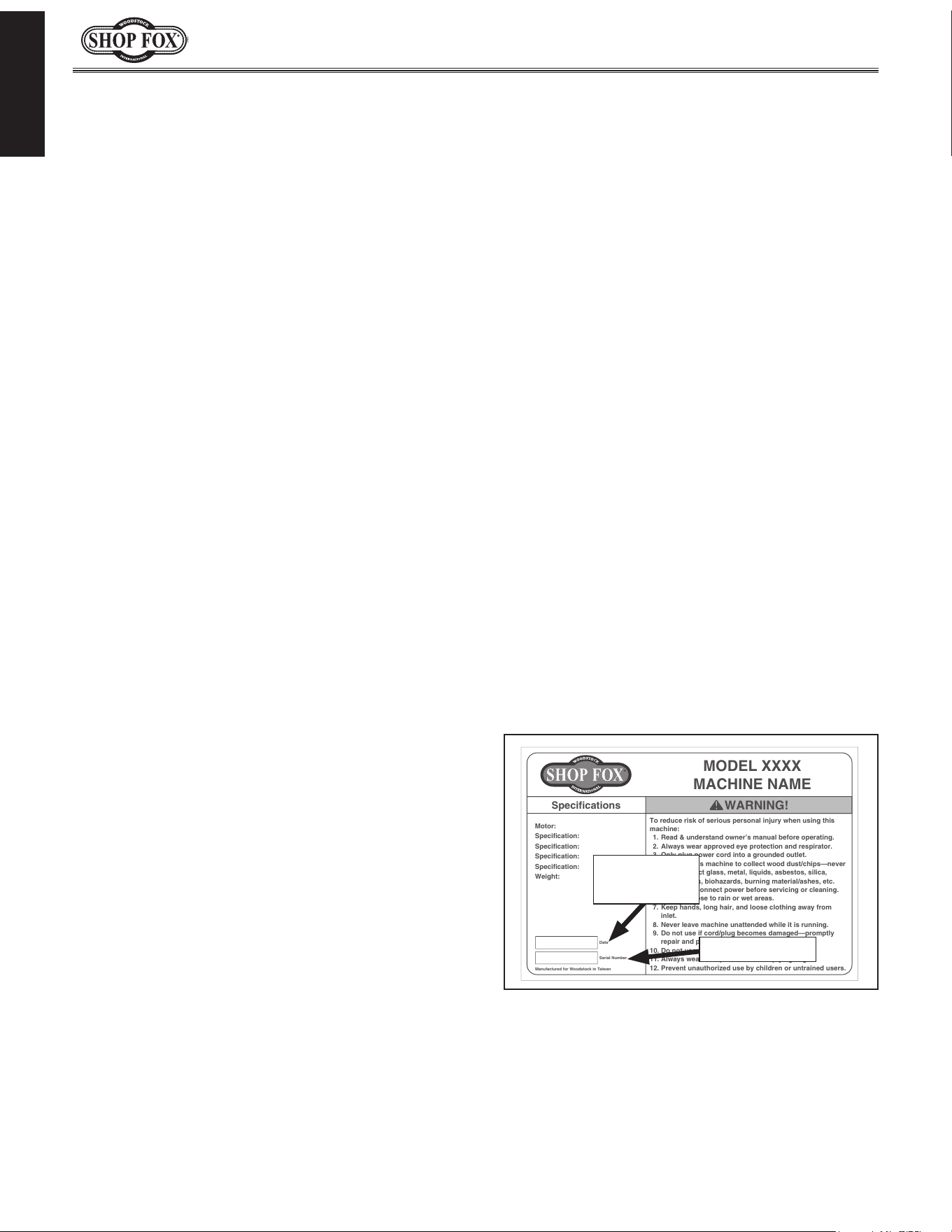
Alternatively, you can call our Technical Support
for help. Before calling, make sure you write
down the
Manufacture.Date and Serial.Number
from the machine ID label (see below). Also, if
available, have a copy of your original.purchase.
receipt on hand. This information is required for
all Tech Support calls.
MODEL XXXX
MACHINE NAME
Motor:
Specification:
Specification:
Specification:
Specification:
Weight:
Specifications
To reduce risk of serious personal injury when using this
machine:
1. Read & understand owner’s manual before operating.
2. Always wear approved eye protection and respirator.
3. Only plug power cord into a grounded outlet.
4. Only use this machine to collect wood dust/chips—never
use to collect glass, metal, liquids, asbestos, silica,
animal parts, biohazards, burning material/ashes, etc.
5. Always disconnect power before servicing or cleaning.
6. Do not expose to rain or wet areas.
7. Keep hands, long hair, and loose clothing away from
inlet.
8. Never leave machine unattended while it is running.
9. Do not use if cord/plug becomes damaged—promptly
repair and protect cord from future damage.
10. Do not use without dust bag or filters in place.
11. Always wear a respirator when emptying bags.
12. Prevent unauthorized use by children or untrained users.
Date
Serial Number
Manufactured for Woodstock in Taiwan
WARNING!
Manufacture
Date
Serial Number
Manual.Accuracy
We are committed to customer satisfaction. If
you have any questions or need help, use the
information below to contact us.
IMPORTANT:.Before.contacting,.please.get.the.
original.purchase.receipt,. serial. number,.and.
manufacture.date.of.your.machine..This.infor-
mation. is. required. for. all. Technical. Support.
calls.and.it.will.help.us.help.you.faster..
Woodstock International Technical Support
Phone: (360) 734-3482
Email: [email protected]
We want your feedback on this manual. What did
you like about it? Where could it be improved?
Please take a few minutes to give us feedback.
Technical Documentation Manager
P.O. Box 2309
Bellingham, WA 98227
Email: [email protected]
Contact.Info
The W1668 is a benchtop drill press. The W1848
is a floor model drill press. With the excep-
tion of the base, column, and flange, these two
machines are exactly the same.

-3-
Model W1668/W1848 (Mfd. Since 08/16)
INTRODUCTION
Model W1668 Machine Specifications, Page 1 of 3
MODEL W1668
131/4" OSCILLATING BENCHTOP DRILL PRESS
Product Dimensions
Weight.......................................................................................................... 113 lbs.
Width (side‐to‐side) x Depth (front‐to‐back) x Height........................................ 15 x 24 x 38 in.
Footprint (Length x Width)......................................................................... 17‐1/2 x 11 in.
Shipping Dimensions
Carton #1
Type............................................................................................. Cardboard Box
Content................................................................................................. Machine
Weight.................................................................................................... 61 lbs.
Length x Width x Height............................................................... 25 x 16 x 10‐3/4 in.
Must Ship Upright............................................................................................ No
Carton #2
Type............................................................................................. Cardboard Box
Content..................................................................................................... Base
Weight.................................................................................................... 62 lbs.
Length x Width x Height........................................................... 32 x 18‐3/4 x 8‐1/2 in.
Must Ship Upright............................................................................................ No
Electrical
Power Requirement.................................................................... 110V, Single‐Phase, 60 Hz
Prewired Voltage................................................................................................. 110V
Full‐Load Current Rating........................................................................................... 9A
Minimum Circuit Size............................................................................................. 15A
Connection Type......................................................................................... Cord & Plug
Power Cord Included.............................................................................................. Yes
Power Cord Length............................................................................................... 9 ft.
Power Cord Gauge............................................................................................ 18 AWG
Plug Included....................................................................................................... Yes
Included Plug Type............................................................................................... 5‐15
Switch Type............................................................ Paddle Safety Switch w/Removable Key
Motors
Main
Horsepower.............................................................................................. 3/4 HP
Phase.............................................................................................. Single‐Phase
Amps........................................................................................................... 9A
Speed.................................................................................................. 1725 RPM
Type......................................................................... TEFC Capacitor‐Start Induction
Power Transfer ................................................................................... V‐Belt Drive
Bearings............................................................... Shielded & Permanently Lubricated
W1668.Machine.Specifications

-4-
Model W1668/W1848 (Mfd. Since 08/16)
INTRODUCTION
Model W1668 Machine Specifications, Page 2 of 3
Main Specifications
Operation Information
Type.................................................................................................. Oscillating
Swing................................................................................................. 13‐1/4 in.
Spindle Taper.............................................................................................. JT33
Spindle Travel........................................................................................ 3‐1/8 in.
Max. Distance From Spindle to Column........................................................... 6‐3/4 in.
Max. Distance From Spindle to Table............................................................ 17‐1/4 in.
Number of Spindle Speeds.................................................................................. 12
Range of Spindle Speeds..................................................................... 250 – 3050 RPM
Max. Head Swivel..................................................................................... 360 deg.
Drilling Capacity (Mild Steel)............................................................... 5/8 in. in Steel
Drill Chuck Type.............................................................................. JT33 Key Chuck
Drill Chuck Size..................................................................................... 1 – 16 mm
Oscillating Stroke Length.............................................................................. 3/4 in.
Spindle Information
Distance From Spindle to Base......................................................................... 24 in.
Quill Diameter........................................................................................ 1.565 in.
Table Information
Max. Table Tilt (Left/Right).......................................................................... 90 deg.
Table Swing............................................................................................ 360 deg.
Table Swivel Around Center........................................................................ 360 deg.
Table Swivel Around Column....................................................................... 360 deg.
Max. Movement of Work Table................................................................... 11‐3/4 in.
Table Diameter...................................................................................... 12‐3/8 in.
Table Thickness............................................................................................ 1 in.
Vertical Table Travel.............................................................. Crank Handle Operation
Number of T‐Slots............................................................................................. 5
T‐Slot Size............................................................................................... 5/8 in.
T‐Slot Centers.............................................................................................. 3 in.
Floor‐To‐Table Height.................................................................... 9‐1/2 – 21‐1/4 in.
Construction
Table............................................................................. Precision‐Ground Cast Iron
Column..................................................................................................... Steel
Spindle Housing....................................................................................... Cast Iron
Head.................................................................................................... Cast Iron
Base.................................................................................................... Cast Iron
Paint Type/Finish...................................................................................... Enamel
Other Related Information
Base Length.......................................................................................... 17‐1/2 in.
Base Width................................................................................................ 11 in.
Column Diameter...................................................................................... 2.79 in.
Depth Stop Type......................................................... Threaded Rod with Positive Stop
Number of Dust Ports......................................................................................... 1
Dust Port Size.............................................................................................. 2 in.
Has Work Light............................................................................................... No

-5-
Model W1668/W1848 (Mfd. Since 08/16)
INTRODUCTION
Model W1848 Machine Specifications, Page 1 of 2
MODEL W1848
131/4" OSCILLATING FLOOR DRILL PRESS
Product Dimensions
Weight.......................................................................................................... 122 lbs.
Width (side‐to‐side) x Depth (front‐to‐back) x Height........................................ 15 x 24 x 63 in.
Footprint (Length x Width)......................................................................... 17‐1/2 x 11 in.
Shipping Dimensions
Type.................................................................................................... Cardboard Box
Content........................................................................................................ Machine
Weight.......................................................................................................... 138 lbs.
Length x Width x Height........................................................................... 58 x 22 x 11 in.
Must Ship Upright.................................................................................................. Yes
Electrical
Power Requirement.................................................................... 110V, Single‐Phase, 60 Hz
Full‐Load Current Rating........................................................................................... 9A
Minimum Circuit Size............................................................................................. 15A
Connection Type......................................................................................... Cord & Plug
Power Cord Included.............................................................................................. Yes
Power Cord Length............................................................................................... 6 ft.
Power Cord Gauge............................................................................................ 18 AWG
Plug Included....................................................................................................... Yes
Included Plug Type............................................................................................... 5‐15
Switch Type............................................................ Paddle Safety Switch w/Removable Key
Motors
Main
Type......................................................................... TEFC Capacitor‐Start Induction
Horsepower.............................................................................................. 3/4 HP
Phase.............................................................................................. Single‐Phase
Amps........................................................................................................... 9A
Speed.................................................................................................. 1725 RPM
Power Transfer ................................................................................... V‐Belt Drive
Bearings............................................................... Shielded & Permanently Lubricated
W18 48.Machine.Sp ecifications

-6-
Model W1668/W1848 (Mfd. Since 08/16)
INTRODUCTION
Model W1848 Machine Specifications, Page 2 of 2
Main Specifications
Operation Information
Type.................................................................................................. Oscillating
Swing................................................................................................. 13‐1/4 in.
Spindle Taper.............................................................................................. JT33
Spindle Travel........................................................................................ 3‐1/8 in.
Max. Distance From Spindle to Column........................................................... 6‐5/8 in.
Number of Spindle Speeds.................................................................................. 12
Range of Spindle Speeds..................................................................... 250 ‐ 3050 RPM
Max. Head Swivel..................................................................................... 360 deg.
Drilling Capacity (Mild Steel)......................................................................... 5/8 in.
Drill Chuck Type.............................................................................. JT33 Key Chuck
Drill Chuck Size..................................................................................... 1 ‐ 16 mm
Oscillating Stroke Length.............................................................................. 3/4 in.
Spindle Information
Quill Diameter........................................................................................ 1.565 in.
Table Information
Max. Table Tilt (Left/Right).......................................................................... 90 deg.
Table Swivel Around Center........................................................................ 360 deg.
Table Swivel Around Column....................................................................... 360 deg.
Max. Movement of Work Table................................................................... 25‐1/4 in.
Table Diameter...................................................................................... 12‐3/8 in.
Table Thickness............................................................................................ 1 in.
Vertical Table Travel.............................................................. Crank Handle Operation
Number of T‐Slots............................................................................................. 5
T‐Slot Size............................................................................................... 1/2 in.
T‐Slot Centers.............................................................................................. 3 in.
Construction
Table............................................................................. Precision‐Ground Cast Iron
Column..................................................................................................... Steel
Spindle Housing....................................................................................... Cast Iron
Head.................................................................................................... Cast Iron
Base.................................................................................................... Cast Iron
Paint Type/Finish...................................................................................... Enamel
Other Related Information
Depth Stop Type............................................................ Threaded Rod w/Positive Stop
Number of Dust Ports......................................................................................... 1
Dust Port Size......................................................................................... 2‐1/4 in.
Has Work Light............................................................................................... No
Other
Country of Origin ............................................................................................... China
Warranty ....................................................................................................... 2 Years
Approximate Assembly & Setup Time ................................................................. 30 Minutes
Serial Number Location .................................................................................... ID Label
ISO 9001 Factory .................................................................................................. Yes
Certified by a Nationally Recognized Testing Laboratory (NRTL) .......................................... No

-7-
Model W1668/W1848 (Mfd. Since 08/16)
SAFETY
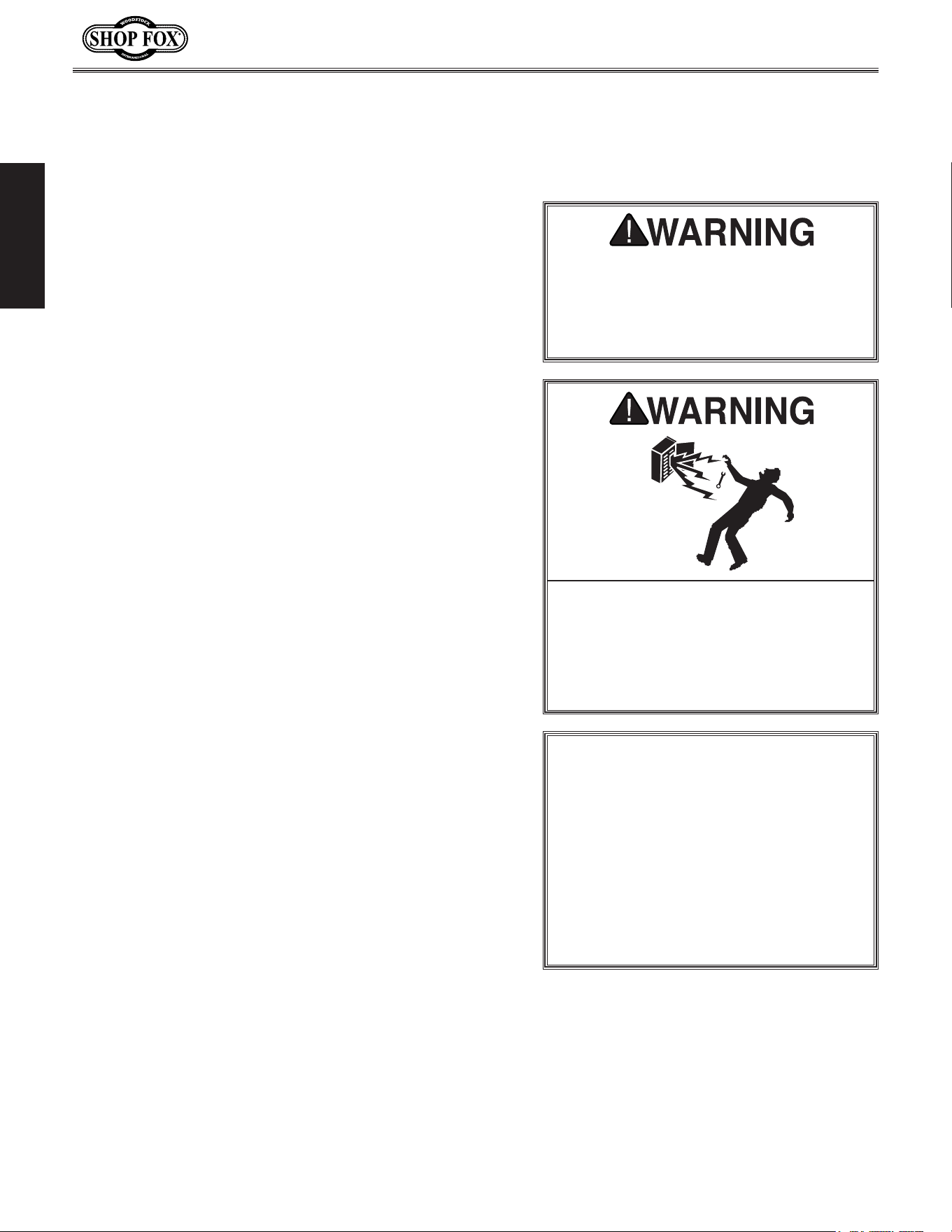
Indicates.a.potentially.hazardous.situation.which,.if.not.avoided,.
MAY.result.in.minor.or.moderate.injury.
Indicates.an.imminently.hazardous.situation.which,.if.not.avoided,.
WILL.result.in.death.or.serious.injury.
Indicates.a.potentially.hazardous.situation.which,.if.not.avoided,.
COULD.result.in.death.or.serious.injury.
This.symbol.is.used.to.alert.the.user.to.useful.information.about.
proper.operation.of.the.equipment.or.a.situation.that.may.cause.
damage.to.the.machinery.
NOTICE
SAFETY
OWNER’S.MANUAL..
Read and understand this
owner’s manual BEFORE using machine.
TRAINED.OPERATORS.ONLY..
Untrained operators
have a higher risk of being hurt or killed. Only
allow trained/supervised people to use this
machine. When machine is not being used,
disconnect power, remove switch keys, or
lock-out machine to prevent unauthorized
use—especially around children. Make
workshop kid proof!
DANGEROUS.ENVIRONMENTS..
Do not use
machinery in areas that are wet, cluttered,
or have poor lighting. Operating machinery
in these areas greatly increases the risk of
accidents and injury.
MENTAL.ALERTNESS.REQUIRED..
Full mental
alertness is required for safe operation of
machinery. Never operate under the influence
of drugs or alcohol, when tired, or when
distracted.
ELECTRICAL.EQUIPMENT.INJURY.RISKS..You can
be shocked, burned, or killed by touching live
electrical components or improperly grounded
machinery. To reduce this risk, only allow an
electrician or qualified service personnel to
do electrical installation or repair work, and
always disconnect power before accessing or
exposing electrical equipment.
DISCONNECT.POWER.FIRST..Always disconnect
machine from power supply BEFORE making
adjustments, changing tooling, or servicing
machine. This eliminates the risk of injury
from unintended startup or contact with live
electrical components.
EYE.PROTECTION..Always wear ANSI-approved
safety glasses or a face shield when operating
or observing machinery to reduce the risk of
eye injury or blindness from flying particles.
Everyday eyeglasses are not approved safety
glasses.
Standard.Machinery.Safety.I nstructions
For.Your.Own.Safet y,
Read.Manual.Before .Operating.Machine
The. purpose. of. safety. symbols. is. to. attract. your. attention. to. possible. hazardous. conditions.. This.
manual.uses.a.series.of.symbols.and.signal.words.intended.to.convey.the.level.of.importance.of.the.
safety.messages..The. progression.of.symbols.is.described.below..Remember.that.safety.messages.by.
themselves. do. not.eliminate.danger.and.are. not.a.substitute.for.proper. accident. prevention.mea-
sures—this.responsibility.is.ultimately.up.to.the.operator!
SAFETY
Standard.Machinery.Safety.Instructions

-8-
Model W1668/W1848 (Mfd. Since 08/16)
SAFETY
WEARING.PROPER.APPAREL..Do not wear
clothing, apparel, or jewelry that can become
entangled in moving parts. Always tie back
or cover long hair. Wear non-slip footwear to
avoid accidental slips, which could cause loss
of workpiece control.
HAZARDOUS
.DUST..Dust created while using
machinery may cause cancer, birth defects,
or long-term respiratory damage. Be aware of
dust hazards associated with each workpiece
material, and always wear a NIOSH-approved
respirator to reduce your risk.
HEARING.PROTECTION..
Always wear hearing
protection when operating or observing
loud machinery. Extended exposure to this
noise without hearing protection can cause
permanent hearing loss.
REMOVE.ADJUSTING.TOOLS..
Tools left on
machinery can become dangerous projectiles
upon startup. Never leave chuck keys,
wrenches, or any other tools on machine.
Always verify removal before starting!
INTENDED.USAGE..
Only use machine for its
intended purpose—never make modifications
without prior approval from Woodstock
International. Modifying machine or using
it differently than intended will void the
warranty and may result in malfunction or
mechanical failure that leads to serious
personal injury or death!
AWKWARD.POSITIONS..
Keep proper footing and
balance at all times when operating machine.
Do not overreach! Avoid awkward hand
positions that make workpiece control difficult
or increase the risk of accidental injury.
CHILDREN.&.BYSTANDERS..
Keep children and
bystanders at a safe distance from the work
area. Stop using machine if they become a
distraction.
GUARDS.&.COVERS..
Guards and covers reduce
accidental contact with moving parts or flying
debris—make sure they are properly installed,
undamaged, and working correctly.
FORCING.MACHINERY..Do not force machine. It
will do the job safer and better at the rate for
which it was designed.
NEVER.STAND.ON.MACHINE..Serious injury may
occur if machine is tipped or if the cutting
tool is unintentionally contacted.
STABLE.MACHINE..Unexpected movement during
operation greatly increases risk of injury or
loss of control. Before starting, verify machine
is stable and mobile base (if used) is locked.
USE.RECOMMENDED.ACCESSORIES..Consult
this owner’s manual or the manufacturer for
recommended accessories. Using improper
accessories will increase risk of serious injury.
UNATTENDED.OPERATION..To reduce the risk
of accidental injury, turn machine OFF and
ensure all moving parts completely stop
before walking away. Never leave machine
running while unattended.
MAINTAIN.WITH.CARE..Follow all maintenance
instructions and lubrication schedules to
keep machine in good working condition. A
machine that is improperly maintained could
malfunction, leading to serious personal injury
or death.
CHECK.DAMAGED.PARTS..Regularly inspect
machine for any condition that may affect
safe operation. Immediately repair or replace
damaged or mis-adjusted parts before
operating machine.
MAINTAIN.POWER.CORDS..When disconnecting
cord-connected machines from power, grab
and pull the plug—NOT the cord. Pulling the
cord may damage the wires inside, resulting
in a short. Do not handle cord/plug with wet
hands. Avoid cord damage by keeping it away
from heated surfaces, high traffic areas, harsh
chemicals, and wet/damp locations.
EXPERIENCING.DIFFICULTIES..If at any time
you experience difficulties performing the
intended operation, stop using the machine!
Contact Technical Support at (360) 734-3482.

-9-
Model W1668/W1848 (Mfd. Since 08/16)
SAFETY
Serious injury or death can occur from getting clothing, jewelry, or long hair entangled in rotat-
ing spindle or bit/cutting tool. Contact with rotating bit/cutting tool can result in severe cuts or
amputation of fingers. Flying metal chips can cause blindness or eye injuries. Broken bits/cutting
tools, unsecured workpieces, chuck keys, or other adjustment tools thrown from rotating spindle
can strike nearby operator or bystanders with great force. To reduce the risk of these hazards,
operator and bystanders MUST completely heed hazards and warnings below.
WORKPIECE CONTROL. An unsecured workpiece
may unexpectedly shift, spin out of control,
or be thrown if bit/cutting tool “grabs” during
operation. Clamp workpiece to table or in table-
mounted vise, or brace against column to prevent
rotation.
NEVER hold workpiece by hand during
operation.
NEVER start machine with bit/cutting
tool touching workpiece; allow spindle to gain full
speed before drilling.
INSPECTING BIT/CUTTING TOOL. Damaged bits/
cutting tools may break apart during operation
and hit operator or bystanders. Dull bits/cutting
tools increase cutting resistance and are more
likely to grab and spin/throw workpiece. Always
inspect bits/cutting tools for sharpness, chips, or
cracks before each use. Replace dull, chipped, or
cracked bits/cutting tools immediately.
MAINTAINING MACHINE. Keep machine in proper
working condition to help ensure that it functions
safely and all guards and other components work
as intended. Perform routine inspections and all
necessary maintenance. Never operate machine
with damaged or worn parts that can break or
result in unexpected movement during operation.
CLEANING MACHINE SAFELY.
To avoid contact
with tool/bit, n
ever clear chips while spindle is
turning. To avoid cuts and eye injuries, DO NOT
clear chips by hand or with compressed air—use a
brush or vacuum instead.
DISCONNECT POWER FIRST. To
reduce risk of
electrocution or injury from unexpected startup,
make sure drill is turned OFF, disconnected from
power, and all moving parts have come to a com-
plete stop before changing bits/cutting tools or
starting any inspection, adjustment, or mainte-
nance procedure.
WEARING PROPER PPE. Flying chips created
by drilling can cause eye injuries or blindness.
Always wear a face shield in addition to safety
glasses. Always keep hands and fingers away from
drill bit/cutting tool. Avoid awkward hand posi-
tions, where a sudden slip could cause hand to
move into bit/cutting tool.
AVOIDING ENTANGLEMENT. DO NOT wear loose
clothing, gloves, or jewelry, and tie back long
hair. Keep all guards in place and secure. Always
allow spindle to stop on its own. DO NOT stop
spindle using your hand or any other object.
REMOVING ADJUSTMENT TOOLS. Chuck key,
drawbar wrench, and other tools left on machine
can become deadly projectiles when spindle is
started. Remove all loose items or tools used on
spindle immediately after use.
SECURING BIT/CUTTING TOOL. Firmly secure bit/
cutting tool so it does not fly out of spindle during
operation or startup.
SECURING TABLE AND HEADSTOCK. To avoid
accidental contact with tool/bit, tighten all table
and headstock locks before operating drill.
CORRECT SPINDLE SPEED. Using wrong spindle
speed can cause bits/cutting tools to break and
strike operator or bystanders. Follow recom-
mended speeds and feeds for each size/type of
bit/cutting tool and workpiece material.
WORKPIECE PREPARATION. To avoid loss of
workpiece control, DO NOT drill material with
an uneven surface on the table, unless a suitable
support is used. To avoid impact injuries, make
sure workpiece is free of nails or foreign objects
in area to be drilled.
Additional.Safet y .for.Drill.Presses
-10-
Model W1668/W1848 (Mfd. Since 08/16)
SAFETY
ELECTRICAL
Circui t.Requirements
This machine must be connected to the correct size and
type of power supply circuit, or fire or electrical damage
may occur. Read through this section to determine if an
adequate power supply circuit is available. If a correct
circuit is not available, a qualified electrician MUST install
one before you can connect the machine to power.
A power supply circuit includes all electrical equipment
between the breaker box or fuse panel in the building
and the machine. The power supply circuit used for
this machine must be sized to safely handle the full-
load current drawn from the machine for an extended
period of time. (If this machine is connected to a circuit
protected by fuses, use a time delay fuse marked D.)
Circuit.Requirements.for.110V
This machine is prewired to operate on a power supply
circuit that has a verified ground and meets the following
requirements:
Circuit.Type................ 110V/120V,.60.Hz,.Single-Phase
Circuit.Size.............................................. 15.Amps
Plug/Receptacle..................................... NEMA.5-15
Full-Load.Current.Rating
The full-load current rating is the amperage a machine
draws at 100% of the rated output power. On machines
with multiple motors, this is the amperage drawn by the
largest motor or sum of all motors and electrical devices
that might operate at one time during normal operations.
Full-Load.Current.Rating.at.110V.....................9.Amps
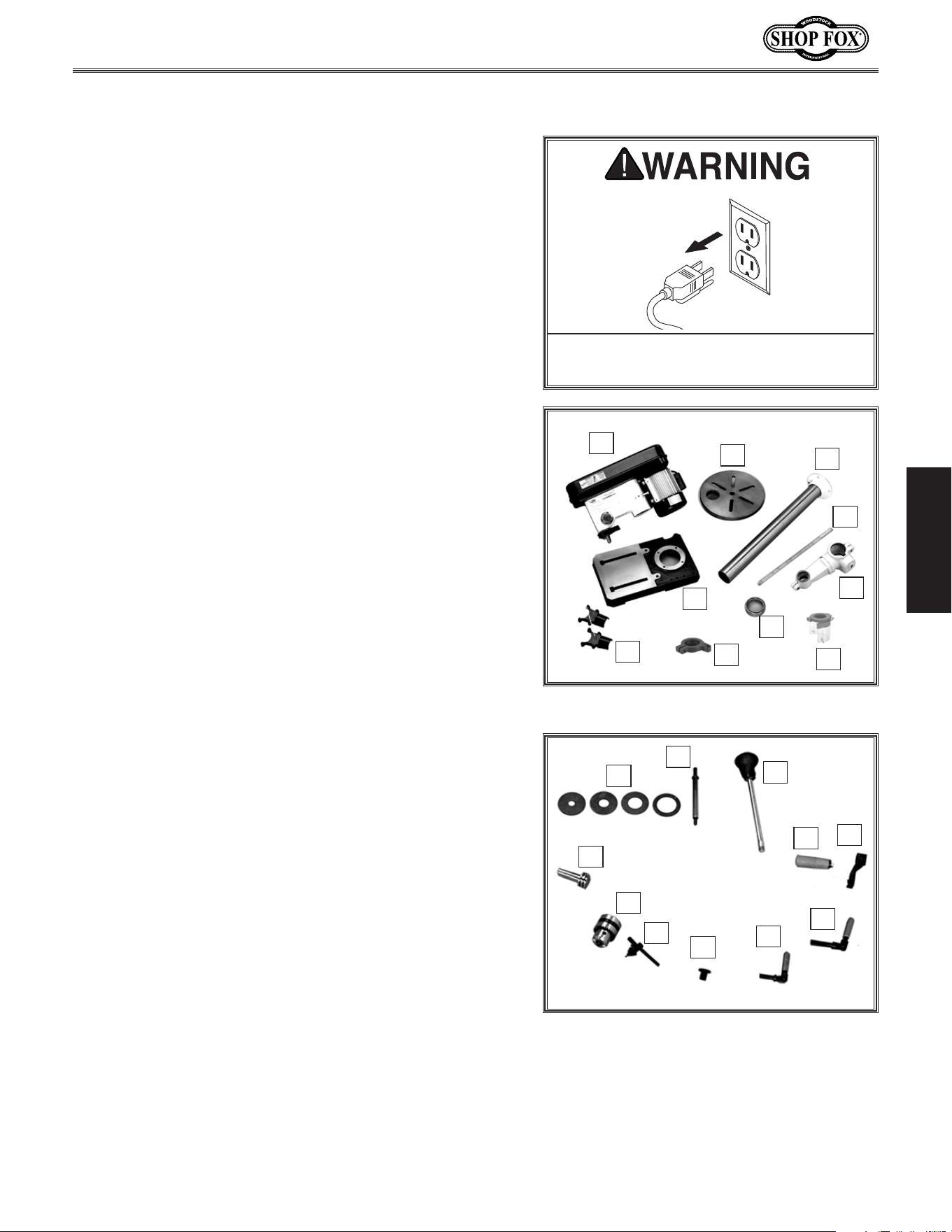
The. machine. must. be. properly. set. up.
before. it. is. safe. to. operate.. DO. NOT.
connect. this. machine. to. the. power.
source.until.instructed.to.do.so.later.in.
this.manual.
Incorrectly. wiring. or. grounding. this.
machine.can.cause.electrocution,.fire,.
or.machine.damage..To.reduce.this.risk,.
only.an.electrician.or.qualified.service.
personnel. should. do. any. required.
electrical.work.on.this.machine.
NOTICE
The.circuit.requirements. listed. in.this.
manual. apply. to
.a.dedicated.circuit—
where.only.one.machine.will.be.running.
at. a. time.. If. this. machine. will. be.
connected. to. a. shared. circuit. where.
multiple.machines.will.be.running.at.the.
same.time,.consult.with.an.electrician.
to. ensure. that. the. circuit. is. properly.
sized.for.safe.operation.
-11-
Model W1668/W1848 (Mfd. Since 08/16)
ELECTRICAL
Groun ding.Requirements
This machine MUST be grounded. In the event of certain
types of
malfunctions or breakdowns, grounding provides
a path of least resistance for electric current
to travel—in
order
to reduce the risk of electric shock.
Improper connection of the equipment-grounding
wire
will
increase
the risk of electric shock. The wire with green
insulation
(with/without yellow stripes) is the equipment-
grounding
wire. If repair or replacement of the power
cord or plug is necessary, do not connect the equipment-
grounding
wire to a live (current carrying) terminal.
Check with a qualified electrician or service personnel
if
you do not understand these grounding requirements,
or if
you are in doubt about whether the tool is
properly grounded.
If you ever notice that a cord or
plug is damaged or worn, disconnect it from power, and
immediately replace it with a new one.
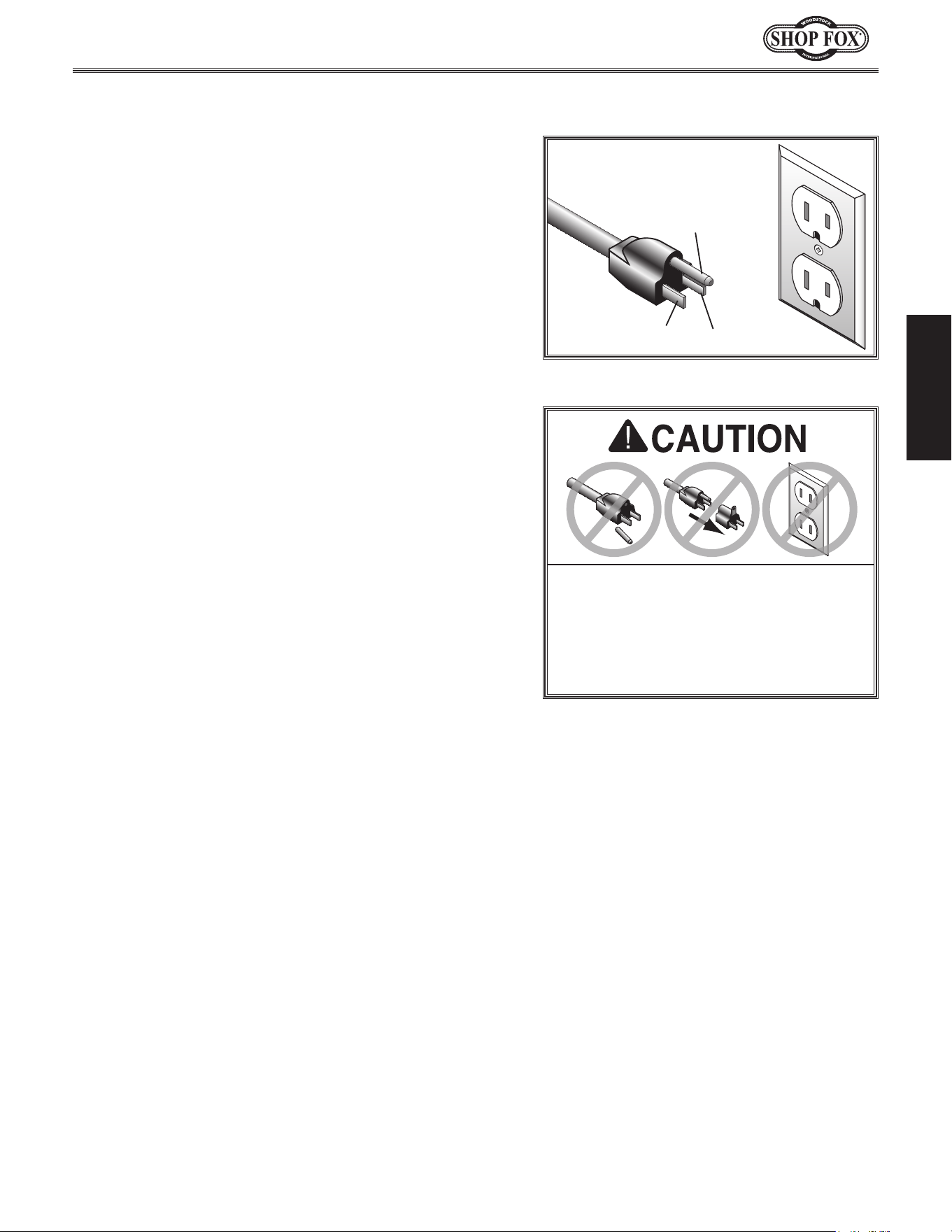
Grounding Prong
Neutral Hot
5-15 PLUG
GROUNDED
5-15 RECEPTACLE
110V
Figure.1. NEMA 5-15 plug & receptacle.
DO. NOT. modify. the. provided. plug. or.
use. an. adapter. if. the. plug. will. not.
fit . the. receptacle.. Instead,. have. an.
electrician.install.the.proper.receptacle.
on. a. power. supply. circuit. that. meets.
the.requirements.for. this.machine.
Extension.Cords
We do not recommend using an extension cord with
this machine. Extension cords cause voltage drop, which
may damage electrical components and shorten motor
life. Voltage drop increases with longer extension cords
and smaller gauge sizes (higher gauge numbers indicate
smaller sizes).
Any extension cord used with this machine must contain a
ground wire, match the required
plug and receptacle, and
meet the following requirements:
Minimum.Gauge.Size.at.110V....................... 14.AWG
Maximum.Length.(Shorter.is.Better).................50.ft.
For.110V.Connection.
This machine is equipped with a power cord with an
equipment-grounding
wire and NE M A 5-15 grounding
plug
(see figure). The plug must only be inserted into
a matching
receptacle that is properly installed and
grounded in accordance with local codes and ordinances.

-12-
Model W1668/W1848 (Mfd. Since 08/16)
SETUP
SETU P
SUFFOCATION HAZARD!
Immediately discard all
plastic bags and packing
materials to eliminate
choking/suffocation
hazards for children and
animals.
USE. helpers. o r. power.
lifting. equipment. to. lift.
this. machine.. Otherwise,.
serious. personal. injury.
may.occur..
Wear safety glasses during
entire setup process!
This machine presents
serious injury hazards
to untrained users. Read
through this entire manual
to become familiar with
the controls and opera-
tions before starting the
machine!
Description. Qty
• Safety Glasses for Each Person ..........................1
• Degreaser or Solvent for Cleaning ................Varies
• Disposable Rags for Cleaning ......................Varies
• Straightedge ................................................1
• Plumb Bob ..................................................1
• Dust Collection System ...................................1
• Dust Hose 2" ...............................................1
• Hose Clamp 2" .............................................1
• Phillips Head Screwdriver ................................1
• Hex Wrench 16mm ........................................1
• Assistant for Lifting .......................................1
Items.Needed.for.Setup
Unpacking
This machine has been carefully packaged for safe
transportation. If you notice the machine has been
damaged during shipping, please contact your authorized
Shop Fox dealer immediately.
The following items are needed, but not included, to set
up your machine.
-13-
Model W1668/W1848 (Mfd. Since 08/16)
SETUP
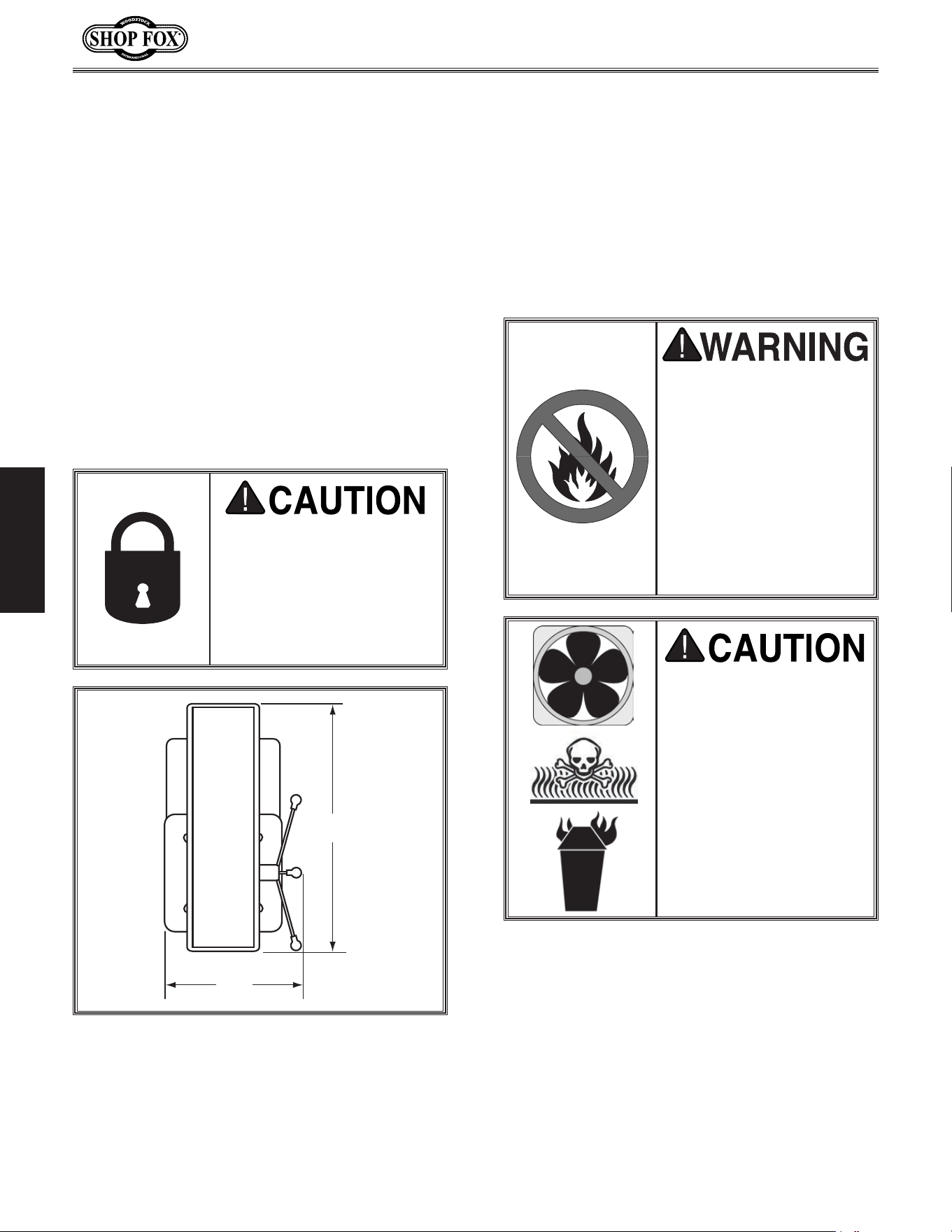
Box.Inventory.(Figures.2.&.3). Qty
A. Headstock Assembly .......................................1
B. Table .........................................................1
C. Column ......................................................1
D. Rack .........................................................1
E. Table Bracket ..............................................1
F. Rack Ring ...................................................1
G. Base ..........................................................1
H. Dust Port Halves ...........................................2
I. Depth Stop Bracket .......................................1
J. Chuck Guard Assembly ....................................1
K. Table Inserts (
5
⁄8", 1", 1
3
⁄8", 1
7
⁄8") ..................1 ea
L. Sanding Mandrel ...........................................1
M.. Spindle Handles ............................................3
N. Hand Crank Handle ........................................1
O. Hand Crank .................................................1
P. Lock Handle M12-1.75 ....................................1
Q. Lock Handle M10-1.5 ......................................1
R. Belt Cover Knob ............................................1
S. Key ...........................................................1
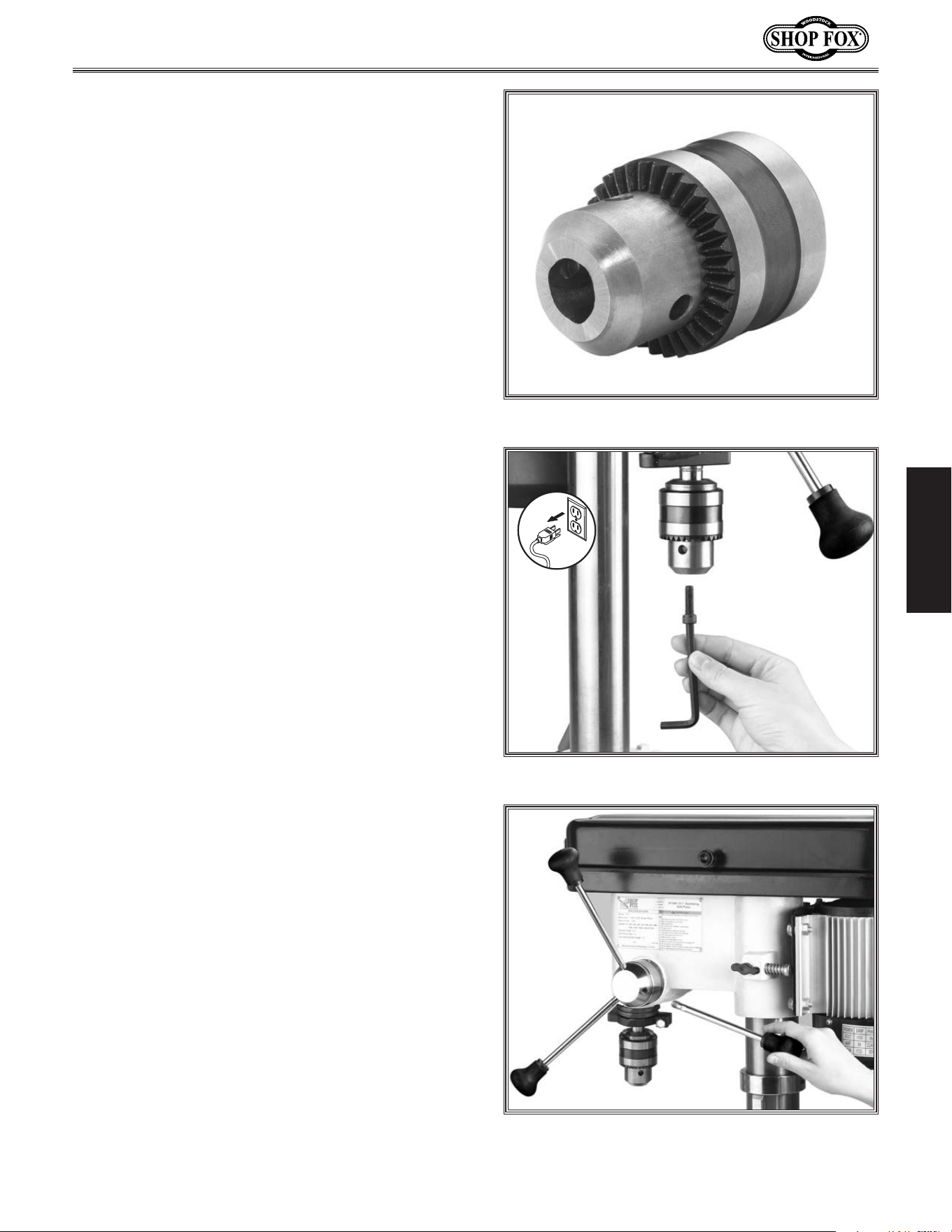
T. Drill Chuck JT33 ...........................................1
U.. Pinion Gear .................................................1
V.. Spindle Sander Set D2877 (not shown) .................1
W.. Motor Lock Screw M8-1.25 X 25 (not shown) .........1
Tools.and.Fasteners.(not.shown). Qty.
—Special Wrench 25mm ..................................1
—Open End Wrench 13 x 14 ..............................1
—Hex Wrenches 3, 4, 5mm .........................1 ea.
—Hex Nut M8-1.25 (Mandrel) ............................1
—Mandrel Washers
3
⁄4" OD x
5
⁄8" ID (Mandrel) ........2
—Mandrel Washer
7
⁄8" OD x
3
⁄8" ID (Mandrel) .........1
—Mandrel Washer
5
⁄8" OD x
3
⁄8" ID (Mandrel) .........1
—Hex Bolts M10-1.5 x 25 (Colum/Base) ................4
—Phillips Head Screws M4-.7 x 22 (Dust Port) ........4
—Cap Screw M5-.8 x 20 (Chuck).........................1
Inventory
Figure.3. Additional W1668/W1848
inventory items.
O
P
Q
R
S
K
L
M
N
The following is a list of items shipped with your machine.
Before beginning setup, lay these items out and inventory
them.
Note:
If you cannot find an item on this list, carefully
check around/inside the machine and packaging materials.
Often, these items get lost in packaging materials while
unpacking or they are pre-installed at the factory.
Keep. machine. disconnected. from.
power.until.instructed.otherwise.
T
U
Figure.2. W1668/W1848 inventory.
I
B
A
H
C
D
E
F
G
J
I
-14-
Model W1668/W1848 (Mfd. Since 08/16)
SETUP
•. Floor.&.Workbench.Load: Refer to
the Machine.Data.Sheet for weight
and footprint specifications for your
machine. Some residential floors (W1848)
and workbenches (W1668) may require
additional reinforcement to support the
machine.
•. Working.Clearances: Consider existing and
anticipated needs, size of material to be
processed through each machine, and space
for auxiliary stands, work tables, or other
machinery when establishing a location for
your machine. See Figure 4 for the minimum
working clearances of the Model W1668/
W1848.
INJURY.HAZARD!.Untrained.
users.can.injure.themselves.
with.this.machine..Restrict.
acce ss. to. machine. w hen.
you.are.away,. especially.if.
it. is. installed. where. chil-
dren.are.present.
Cleaning.Machin e
The table and other unpainted parts of your
machine are coated with a waxy grease that
protects them from corrosion during shipment.
Clean this grease off with a solvent cleaner or
citrus-based degreaser. DO NOT use chlorine-
based solvents such as brake parts cleaner or
acetone—if you happen to splash some onto a
painted surface, you will ruin the finish.
Machine.Placement
NEVER.clean.with.gasoline.
or. other. petroleum-
based.solvents..Most.have.
low. flash. points,. which.
make. them. extremely.
flammable.. A. risk. of.
explosion. and. burning.
exists. if. these. products.
are.used..Serious.personal.
injury. may. occur. if. this.
warning.is.ignored!
ALWAYS. work. in. well-
ventilated.areas.far.from.
possible. ignition. sources.
when. using. solvents. to.
clean. machinery.. Many.
solvents. are. toxic. when.
inhaled. or. ingested.. Use.
care. when. disposing.
of. waste. rags. and.
towels. to. be. sure. they.
DO. NOT. create. fire. or.
environmental.hazards..
15"
24"
Figure.4. Working clearances.
-15-
Model W1668/W1848 (Mfd. Since 08/16)
SETUP
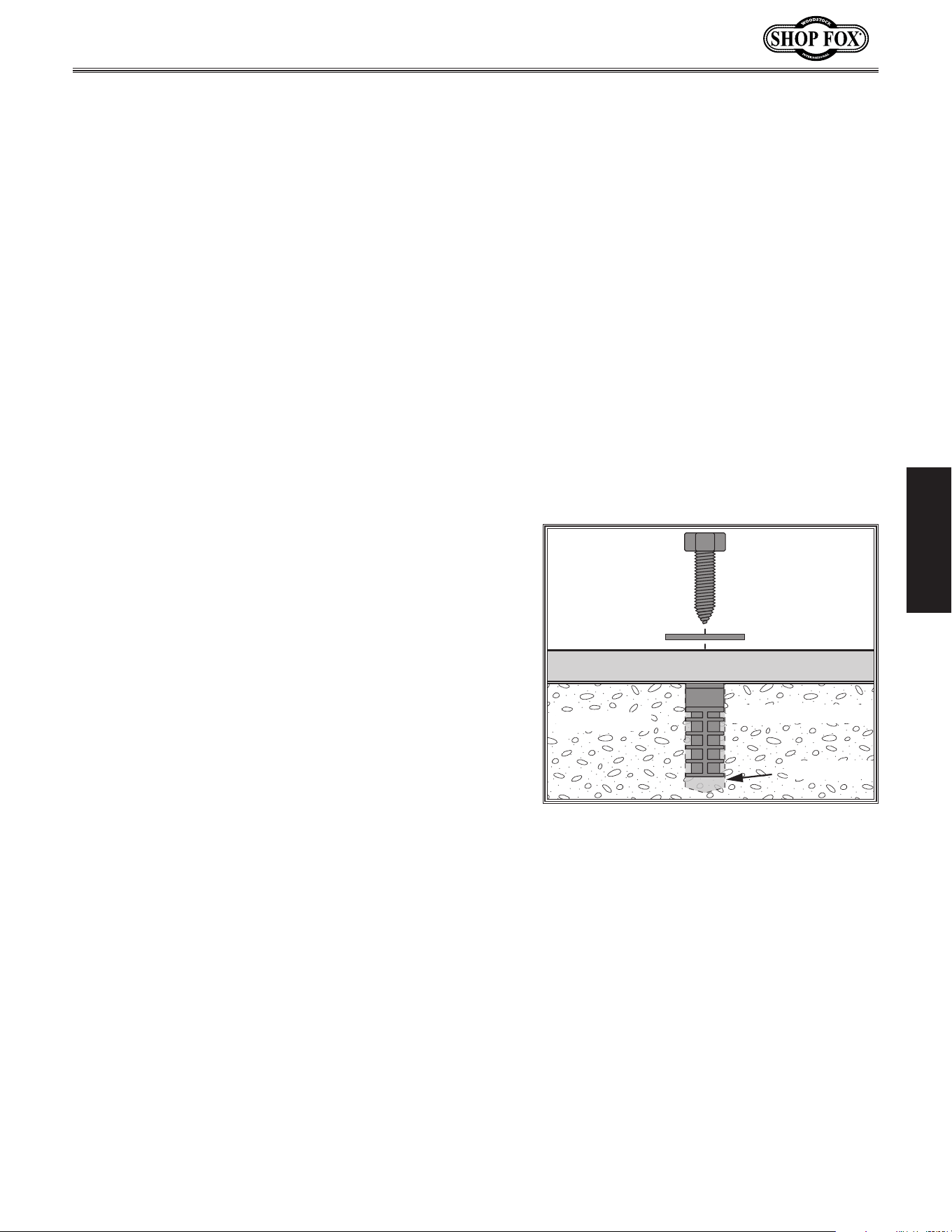
Anchoring.to.Floor.(W1848)
Machine Base
Concrete
Lag Screw
Lag Shield Anchor
Flat Washer
Drilled Hole
Figure.5. Popular method for anchoring
machinery to a concrete floor.
Number.of.Mounting.Holes................................... 8
Diameter.of.Mounting.Hardware......
5
⁄16".(6).&..
1
⁄2".(2).
Anchoring machinery to the floor prevents tipping or
shifting and reduces vibration that may occur during
operation, resulting in a machine that runs slightly quieter
and feels more solid.
If the machine will be installed in a commercial or
workplace setting, or if it is permanently connected
(hardwired) to the power supply, local codes may require
that it be anchored to the floor.
If not required by any local codes, fastening the machine
to the floor is an optional step. If you choose not to do
this with your machine, we recommend placing it on
machine mounts, as these provide an easy method for
leveling and they have vibration-absorbing pads.
Anchoring.to.Concrete.Floors
Lag shield anchors with lag screws (see Figure) are a
popular way to anchor machinery to a concrete floor,
because the anchors sit flush with the floor surface,
making it easy to unbolt and move the machine later, if
needed. However, anytime local codes apply, you MUST
follow the anchoring methodology specified by the code.
-16-
Model W1668/W1848 (Mfd. Since 08/16)
SETUP
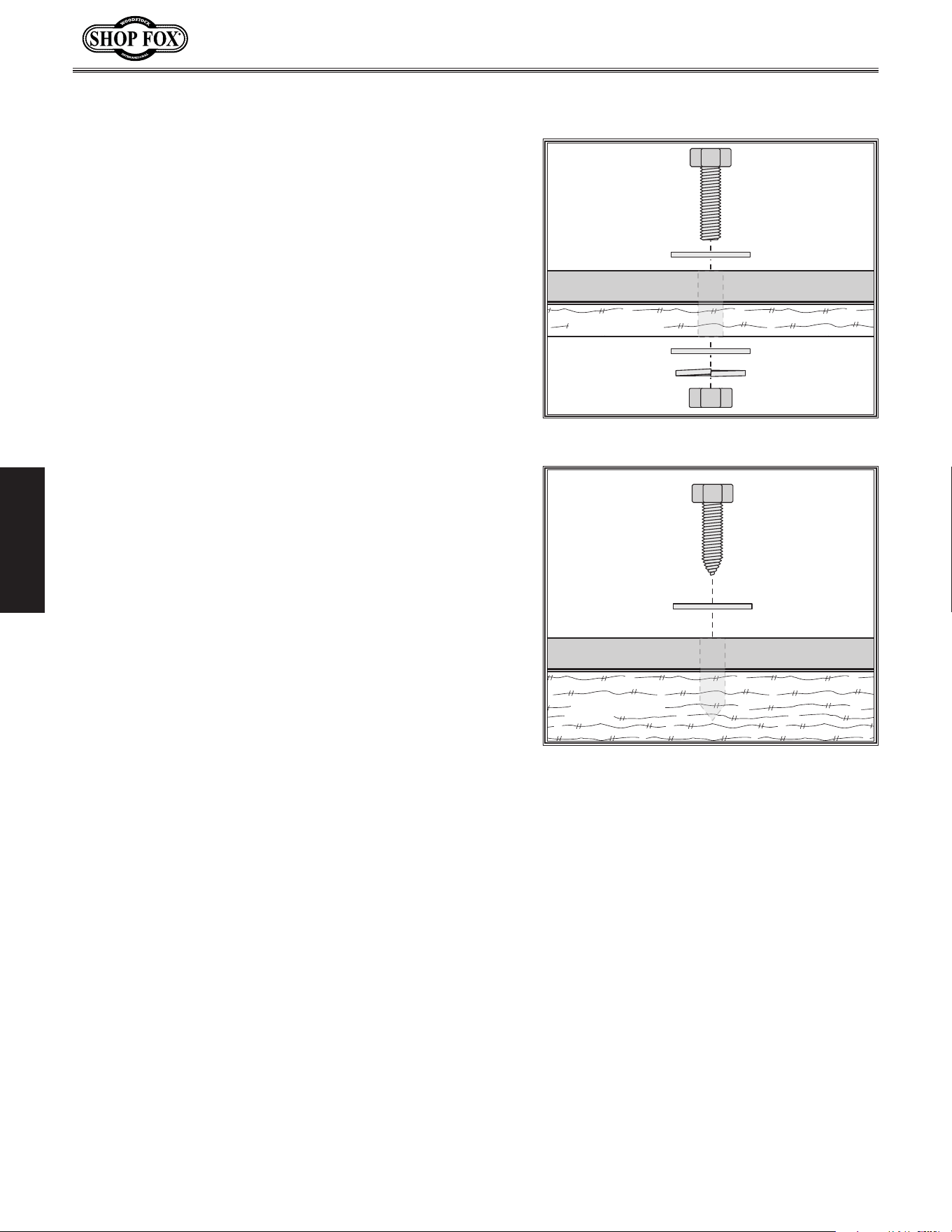
Bench.M ounting.(W1668)
Number.of.Mounting.Holes................................... 8
Diameter.of.Mounting.Hardware......
5
⁄16".(6).&..
1
⁄2".(2)
Machine Base
Workbench
Bolt
Flat Washer
Flat Washer
Lock Washer
Hex Nut
Figure.6. Typical "Through Mount" setup.
Machine Base
Workbench
Lag Screw
Flat Washer
Figure.7. Typical "Direct Mount" setup.
The base of this machine has mounting holes that allow it
to be fastened to a workbench or other mounting surface
to prevent it from moving during operation and causing
accidental injury or damage.
The strongest mounting option is a “Through Mount” (see
example) where holes are drilled all the way through the
workbench—and hex bolts, washers, and hex nuts are
used to secure the machine in place.
Another option is a “Direct Mount” (see example) where
the machine is secured directly to the workbench with lag
screws and washers.
-17-
Model W1668/W1848 (Mfd. Since 08/16)
SETUP
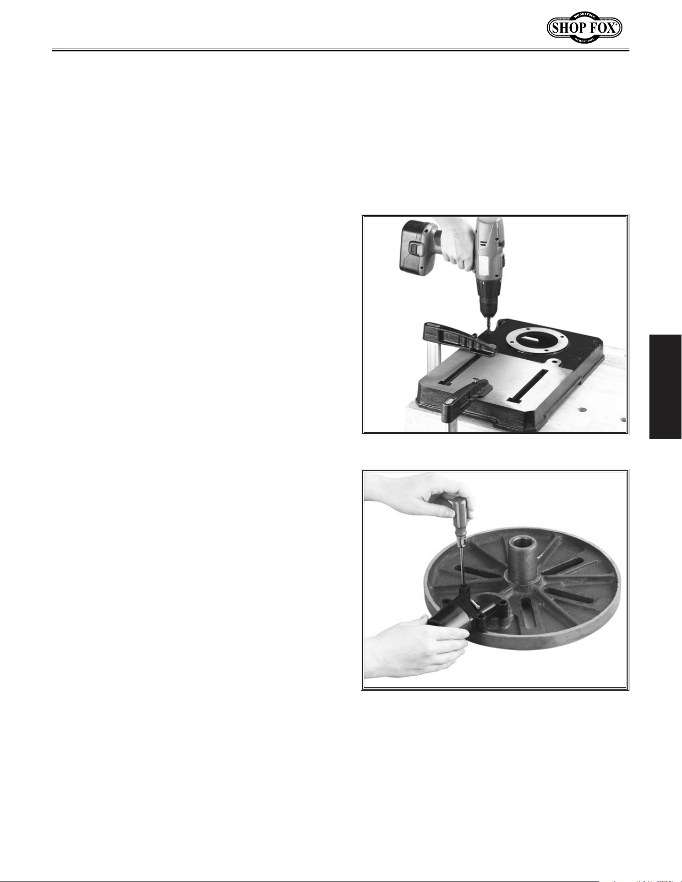
Figure.8..Using holes as a drill guide.
Figure.9..Installing the dust port.
Assembly
Before beginning the assembly process, refer to
Items.Needed.for.Setup and gather everything
you need. Ensure all parts have been properly
cleaned of the heavy-duty rust-preventative
applied at the factory, if applicable. Be sure to
complete all steps in the assembly procedure
prior to performing the Test. Run.
To.assemble.the.drill.press,.do.these.steps:
1. Position the drill press base on a flat and
stable surface.
2.. Secure the base to the mounting surface
(Refer to Pages. 8–9).
3. Place the column on the base, line up the
four mounting holes, and secure tightly
with the four M10-1.5 x 25 hex bolts, using
a 16mm wrench.
4. Bring the dust port halves together, align
the mounting holes on the dust port and
table, then secure with the four M4-.7 x 22
Philips head screws, as shown in Figure.9.
-18-
Model W1668/W1848 (Mfd. Since 08/16)
SETUP
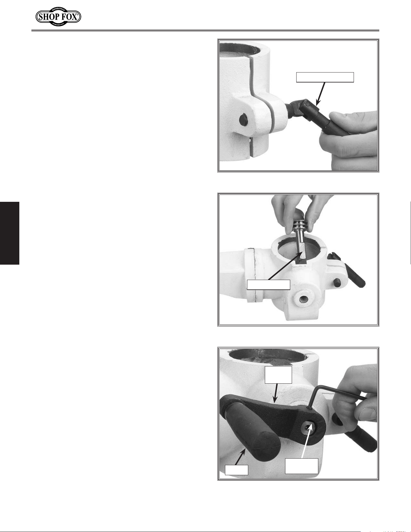
7. Insert the 12mm lock handle into the table
support bracket through the blind hole,
into the threaded hole, and thread inward
three turns, as shown in Figure.10.
Figure.12..Crank and set screw positioning.
Flat.on.
Pinion
Crank.
Handle
Handle
Figure.11..Pinion installation positioning.
Flat.on.Pinion
Figure.10. Loosely installing table lock lever.
12mm.Lock.Handle
9. Align the set screw in the crank handle
with the flat on the pinion shaft and tight-
en, as shown in Figure.12.
10. Thread the handle into the crank handle
(Figure.12).
11. If the column ring is installed on the
colum, loosen the set screw on the ring and
remove it.
8. If the pinion is not already installed, insert
it shaft-end into the hole on the side of the
table support bracket, as shown in Figure.
11.
-19-
Model W1668/W1848 (Mfd. Since 08/16)
SETUP
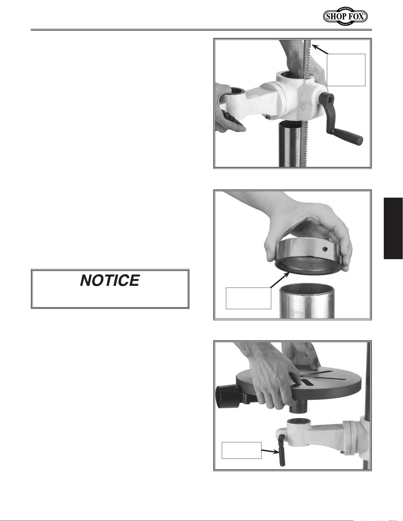
Figure.13. Rack, column, table support position.
12. Position the rack so the long un-toothed
end is facing upward (see Figure.13).
13. Insert the rack into the table support
bracket so the teeth face out and mesh
with the pinion (see Figure.13).
14.. While holding the rack in place, slide the
table support bracket onto the column.
15.. Allow the bracket and rack to slide down
until the bottom of the rack bevel slips into
the tapered shoulder on the column sup-
port.
16. Slide the column ring onto the column with
the inside bevel in the down position (see
Figure.14).
.
17.. Adjust the ring until the tip of the rack
fits inside the bevel, and
the rack rotates
freely when you rotate the table support
around the column.
18..Secure the table support with the table
lock lever.
Figure.14..Column ring bevel positioning.
Column.Ring.
Bevel.Facing.
Downward
Figure.15..Table installation.
10mm.Lock.
Handle
Long.
Un-toothed.
Rack.End.is.
Facing.
Upward
19. Carefully tighten the set screw on the ring.
20.. Thread the 10mm lock handle into the
table bracket through the blind hole, into
the threaded hole, and thread inward three
turns.
21.. Align the shaft under the table with the
hole on the end of the table support brack-
et and install (see Figure.15).
22..Tighten the table lock lever.
Use. caution. when. tightening. the. set. screw..
Over.tightening.will.split.the.column.ring.
-20-
Model W1668/W1848 (Mfd. Since 08/16)
SETUP
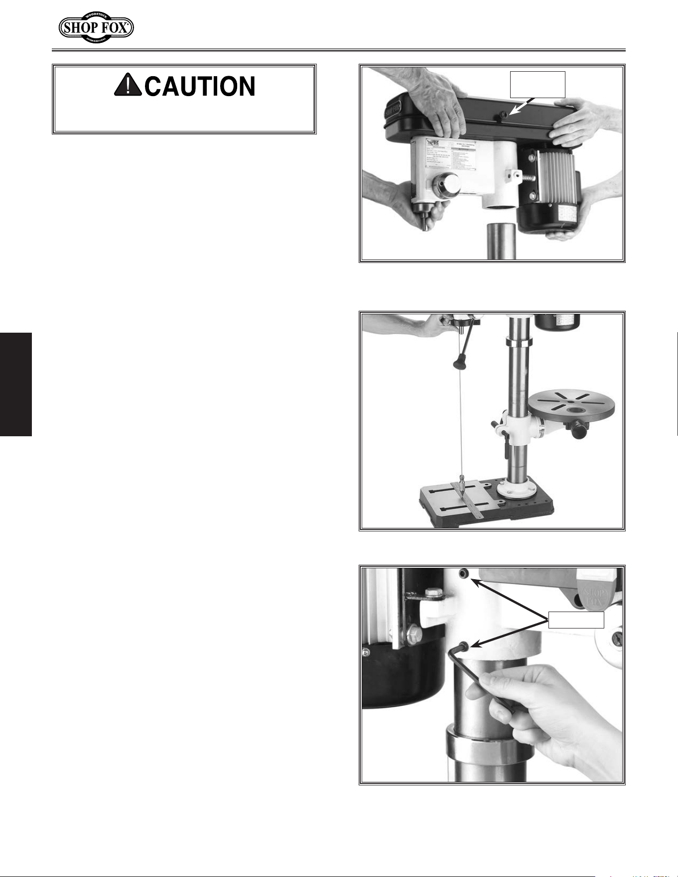
Figure.17..Aligning headstock with base.
Figure.18..Securing the headstock to the
column.
Set.Screws
Figure.16..Aligning the pocket in the headstock
with the column.
Belt.Cover.
Knob
23. With an assistant, position the pocket
over the column (Figure.16).and allow
the headstock to slide down until the col-
umn fully seats up and into the headstock
(approximately 3
1
⁄2").
Tip: Place a few drops of multi-purpose
grease on the column to help the head-
stock seat more easily.
DO.NOT over tighten the set screws and strip
the threads or bend the column.
24.. Align the headstock directly over the foot
of the base as viewed from the front of the
drill press and center it using a plumb bob
and ruler (see Figure.17).
25.. Tighten the two set screws to secure the
headstock to the column (see Figure.18).
26.. Install the belt cover knob with the includ-
ed Phillips head screw (see Figure.16).
-21-
Model W1668/W1848 (Mfd. Since 08/16)
SETUP
Figure.21..Installing spindle handles.
Figure.20..Inserting the hex
cap screw.
Figure.19..Jaws adjusted inside chuck body.
27...Clean the drill chuck and spindle with min-
eral spirits and follow all safety warnings
on the container. Failure to clean the
tapered-mating surfaces of the spindle and
drill chuck will result in the chuck falling
off during use.
28. Use the provided chuck key to adjust the
jaws of the chuck until they are well inside
the drill chuck body (see Figure.19).
31. Thread the handles into the hub, as shown
in Figure. 21.
32. Tighten the handles with the included
wrench until they are snug, DO.NOT.over-
tighten.
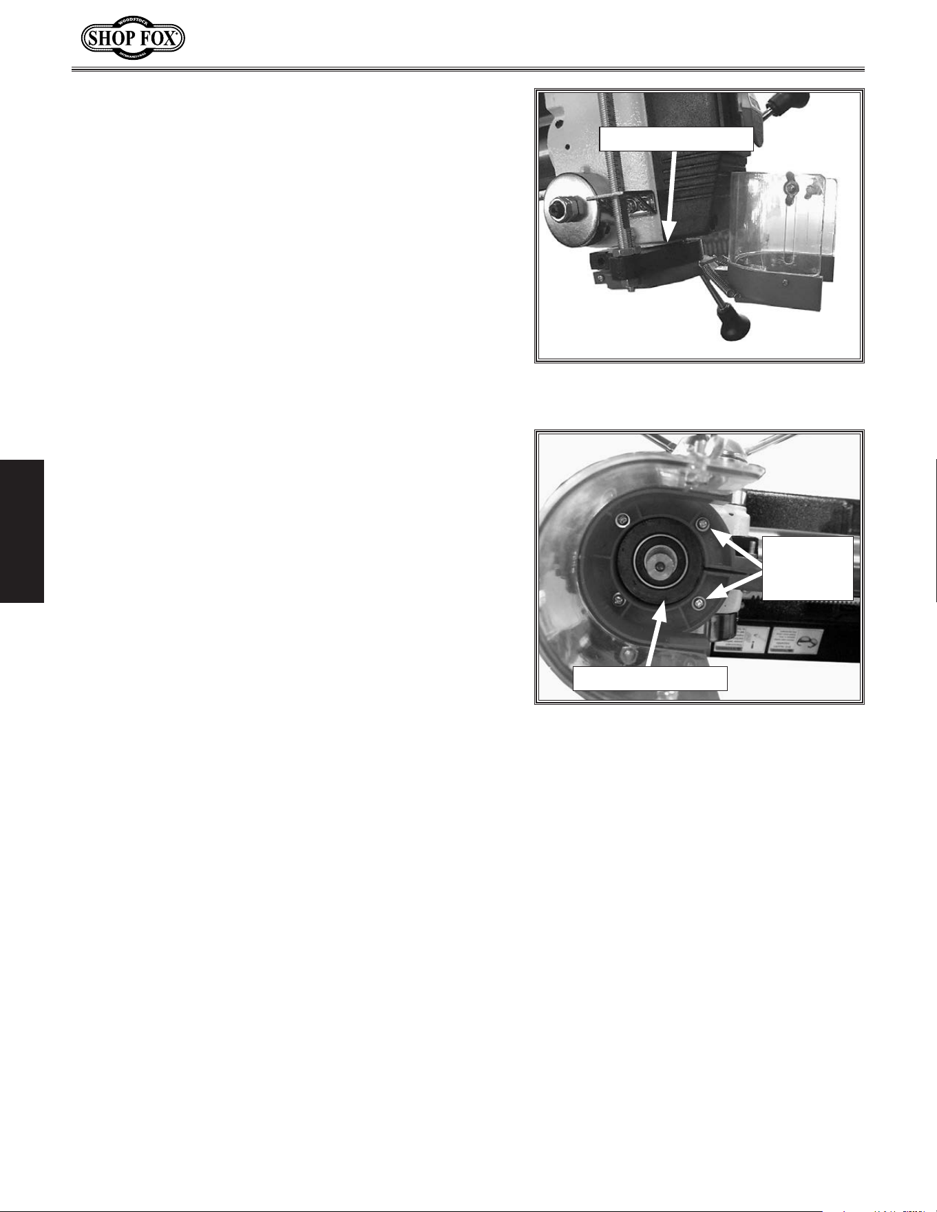
29. Place the drill chuck on the spindle, and
insert the
capscrew into the hole of the
drill chuck, as shown in Figure.20..
30. Tighten the screw so the drill chuck is seat-
ed securely on the spindle.
• If the chuck fails to remain secure on the
spindle, repeat Step 1,.DO.NOT.use.a.
hammer.to.seat.the.drill.chuck.onto.the.
spindle!
-22-
Model W1668/W1848 (Mfd. Since 08/16)
SETUP
34. Secure chuck guard to bracket with four M4-.7 x 10
Phillips head screws and 4mm flat washers, as shown
in Figure. 23.
33.. Slide chuck guard onto bottom of depth stop brack-
et, as shown in Figure.22.
Figure.22. Chuck guard installed on depth
stop bracket.
Depth Stop Bracket
Figure.23. Chuck guard secured to depth
stop bracket.
Depth Stop Bracket
Screws
& Washers
(2 of 4)
-23-
Model W1668/W1848 (Mfd. Since 08/16)
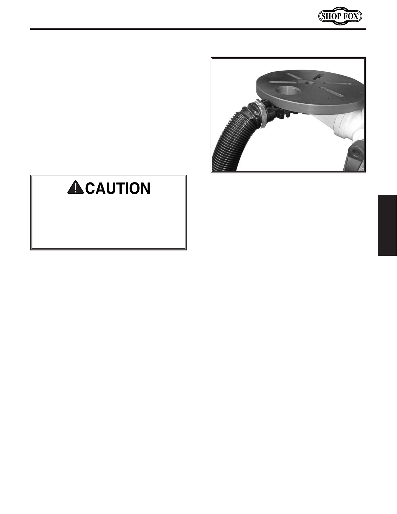
SETUP
Figure.24. Dust port connected to dust
collection system.
To connect hose, do these steps:
1. Fit a 2" dust hose over the dust port, as
shown in Figure.24, and secure it in place
with a hose clamp.
2. Tug the hose to make sure it does not come
off.
Note: A tight fit is necessary for proper
performance.
Dust.Collection
This.machine.creates.substantial.amounts.of.
dust. during. operation.. Breathing. airborne.
dust.on.a.regular.basis.can.result.in.perma-
nent.respiratory.illness..Reduce.your.risk.by.
wearing.a.respirator.and.capturing.the.dust.
with.a.dust.collection.system.
Recommended. CFM.at.Dust.Port.......... 150.CFM
Tools Needed Qty
Dust Collection System ............................. 1
Dust Hose 2" ......................................... 1
Hose Clamps 2" ...................................... 2
Do not confuse this CFM recommendation with
the rating of the dust collector. To determine
the CFM at the dust port, you must consider
these variables: (1) CFM rating of the dust col-
lector, (2) hose type and length between the
dust collector and the machine, (3) number of
branches or wyes, and (4) amount of other open
lines throughout the system. Explaining how to
calculate these variables is beyond the scope
of this manual. Consult an expert or purchase a
good dust collection “how-to” book.
-24-
Model W1668/W1848 (Mfd. Since 08/16)
SETUP
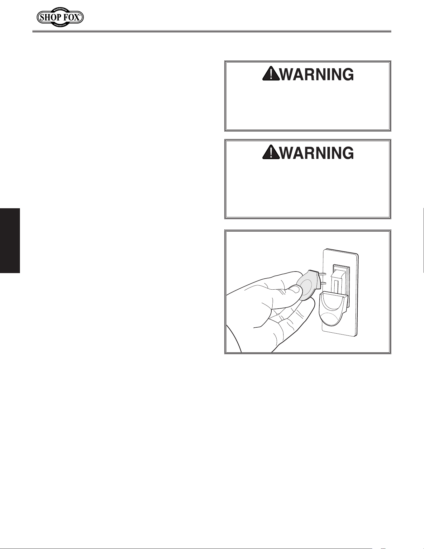
Figure.25. Removing switch key from paddle
switch.
Test. Run
To.test.run.the.machine,.do.these.steps:
1. Clear all setup tools away from machine.
2. Connect machine to power supply.
3. Turn machine ON, verify motor operation,
then turn machine OFF.
The motor should run smoothly and without
unusual noises.
4. Remove switch disabling key (see example).
5. Try to start machine with paddle switch.
The machine should not start.
— If machine does not start, the switch dis-
abling feature is working as designed.
— If machine does start, immediately stop
the machine. The switch disabling fea-
ture is not working correctly. This safety
feature must work properly before pro-
ceeding with regular operations. Call
Tech Support for help.
Serious.injury.or.death.can.result.from.using.
this.machine.BEFORE.understanding.its.con-
trols.and.related.safety.information..DO.NOT.
operate,.or.allow.others.to.operate,.machine.
until. the.information.is.understood.
DO. NOT. start. machine. until. all. preceding.
setup. instructions. have. been. performed..
Operating. an. improperly. set. up. machine.
may. result. in. malfunction. or. unexpected.
results. that. can. lead. to. serious. injury,.
death,.or.machine/propert y.damage..
Once assembly is complete, test run the
machine to ensure it is properly connected to
power and safety components are functioning
properly.
If you find an unusual problem during the test
run, immediately stop the machine, disconnect it
from power, and fix the problem BEFORE oper-
ating the machine again. The Troubleshooting
table in the SERVICE section of this manual can
help.

-25-
Model W1668/W1848 (Mfd. Since 08/16)
SETUP
Spindle.Break-In
DO NOT perform this procedure indepen-
dently of the Test Run section. The drill
press could be seriously damaged if the con-
trols are set differently than instructed in
that section.
Complete the spindle bearing break-in pro-
cedure to prevent rapid wear and tear of
spindle components once the drill press is
placed into operation.
To.perform.spindle.break-in:
1. Make sure machine has been properly lubri-
cated. Refer to Lubrication on Page 38.
2. Make sure spindle area is free of obstruc-
tions.
3. Set spindle speed to the lowest RPM. Refer
to Adjusting Drill Speed on Page 31.
4. Run spindle for 10 minutes at the slow-
est speeds, 5 minutes at each speed listed
below, in progressive order.
a. 250 RPM
b. 640 RPM
c. 1530 RPM
d. 1870 RPM
e. 3050 RPM
5. Turn machine OFF.
Congratulations! Spindle break-in is now complete.
The spindle break-in procedure distributes lubri-
cation throughout the bearings to reduce the
risk of early bearing failure if there are any "dry"
spots or areas where lubrication has settled in
the bearings. You must complete this procedure
before placing operational loads on the spindle
for the first time when the machine is new or if
it has been sitting idle for longer than 6 months.
Always start the spindle break-in at the lowest
speed to minimize wear if there are dry spots.
Allow the spindle to run long enough to warm up
and distribute the bearing grease, then incremen-
tally increase spindle speeds and repeat this pro-
cess at each speed until reaching the maximum
spindle speed. Following the break-in procedure
in this progressive manner helps minimize any
potential wear that could occur before lubrication
is fully distributed.
-26-
Model W1668/W1848 (Mfd. Since 08/16)
OPERATIONS
OPERATIONS
To.complete.typical.operation,.operator.does.following:.
1. Examines workpiece to make sure it is suitable for
drilling.
2. Puts on required safety glasses and face shield.
3. Firmly secures workpiece to table using a vise or
T-slot clamps.
4. Installs correct cutting tool for operation.
5. Adjusts table to correct height, then locks it in
place.
6. Selects appropriate spindle speed according to V-belt
configuration chart located inside belt cover.
7. Connects machine to power, and starts spindle rota-
tion in proper direction for cutting tool installed.
8. Begins drilling.
9. When finished, stops spindle rotation and discon-
nects machine from power.
General
This machine will perform many types of operations
that are beyond the scope of this manual. Many of these
operations can be dangerous or deadly if performed
incorrectly.
The instructions in this section are written with the
understanding that the operator has the necessary
knowledge and skills to operate this machine. If at any
time you are experiencing difficulties performing any
operation, stop using the machine!
The overview below provides the novice machine operator
with a basic understanding of how the machine is used
during operation, so the machine controls/components
discussed later in this manual are easier to understand.
Due to its generic nature, this overview is
NOT intended
to be an instructional guide.
To. reduce. your. risk. of. serious. injury.
or. damage. to. the. machine,. read. this.
entire.manual.BEFORE.using.machine.
To. reduce. the. r isk. of. eye. injury. and.
long-term. respiratory. damage,. always.
wear. safety. glasses. and. a. respirator.
while.operating.this.machine.
If you are an inexperienced operator,
we strongly recommend that you read
books or trade articles, or seek training
from an experienced operator of this
type of machinery before performing
unfamiliar operations. Above.all,.safety.
must.come.first!
-27-
Model W1668/W1848 (Mfd. Since 08/16)
ADJUSTMENTS
The drill press main drive belts last a long
time; however, during machine life, a belt may
stretch slightly, which can cause the pulleys to
slip under load. You will then need to adjust
the motor-to-idler pulley belt tension to com-
pensate for this normal stretching.
NOTE:.The spindle-to-idler pulley belt automati-
cally adjusts to the correct tension when the
motor-to-idler pulley belt tension is adjusted.
NOTICE
The.oscillator.belt.is.not.adjustable..If.the.
belt.shows.cracks.or.is.slipping,.replace.the.
belt.with.a.new.one.
MAKE.SURE.your.machine.is.
unplugged. during. all.
assembly,. adjustments,. or.
maintenance. procedures..
Otherwise.serious. personal.
injury.may.occur!
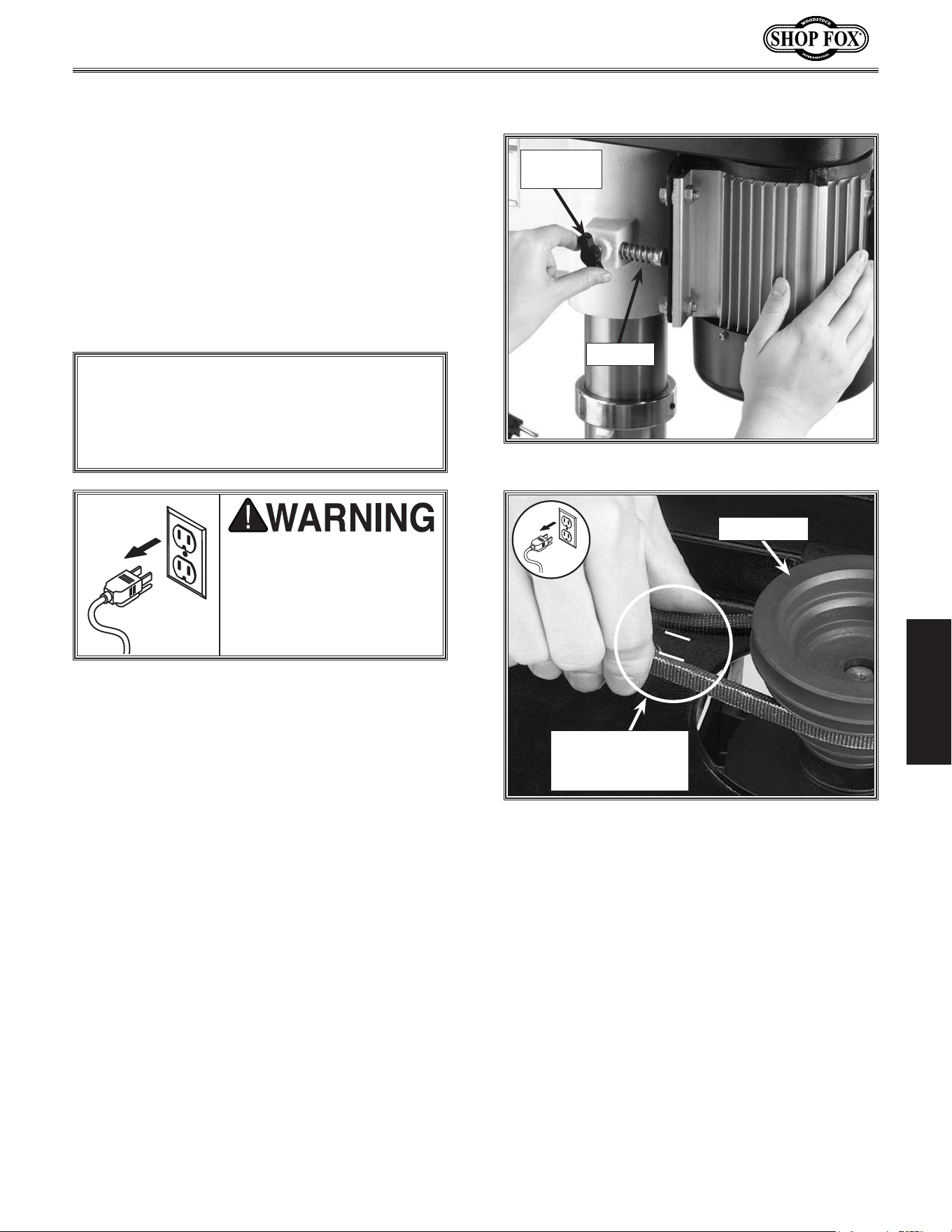
Figure.26..Motor lock screw.
Motor.Lock.
Screw
Push.Rod
Figure.27..Measuring belt deflection.
Belt.Deflection.Gap.
Should.Be.About.
1
1
⁄2"
Motor.Pulley
Tensioning.Belt
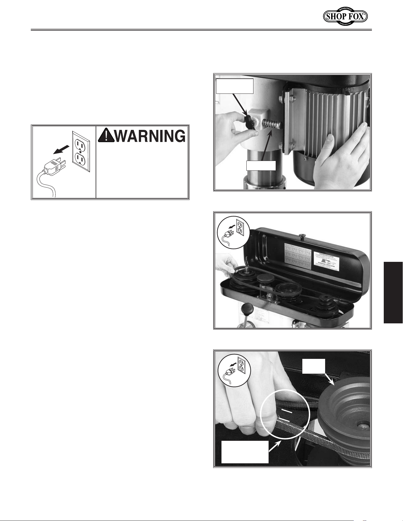
To.adjust.the.drive.belt.tension,.do.these.
steps:
1... DISCONNECT THE MACHINE FROM POWER!.
2... Open the belt cover.
3.. Loosen the motor lock screw at the side of
the headstock, as shown in Figure.26.
4... Gently pivot the motor away from the push
rod rubber until the belt is tight.
5... Hold the motor in position so the rubber
pad is held against the motor.
6... Tighten the lock screw, and make sure the
belt deflection gap is correct when pinched
together between the pulleys (see Figure.
27).
• If the gap between both inner sides of the
belt is greater or less than 1
1
⁄2", repeat
Steps.3 through 6 until the deflection gap
is 1
1
⁄2".
-28-
Model W1668/W1848 (Mfd. Since 08/16)
ADJUSTMENTS
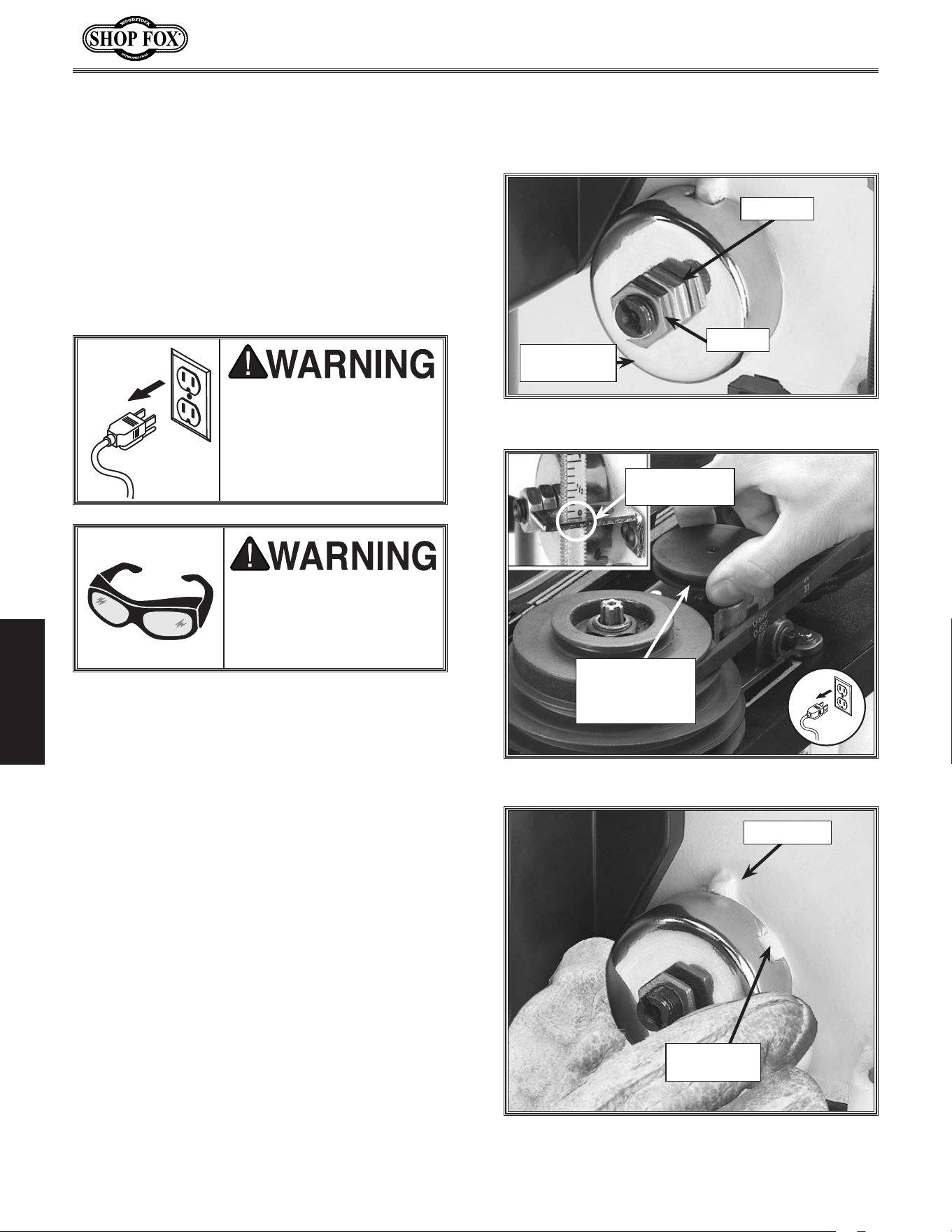
1... DISCONNECT THE MACHINE FROM POWER!
2... Wipe off any oil on the spring lock cover so
it will not slip in your fingers when you hold
the cover from spinning (see Figure.28).
3... Rotate the oscillator pulley so the depth stop
reads “0” and the quill shaft is completely
seated, as shown in Figure.29.
4... Put on thick leather gloves and hold the
spring cover against the side of the head-
stock, so the cover stays splined with the
locking lug, and remove the jam nut to
loosen the cover nut approximately
1
⁄4"
(6.4mm).
5... Pull the cover outward just enough to dis-
engage the spring-cover lock slot from the
locking lug (see Figure.30).
6... Rotate the cover counterclockwise to
increase spring tension, or let the cover
slowly unwind in the clockwise direction to
reduce spring tension (see Figure.30).
MAKE.SURE.your.machine.is.
unplugged. during. all.
assembly,. adjustments,. or.
maintenance. procedures..
Otherwise.serious. personal.
injury.may.occur!
WEAR.safety.glasses.when.
adjusting.springs..Serious.
injury. may. occur. if. this.
warning.is.ignored!
Figure.28..Typical feed shaft return spring assy.
Spring.Lock.
Cover
Cover.Nut
Jam.Nut
Tensioning.Feed.
Shaft.Spring
Figure.30. Typical spring cover lock slot and
locking lug.
Spring-Cover.
Lock.Slot
Locking.Lug
Figure.29..Fully seating quill shaft.
Depth.Stop.
Reads.“0”
Rotate.Oscillator.
Pulley.Until
Depth.Stop.
Reads.Zero.
The feed shaft return spring is adjusted at the
factory; however, during the life of the drill
press you may want to adjust the feed shaft
return spring to a stronger return pressure.
To.adjust.the.feed.shaft.spring.tension,.do.
these.steps:
-29-
Model W1668/W1848 (Mfd. Since 08/16)
ADJUSTMENTS
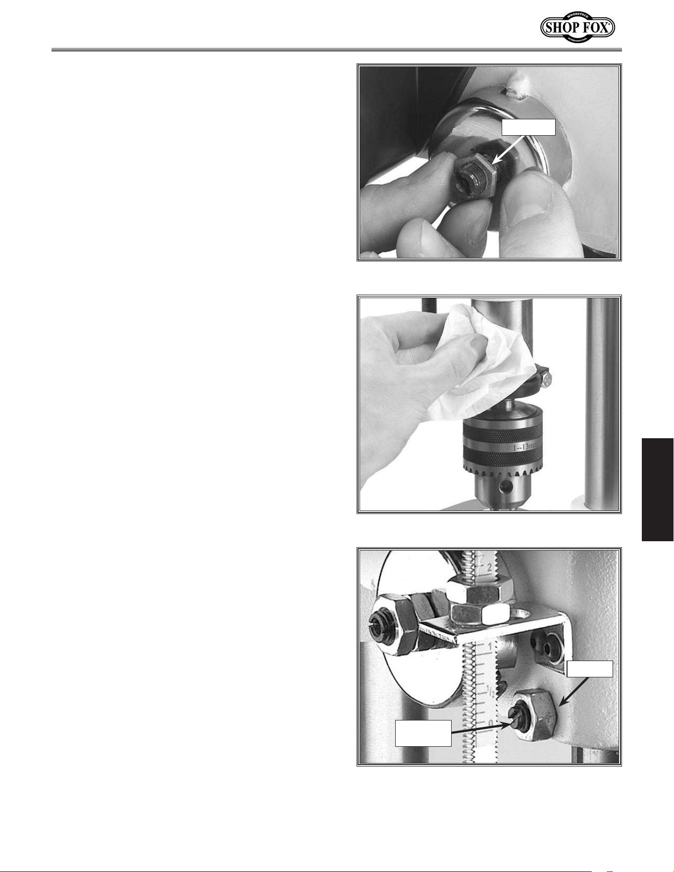
7... Engage the next available spring-cover lock
slot with the locking lug, and hold the
spring lock cover tightly against the side of
the headstock (see Figure.31).
8... Snug the cover nut against the spring cover
just until the nut stops, and then back-off
the nut approximately
1
⁄3 turn, or just
enough so there is no binding anywhere
along complete spindle travel.
9... Hold the cover nut and tighten the jam nut
against the cover nut (see Figure.31).
Figure.31..Hold the spring cover tightly.
Cover.Nut
Figure.32..Clean and oil quill shaft.
Figure.33..Typical quill-shaft screw and
jam nut.
Jam.Nut
Quill.Shaft.
Screw
Adjusting.Quill.Shaft.
Screw
While you may never have to adjust the quill
shaft screw, you should understand its function
and know how to adjust it should you ever need
to remove the quill for cleaning. This screw pre-
vents the quill from rotating during drilling and
sanding procedures, and if adjusted incorrectly,
the quill may have lash or bind.
To.adjust.the.quill -shaft.screw,.do.these.steps:
1... DISCONNECT THE MACHINE FROM POWER!
2... Clean and lubricate the quill shaft with a
thin coat of light oil, and make sure the
quill travels freely (see Figure.32).
3... Loosen the jam nut shown in Figure.33.
4... Turn the quil shaft screw clockwise or coun-
terclockwise to establish free, unbinding
travel while moving the quill up and down
through its entire range of travel.
5... When the quil shaft screw is screwed inward
against the quill as far as the screw can go
without binding the quill, hold the screw
and tighten the jam nut.
6... Recheck for quill binding and looseness
while moving the quill up and down through
its entire range of travel and readjust as
required.
-30-
Model W1668/W1848 (Mfd. Since 08/16)
ADJUSTMENTS
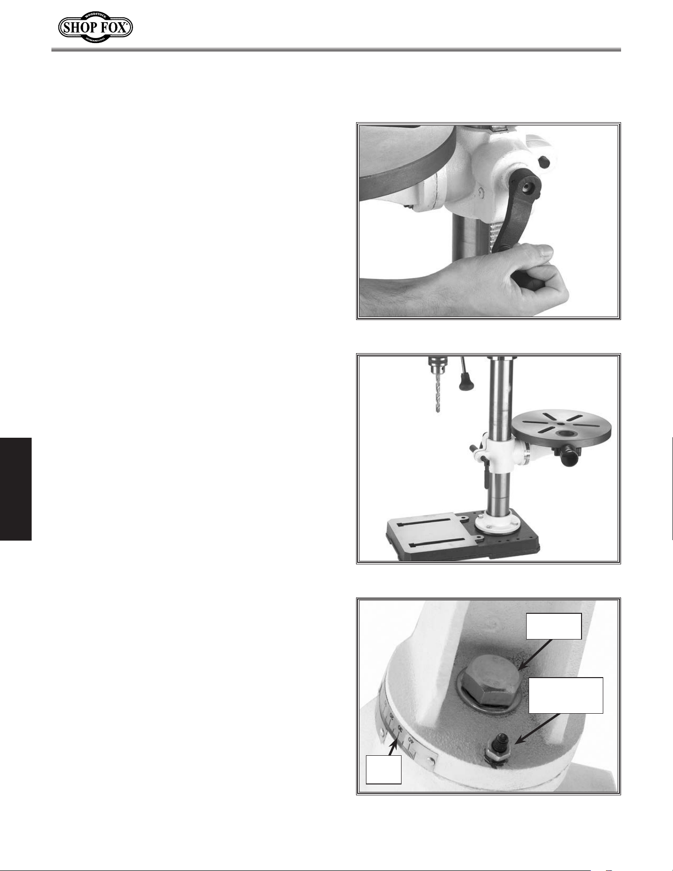
To.adjust.the.table,.do.these.steps:
1... Loosen the table lock lever.
2. Turn the hand crank to raise or lower the
table, as shown in Figure.34.
3... Position the table so the opening in the
installed table insert is centered to the
drill bit or sanding drum.
NOTE: If the table is not needed, pivot
the table to the back side of the column
(Figure.35) so you can support the work-
piece on the base (drilling.operations.
only)..
4... Tighten the table lock lever.
5... Loosen the table tilt lock bolt.
6... Turn the index pin jam nut clockwise and
draw the index pin out of the casting until
you can rotate the table to your desired
angle, and use the tilt scale to find your
desired drilling or sanding angle (see Figure.
36).
NOTE: Use this index pin only for indexing
the table in the “Zero degree” position.
(To index the table back to the zero posi-
tion, turn the table to zero, tap the index
pin back into the casting, snug the index
pin jam nut, and tighten the table tilt lock
bolt.)
7... Tighten the tilt table lock bolt, and double
check your angle.
Figure.34..Raise or lower the table.
Figure.35..Table adjusted behind column.
Adjusting.Table.
Height.&.Tilt
Figure.36..Table tilt lock bolt.
Table.Tilt.
Lock.Bolt
Index.Pin.and.
Index.Pin.Jam.
Nut
Tilt.
Scale
You can adjust the table height and tilt to
accommodate for workpiece height or achieve
special drilling/sanding angles. You can also
move the table out of the way and use the drill
press base as a table for drilling/sanding.
-31-
Model W1668/W1848 (Mfd. Since 08/16)
ADJUSTMENTS
To.change.the.drilling.speed,.do.these.steps:
1... DISCONNECT THE MACHINE FROM POWER!
2.. Refer to the speed chart located under the
belt cover or refer to the "Drill.Press.
Speed".chart on Page. 33, and choose the
desired speed.
3... Loosen the motor lock screw (see.Figure.
37).
4. Pull the motor toward the front of the drill
press to remove tension from the V-belt.
5.. Move the V-belt to the desired V-grooves on
the motor and spindle pulleys (see Figure.
38).
6.. Push the motor toward the back of the
headstock; the push rod is spring loaded
and will follow the motor (see Figure.37)..
7... Tighten the lock screw, and make sure the
belt deflection is 1
1
⁄2" between both inner
sides when the belt is pinched together
between the pulleys, as shown in Figure.
39..Refer to “Belt Tension” in the
ADJUSTMENTS section on Page.15.forde-
tails.
8. Close the cover. The.motor. will.not.start.
until.the.cover.is.closed.
UNPLUG. the. drill. press.
before. changing. speeds.
to. avoid. accidental. start.
up..Failure.to.do.this.may.
result.in.serious.personal.
injury.
The Model W1668 13-
1
⁄4'' Oscillating Drill Press
has 12 speeds ranging from 250 to 3050 RPM.
Refer to the speed charts located under the
belt guard while following the instructions
below.
Figure.38..Adjusting belt to desired speed.
Changing.Spindle.
Speeds
Figure.39..Measuring belt deflection.
Motor.
Pulley
Belt.Deflection.
gap.should.be.
about.
1
1
⁄2"
Figure.37..Loosening the lock knob.
Motor.Lock.
Screw
Push.Rod
-32-
Model W1668/W1848 (Mfd. Since 08/16)
ADJUSTMENTS
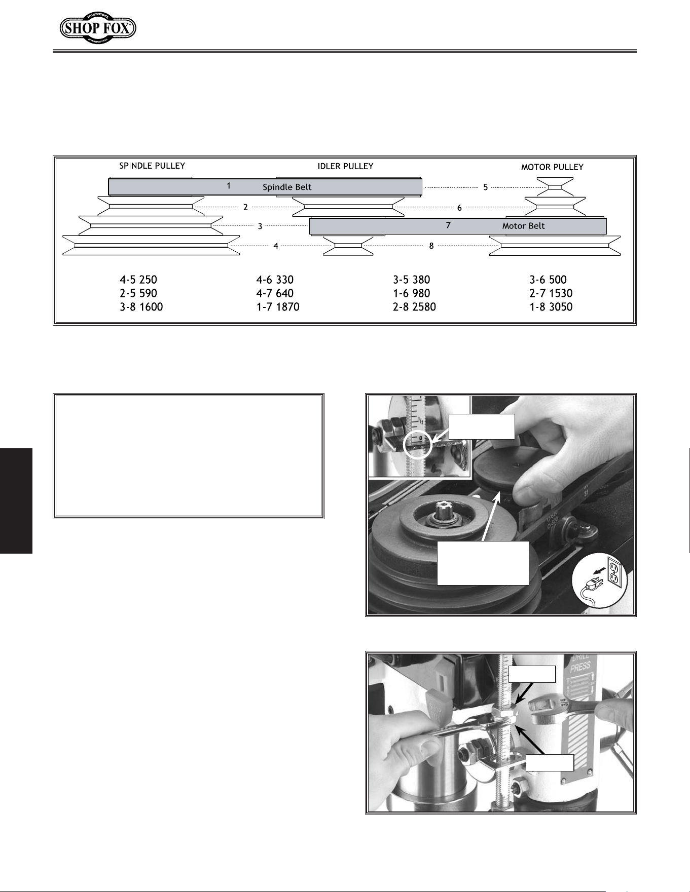
Figure.40..Drill Press Speed Chart.
Drill.Press.Speed .Chart
Your new drill press comes fitted with a depth
stop that allows drilling holes at a preset depth.
To.adjust.the.drilling.depth,.do.these.steps:
1.. DISCONNECT THE MACHINE FROM POWER!
2. Rotate the oscillator pulley until the depth
stop reads “0” (see Figure.41).
3. Loosen the jam nut on the depth stop rod
(see Figure. 42).
4. Turn the stop nut to the desired depth as
indicated by the depth stop scale (see.
Figure.42).
5. Tighten the jam nut against the stop nut
while making sure the stop nut stays in position.
6. To make sure the depth has been set cor-
rectly, drill a hole into scrap stock before
drilling into any workpiece, and readjust
the depth stop if necessary.
Adjusting.Depth.Stop
NOTICE
BACK-OFF. the. depth. stop. completely. and.
secure.the.stop.nuts.before.using.the.oscillat-
ing.feature..If. the.depth.stop.is.left.adjusted.
for.a.shallow.hole,.or.the.nuts.rattle.down.to.
the. stop. while. in. operation,. the. depth. stop.
will.bottom.out.and.break.the.oscillator.
Figure 42. Actual stop depth being measured.
Jam.Nut
Stop.Nut
Rotate.Oscillator.
Pulley.Until
Depth.Stop.Reads.
Zero.
Depth.Stop.
Reads.“0”
Figure.41. Retracting the oscillator for drilling.
Use Figure. 38.to select the optimum motor-to-spindle pulley ratio for drilling, cutting, and sanding
operations. The belt setting in the example in Figure. 40 shows the spindle belt in the #1 spindle pulley
position and the motor belt in the #7 motor pulley location. This will produce a speed of 1,870 RPM.
-33-
Model W1668/W1848 (Mfd. Since 08/16)
ADJUSTMENTS
Calculating.Spindle.Speed.for .Drilling
Using.the.Drill.Bit.Speed.Chart
The chart shown in Figure.43 is intended as a
guide only. Always follow the manufacturer's
speed recommendations if provided with your
drill bits, cutters, or hole saws. Exceeding the
recommended speeds may be dangerous to the
operator.
The speeds shown here are intended to get you
started. The optimum speed will always depend
on various factors, including tool diameter, drill-
ing pressure, material hardness, material quality,
and desired finish.
Often, when drilling materials other than wood,
some type of lubrication is necessary.
Lubrication Suggestions
Wood ............................................. None
Plastics .................................. Soapy Water
Brass ........................ Water-Based Lubricant
Aluminum ................. Paraffin-Based Lubricant
Mild Steel .......................Oil-Based Lubricant
Larger.bits.turning.at.slower.spe eds.tend.to.
grab.the.workpiece.aggressively..This.can.
result.in.the.operator's.hand.being.pulled.
into.the.bit.or.the.workpiece.being.thrown.
with.great.force..Always.clamp.the.work-
piece.to.the.table.to.prevent.injuries.
Twist/Brad Point Drill Bits Soft Wood Hard Wood Plastic Brass Aluminum Mild Steel
1/16" – 3/16" 3000 2500 2500 2500 3000 2500
13/64" – 3/8" 2000 1500 2000 1250 2500 1250
25/64" – 5/8" 1500 750 1500 750 1500 600
11/16" – 1" 750 500 1000 400 1000 350
S
pade/Forstner Bits Soft Wood Hard Wood Plastic Brass Aluminum Mild Steel
1/4" – 1/2" 2000 1500
9/16" – 1" 1500 1250
1-1/8" – 1-7/8" 1000 750
2–3" 500 350
H
ole Saws Soft Wood Hard Wood Plastic Brass Aluminum Mild Steel
1/2" – 7/8" 500 500 600 600 600 500
1" – 1-7/8" 400 400 500 500 500 400
2" – 2-7/8" 300 300 400 400 400 300
3" – 3-7/8" 200 200 300 300 300 200
4" – 5" 100 100 200 200 200 100
R
osette Cutters Soft Wood Hard Wood Plastic Brass Aluminum Mild Steel
Carbide Insert Type 350 250
One-Piece Type 1800 500
T
enon/Plug Cutters Soft Wood Hard Wood Plastic Brass Aluminum Mild Steel
3/8" – 1/2" 1200 1000
5/8" – 1" 800 600
Figure.43. Drill bit speed chart.
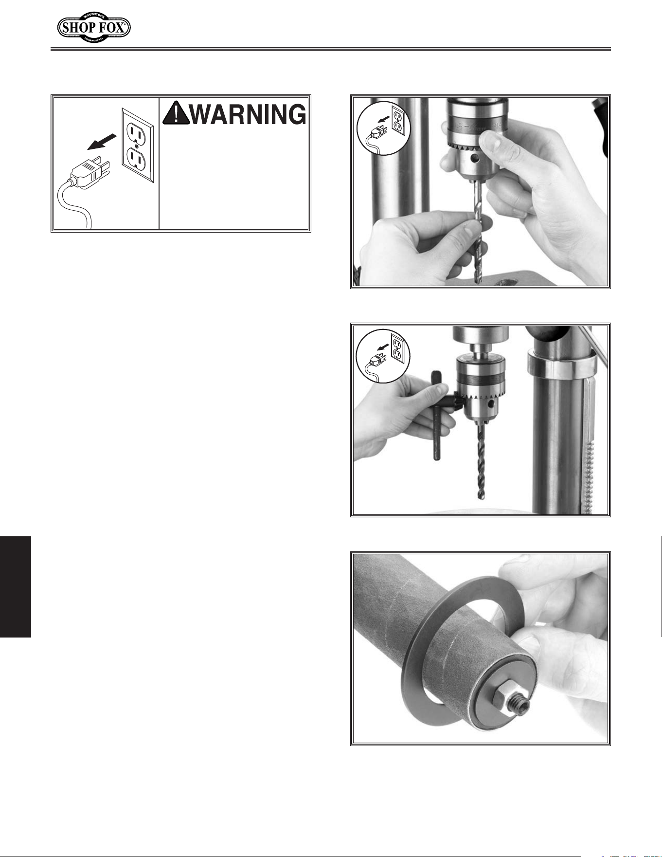
-34-
Model W1668/W1848 (Mfd. Since 08/16)
OPERATIONS
To.change.drill.bits.and.sanding.drums,.do.
these.steps:
1. DISCONNECT THE MACHINE FROM POWER!
2.. Use the chuck key to open the chuck wide
enough to accept the new bit or the sand-
ing drum mandrel (see Figure.44).
3.. Install the bit or mandrel so the chuck jaws
will grab as much of the bit or mandrel
shank as it can.
• If you are installing a small drill bit, make
sure it is held between three jaws instead
of only two, and NEVER allow a chuck to
grab the fluted body of drill bits.
• If you are installing the sanding drum,
install the paper and drum before install-
ing the spindle into the drill chuck (con-
tact your local SHOP FOX
®
dealer for
drums and paper).
4.. Tighten the chuck with the chuck key,
using any of the three key end locations.
(see Figure. 45).
5.. Choose the insert that has an opening
which is approximately
1
⁄4" bigger than the
sanding drum chosen. For drilling, always
use the table insert (see Figure.46) with
the smallest opening. A table insert is not
needed when a 2" drum is used.
6.. Install the chosen table insert into the
pocket in the top of the table.
7.. Remove the chuck key and reconnect the
power source.
8.. Reverse these steps to remove the drill bit
or sanding drum.
NEVER. troubleshoot. or.
adjust.the.machine.while.
it. is. running.. Wait. until.
the.machine.is.turned.off,.
unplugged.and.all.working.
parts.have.come.to.a.stop.
before.proceeding!
Figure.44..Installing bit.
Figure.46..Sanding drum table insert.
Figure.45..Chuck key engaged.
Changing.Drill/Drum
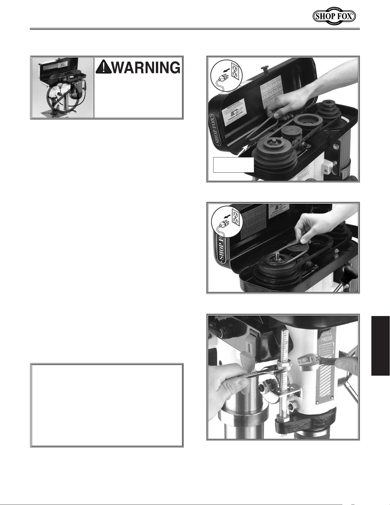
-35-
Model W1668/W1848 (Mfd. Since 08/16)
OPERATIONS
One of the great features of the Model W1668
13
1
⁄4'' Oscillating Drill Press is its sanding capa-
bility. The drill press can be converted from
drilling operations to sanding operations in just
a few steps.
To.use.the.oscillating.feature,.do.these.steps:
1.. DISCONNECT THE MACHINE FROM POWER!
2.. Remove the spindle handles.
3.. Lift the belt cover and remove the round
belt located on the storage bracket under
the speed chart, as shown in Figure.47.
.
4.. Stretch the belt onto the top groove in the
spindle and oscillating pulley, as shown in
Figure.48.
5..
Close the cover. The motor will not start
until the cover is closed.
6.. Loosen the jam nut for the depth stop and
adjust both nuts until they are positioned
at the top of the depth stop rod. Tighten
the jam nut (see Figure.49).
UNPLUG.the.machine.and.
remove.all.handles.before.
using. the. oscillating. fea-
ture.. The. handles. swing .
during.operation.
Figure.49..Back-off the depth stop nuts.
Figure.48..Stretch the belt to fit on pulleys.
Using.the.Oscillator
ALWAYS.back-off.the.depth.stop.completely.
and.secure.the.depth.stop.nuts.before.using.
the.oscillating. feature..If. the.depth. stop.is.
left.adjusted.for.a.shallow.hole,.or.the.nuts.
rattle.down.to.the.stop.while.in.operation,.
the. depth. stop. will. bottom. out. and. break.
the.oscillator.
NOTICE
Figure.47..Oscillator belt on storage bracket.
Belt.and.stor-
age.bracket
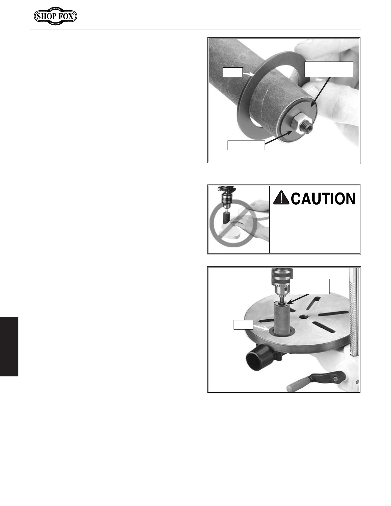
-36-
Model W1668/W1848 (Mfd. Since 08/16)
OPERATIONS
7.. Remove the mandrel nut from the mandrel.
8.. Install the sanding drum, sandpaper, and
top and bottom mandrel washers on the
mandrel, then secure with the mandrel nut,
as shown in Figure.50.
9.. Choose the insert that has an opening
which is slightly bigger than the sanding
drum chosen (see Figure.50).
• For general drill bits, small reamers, and
miscellaneous small cutting and sanding
bits, use the
5
⁄8'' and the 1'' table inserts.
• For the 1'' sanding drum, use the 1
3
⁄8''
table insert.
• For the 1
1
⁄2'' sanding drum, use the 1
7
⁄8''
table insert.
• For the 2'' sanding drum, use no table
insert..
10. Set the chosen table insert into the pocket
in the top of the table, insert the sanding
drum mandrel into the chuck, then tighten
chuck (see Figure.51).
11..Loosen and pivot the table so the opening
in the installed table insert is centered to
the drill bit or sanding drum.
NEVER.sand.or.drill.with-
out.the.table.in.position.
and. the. workpiece.
secured..Serious.person-
al.injury.may.occur.
12..Adjust the table height to use all of the grit
on the paper as the paper wears.
• If the thickness of the workpiece does not
allow much table movement and the sand-
ing drum paper is partially worn on one
end, remove the drum from the sanding
spindle,.turn it end for end and replace it
on the sanding spindle to use the newer
part of the sandpaper.
13..Turn the drill press ON, and begin sanding.
Figure.50..Sanding drum table insert.
Insert
Bottom.Mandrel.
Washer
Mandrel.Nut
Figure.51..Sanding drum installed.
Top.Mandrel.
Washer
Insert

-37-
Model W1668/W1848 (Mfd. Since 08/16)
OPERATIONS
The.4".PRO-STIK
®
.
Stick.with.Handle
is the easiest solution for
increas-
ing the life of sanding sleeves by removing pitch and sawdust particles
from the abrasive pores, which later harden in place if not removed.
Simply press the cleaner lightly against the moving abrasive surface to
remove clogged-up pitch and sawdust.
PRO-STIK
®
cleaners are available
in other sizes for any cleaning application that would need cleaners
with handles, as blocks, or as flat pads. (Not recommended for wide-
belt sanders.)
D2677.Drum.Sander.Set includes three rubber sanding drums 4
1
⁄4"
in length to accommodate 1", 1
1
⁄2" and 2" diameter sanding sleeves.
This kit also includes one 80 grit sleeve for each drum to get things
started.
D2722.Mandrel is a
3
⁄8" shank and is required to use our Drum
Sander Set with any machine. Mandrel is included with the
SHOP FOX
®
Oscillating Drill Presses featured above.
Drill.Press.Clamps
adjust quickly and easily to lock your workpiece
in any position. The clamping pad pivots to conform to any workpiece,
ensuring uniform pressure.
W1301 6" Drill Press Clamp (1
1
⁄2" Capacity)
D2192 10" Drill Press Clamp (3" Capacity)
D2493 12" Drill Press Clamp (5" Capacity)
Sanding. Sleeves are sized to fit the D2677 Drum Sander Set. These
hard Sanding Sleeves are available in 60, 80, 100, 120, and 150 grits.
Keep plenty of these consumable Sanding Sleeves on hand.
Sanding Sleeves
Size
(Dia. x Ht.)
60 Grit 80 Grit 100 Grit 120 Grit 150 Grit
1" X
1
⁄4" D2683 D2684 D2685 D2686 D2687
1
1
⁄2" X
1
⁄4" D2688 D2689 D2690 D2691 D2692
2" X 4
1
⁄4" D2693 D2694 D2695 D2696 D2697
ACCESSORIES
Drill.Press.Accessories
The following Drill Press accessories may be available through your local Woodstock International Inc.
Dealer. If you do not have a dealer in your area, these products are also available through online deal-
ers. Please call or e-mail Woodstock International Inc. Customer Service to get a current listing of deal-
ers at: 1-800-840-8420 or at sales@woodstockint.com.
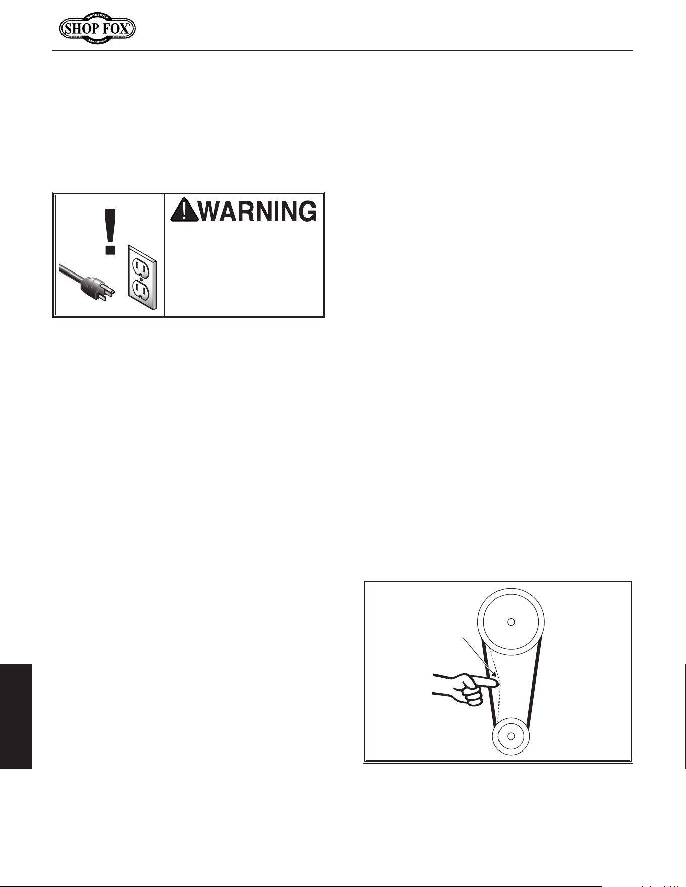
-38-
Model W1668/W1848 (Mfd. Since 08/16)
MAINTENANCE
Keep the table and other unpainted surfaces
rust-free with regular applications of products
like Boeshield
®
T-9. For long term storage con-
sider products like Kleen Bore's Rust Guardit™.
Table.&.Base
MA INTENANCE
As sanding drums are used, the abrasive sleeve
will quickly become "loaded" with sawdust. If
not removed, this sawdust will harden on the
abrasive surface, rendering the sleeve useless.
Routinely clean the sanding sleeve with a rubber
gum abrasive cleaner like the PRO-STIK® clean-
ers, as shown on Page.30.
Always discard worn sanding sleeves. As abrasive
sleeves begin to wear, grit will begin to fall off
and cause gouges in the workpiece. Glue used to
hold the grit to the paper will rub off onto the
workpiece interfering with the final finish.
Sanding.Sleeves
For optimum performance from your machine,
follow this maintenance schedule and refer to
any specific instructions given in this section.
General
Daily.Check
• Make sure drill is disconnected from power
when not in use.
• Check for loose mounting bolts.
• Make sure drill is clean and lubricated.
• Check.for.worn or damaged wires.
• Check for any other unsafe condition.
• Check belts for tension and wear.
Every.90.Days
• Lubricate quill and column racks.
Lubrication
For the quill, table, and column, an occasional
application of light machine oil is all that is
necessary. For the quill and column racks, lubri-
cate with NLGI #2 grease every 90 days. Before
applying lubricant, clean off any dust or metal
chips.
Your goal is to achieve adequate lubrication.
Too much lubrication will attract dirt and dust,
which could cause various parts of your machine
to lose their freedom of movement.
Inspect regularly for tension and wear. Refer to
Figure 52 for proper belt tension. Belt deflec-
tion should be approximately 1-
1
⁄2" under moder-
ate pressure. Check pulleys to ensure that they
are properly aligned when installing V-belts.
To replace the V-belts, refer to Adjusting
Drilling Speed on Page 31 to loosen the belts.
Remove them from the pulleys, then install new
V-belts.
In specting/Replacing.
Belts
Always.disconnect.power.
to. the.machine.before.
performing.maintenance..
Failure.to.do. this.may.
result.in.serious.personal.
injury.
Figure 52. Belt tension.
Pulley
Deflection
Pulley
1-
1
⁄2"

-39-
Model W1668/W1848 (Mfd. Since 08/16)
MAINTENANCE
Tro ublesho oting
The following troubleshooting tables cover common problems that may occur with this machine. If you
need replacement parts or additional troubleshooting help, contact our Technical Support.
Note:
Before contacting Tech Support, find the machine serial number and manufacture date, and if
available, your original purchase receipt. This information is required to properly assist you.
Symptom Possible.Cause Possible.Solution
Machine does not
start or a breaker
trips.
1. Switch disabling key removed or at fault.
2. Incorrect power supply voltage or circuit
size.
3. Power supply circuit breaker tripped or
fuse blown.
4. Motor wires connected incorrectly.
5. Wiring open/has high resistance.
6. Start capacitor at fault.
7. Centrifugal switch at fault.
8. Motor at fault.
1. Insert disabling key or replace.
2. Ensure correct power supply voltage and circuit
size.
3. Ensure circuit is sized correctly and free of shorts.
Reset circuit breaker or replace fuse.
4. Correct motor wiring connections (Page.40).
5. Check/xbroken,disconnected,orcorroded
wires.
6. Test/replace.
7. Adjust/replace centrifugal switch if available.
8. Test/repair/replace.
Machine stalls or is
underpowered.
1. Incorrect/dull cutter/bit for task.
2. Feed rate/cutting speed too fast.
3. Belt(s) slipping.
4. Machine undersized for task.
5. Motor overheated.
6. Pulley slipping on shaft.
7. Centrifugal switch at fault.
8. Motor at fault.
1. Use correct cutter/bit.
2. Decrease feed rate/cutting speed (Page.31).
3. Ensure belts are oil free, tension/replace belt(s);
ensure pulleys are aligned (Page.31).
4. Perform operation with different machine.
5. Clean motor, let cool, and reduce workload.
6. Tighten loose pulley; replace broken/missing
parts.
7. Adjust/replace centrifugal switch if available.
8. Test/repair/replace.
Machine has
vibration or noisy
operation.
1. Motor or other drive component loose.
2. V-belt(s) worn or loose.
3. Motor fan rubbing on fan cover.
4. Pulley loose.
5. Motor mount loose/broken.
6. Motor or spindle bearings at fault.
7. Chuck unbalanced or cutter dull.
1. Inspect/replace damaged bolts/nuts, and
retightenwiththreadlockinguid,ifnecessary.
2. Inspect/replace belts with a new matched set
(Page.31).
3. Fix/replace fan cover; replace loose/damaged
fan.
4. Re-align/replace shaft, pulley set screw, and key.
5. Tighten/replace.
6. Test by rotating shaft; rotational grinding/loose
shaft requires bearing replacement.
7. Replace chuck; replace/resharpen cutter.
Motor.&.Electrical
SERVICE

-40-
Model W1668/W1848 (Mfd. Since 08/16)
MAINTENANCE
Symptom Possible.Cause ..Solution
Tool loose/lack of
power in spindle.
1. Tool incorrectly installed in spindle taper.
2. Debris on tool or spindle taper mating
surfaces.
3. Taking too big of a cut.
4. V-belts are loose.
5. Wrong voltage.
1. Remove and re-install (Page 34).
2. Clean tool and spindle taper.
3. Lessen depth of cut and allow chips to clear (Page
32).
4. Properly tension V-belts (Page 38).
5. Correct voltage.
Workpiece or tool
vibrates or chatters
during operation.
1. Table locks not tight.
2. Workpiece not secure.
3. Spindle speed/feed rate is too fast.
4. Spindle or quill extended too far down.
5. Quill shaft screw not tight.
1. Tighten table locks (Page 30).
2. Properly clamp workpiece on table or in vise.
3. Set spindle speed correctly (Page 31) or use
slower feed rate.
4. Fully retract spindle and lower headstock. This
increases rigidity to decrease vibration.
5. Tighten quill shaft screw (Page 29).
Headstock is hard to
raise.
1. Headstock lock nuts at fault.
2. Rack and pinion at fault or jammed with
grime/debris.
1. Loosen/replace lock nuts.
2. Fix/replace broken or loose parts; clean and
lubricate rack and pinion.
Bad surface finish. 1. Spindle speed too fast for workpiece
material.
2. Dull or incorrect cutting tool.
3. Wrong rotation direction of cutting tool.
4. Workpiece not secure.
5. Spindle extended too far down during
operation.
1. Set spindle speed correctly (Page 31).
2. Sharpen cutting tool or select one that better
suits the operation.
3. Check for proper cutting tool rotation.
4. Properly clamp workpiece on table or in vise.
5. Fully retract spindle and lower headstock. This
increases rigidity.
Spindle overheats. 1. Drill operated at high speeds for extended
period.
1. Allow drill to cool.
Spindle does not
return to highest
position.
1. Poorly adjusted return spring.
2. Worn return spring.
1. Increase return spring tension (Page 28).
2. Replace return spring.
Depth stop pro-
ducing inaccurate
results.
1. Depth stop not calibrated. 1. Calibrate depth stop (Page 32).
Drill Press does not
oscillate.
1. Oscillator belt is not installed properly,
broken, slipping or otherwise at fault.
2. Oscillation mechanism is at fault.
1. Replace oscillator belt (Page 31).
2. Remove oscillating mechanism and replace broken
parts.
Drill.Press.Operations

-41-
Model W1668/W1848 (Mfd. Since 08/16)
MAINTENANCE
Electrical.Safety.Instructions
SHOCK.HAZARD. Working on wiring that is
connected to a power source is extremely
dangerous. Touching electrified parts will
result in personal injury including but not
limited to severe burns, electrocution,
or death. Disconnect the power from
the machine before servicing electrical
components!
QUALIFIED.ELECTRICIAN. Due to the inherent
hazards of electricity, only a qualified
electrician should perform wiring tasks on
this machine. If you are not a qualified
electrician, get help from one before
attempting any kind of wiring job.
WIRE.CONNECTIONS. All connections must
be tight to prevent wires from loosening
during machine operation. Double-check all
wires disconnected or connected during any
wiring task to ensure tight connections.
WIRE/COMPONENT.DAMAGE..Damaged wires
or components increase the risk of serious
personal injury, fire, or machine damage. If
you notice that any wires or components are
damaged while performing a wiring task,
replace those wires or components before
completing the task.
MODIFICATIONS. Using aftermarket parts or
modifying the wiring beyond what is shown
in the diagram may lead to unpredictable
results, including serious injury or fire.
MOTOR.WIRING. The motor wiring shown
in these diagrams is current at the time
of printing, but it may not match your
machine. Always use the wiring diagram
inside the motor junction box.
CAPACITORS/INVERTERS. Some capacitors
and power inverters store an electrical
charge for up to 10 minutes after being
disconnected from the power source.
To reduce the risk of being shocked,
wait at least this long before working on
capacitors.
CIRCUIT.REQUIREMENTS. You MUST follow
the requirements at the beginning of this
manual when connecting your machine to a
power source.
EXPERIENCING.DIFFICULTIES. If you are
experiencing difficulties understanding
the information included in this section,
contact our Technical Support at
(360) 734-3482.
The photos and diagrams
included in this section are
best viewed in color. You
can view these pages in
color at www.shopfox.biz.
BLACK
WHITE
GREEN
RED
BLUE
BROWN
GRAY
ORANGE
YELLOW
YELLOW
GREEN
PURPLE
PINK
LIGHT
BLUE
BLUE
WHITE
TUR-
QUOISE
WIRING DIAGRAM COLOR KEY
These pages are current at the time of printing. However, in the spirit of improvement, we may make
changes to the electrical systems of future machines. Compare the manufacture date of your machine to
the one stated in this manual, and study this section carefully.
If there are differences between your machine and what is shown in this section, call Technical Support
at (360) 734-3482
for assistance BEFORE making any changes to the wiring on your machine. An updated
wiring diagram may be available..Note:.Please gather the serial number and manufacture date of your
machine before calling. This information can be found on the main machine label.
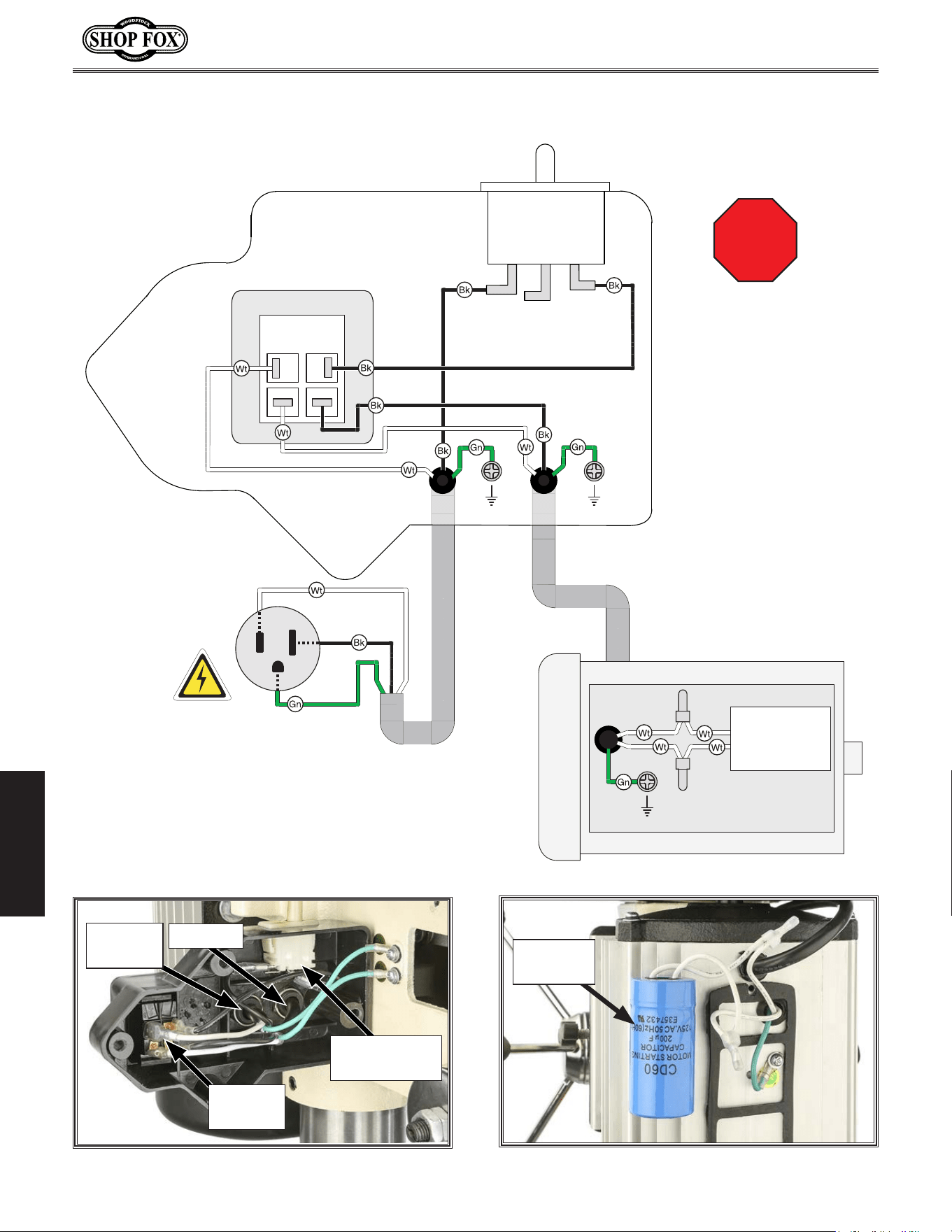
-42-
Model W1668/W1848 (Mfd. Since 08/16)
OPERATIONS
ON/OFF Switch
KEDU HY18
250V 12A
Ground
Ground
110 VAC
5-15 Plug
Neutral
Hot
Ground
110V Motor
Ground
Start Capacitor
200MFD
125V
Pulley Cover
Safety Switch
STOP
Read
Page 61
Before
Wiring
Wiring.Dia gram
Figure.54. Motor start capacitor wiring.
Start
Capacitor
Figure.53. Headstock wiring.
Pulley Cover
Safety Switch
ON/OFF
Switch
To Power
Cord
To Motor
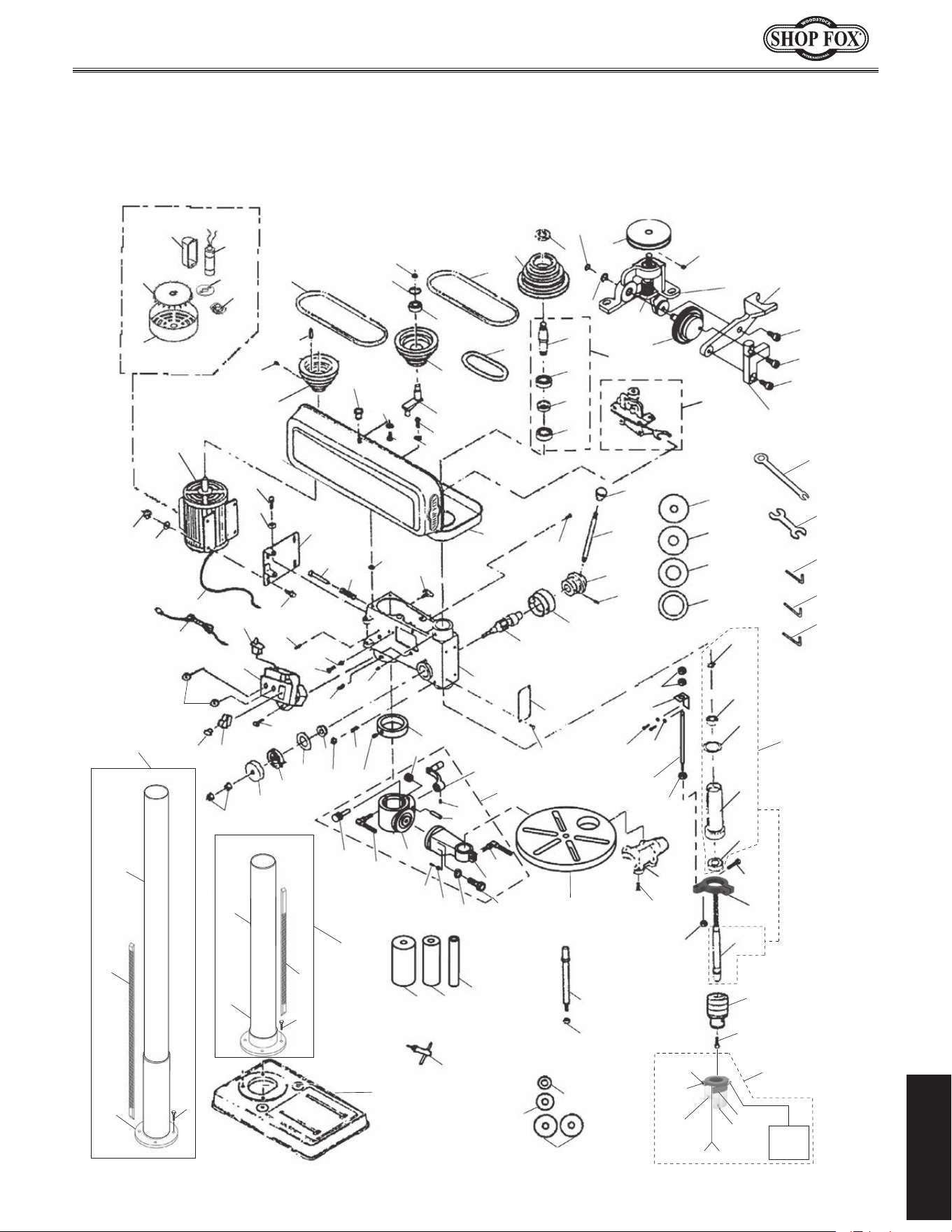
-43-
Model W1668/W1848 (Mfd. Since 08/16)
PARTS
PARTS
Main
1
3
5
6
8
9
12
13
15
16
17
19
20
21
22
23
24
25
26
27
28
29
30
31
32
33
34
35
36
38
39
40
41
42
43
44
45
46
4950
51
52
53
54
55
56
57
58
59
60
61
62
63
64
65
66
67
68
69
70
71
72
73
74
75
76
77
78
79
80
81
82
83
84
85
86
87
89
90
91
92
93
94
95
96
97
98
99
100
102
103
104
105
114
115
116
117
118
135
139
140
141
142
143
144
146
147
148
149
151
152
156
157
23
23
52-1
52-2
52-3
52-4
52-6
52-7
52-8
54
60-1
60-2
60-3
60-4
60-5
60-6
60-7
60-8
60-9
60-10
6317
38
53
88
150
11
112
86A
47
2
7
2
7
3
5
159
159-4
159-5
159-3
159-1
159-2
159-2
159-6 159-7
159-1
W1848
W1668
6

-44-
Model W1668/W1848 (Mfd. Since 08/16)
PARTS
Main.Parts.List
REF PART # DESCRIPTION REF PART # DESCRIPTION
1 X1848001 BASE (W1848) 52-2 X1848052-2 S. CAPACITOR 200M 125V
1 X1668001 BASE (W1668) 52-3 X1848052-3 MOTOR FAN COVER
2 X1848002 COLUMN FLANGE (W1848) 52-4 X1848052-4 WIRING HARNESS
2 X1668002 COLUMN FLANGE (W1668) 52-6 X1848052-6 CAPACITOR COVER
3 X1848003 COLUMN (W1848) 52-7 X1848052-7 CENTRIFUGAL SWITCH
3 X1668003 COLUMN (W1668) 52-8 X1848052-8 CONTACT PLATE
5 X1848005 COLUMN & COLUMN FLANGE ASSY (W1848) 53 X1848053 HEX NUT M8-1.25
5 X1668005 COLUMN & COLUMN FLANGE ASSY (W1668) 54 X1848054 FLAT WASHER 8MM
6 X1848006 HEX BOLT M10-1.5 X 35 (W1848) 55 X1848055 HEX BOLT M8-1.25 X 25
6 X1668006 HEX BOLT M10-1.5 X 25 (W1668) 56 X1848056 HEX BOLT M8-1.25 X 20
7 X1848007 RACK 31-1/2" (W1848) 57 X1848057 PUSH ROD
7 X1668007 RACK 16-15/16 (W1668) 58 X1848058 SPRING
8 X1848008 COLUMN RING 59 X1848059 RUBBER WASHER
9 X1848009 SET SCREW M6-1 X 10 60 X1848060 OSCILLATING MECHANISM
11 X1848011 TABLE 60-1 X1848060-1 PLASTIC GEAR
12 X1848012 WORM PINION 60-2 X1848060-2 OSCILLATING MECHANISM ARM
13 X1848013 CLAMP BOLT M12-1.75 X 50 60-3 X1848060-3 PULLEY
15 X1848015 WORM GEAR 60-4 X1848060-4 WORM GEAR
16 X1848016 LIFT HANDLE 60-5 X1848060-5 DRIVE ARM
17 X1848017 SET SCREW M6-1 X 10 60-6 X1848060-6 BODY
19 X1848019 CLAMP BOLT M10-1.5 X 30 60-7 X1848060-7 OSC. MECH ARM BOLT M6-1 X 20
20 X1848020 DUST PORT 2" 60-8 X1848060-8 CAP SCREW M5-.8 X 15
21 X1848021 PHLP HD SCR M4-.7 X 22 60-9 X1848060-9 CAP SCREW M5-.8 X 15
22 X1848022 HEAD CASTING 60-10 X1848060-10 SET SCREW M6-1 X 6
23 X1848023 HEX NUT M10-1.5 61 X1848061 OSCILLATOR BELT
24 X1848024 SPRING COVER 62 X1848062 PULLEY COVER
25 X1848025 RETURN SPRING 63 X1848063 BALL BEARING 6203-2RS
26 X1848026 SPRING WASHER 10MM 64 X1848064 COLLAR
27 X1848027 BUSHING 65 X1848065 INTERNAL SPLINE SLEEVE
28 X1848028 HEX NUT M8-1.25 66 X1848066 SPLINE SLEEVE ASSY
29 X1848029 SET SCREW M8-1.25 X 25 DOG-PT 67 X1848067 MOTOR MOUNT
30 X1848030 FEED SHAFT 68 X1848068 LOCK NUT M18-1.5
31 X1848031 DEPTH COLLAR 69 X1848069 SPINDLE PULLEY
32 X1848032 ROLL PIN 6 X 20MM 70 X1848070 PHLP HD SCR M6-1.0 X 20
33 X1848033 FEED COLLAR 71 X1848071 LOCK WASHER 6MM
34 X1848034 HANDLE BAR M10-1.5, 155L 72 X1848072 PHLP HD SCR M5-0.8 X 10
35 X1848035 KNOB M10-1.5 73 X1848073 FLAT WASHER 5MM
36 X1848036 LOCK KNOB M8-1.25 74 X1848074 KNOB
38 X1848038 RIVET 75 X1848075 MOTOR PULLEY
39 X1848039 SET SCREW M8-1.25 X 10 76 X1848076 KEY
40 X1848040 SET SCREW M10-1.5 X 12 77 X1848077 IDLER ARM
41 X1848041 PHLP HD SCR M4-.7 X 10 78 X1848078 IDLER PULLEY
42 X1848042 EXT TOOTH WASHER 4MM 79 X1848079 BALL BEARING 6202-2RS
43 X1848043 ROLL PIN 6 X 20MM 80 X1848080 INT RETAINING RING 35MM
44 X1848044 PHLP HD SCR M4-.7 X 10 81 X1848081 V-BELT M20 3L200
45 X1848045 SWITCH BOX 82 X1848082 V-BELT M26 3L260
46 X1848046 LIMIT SWITCH 83 X1848083 EXT RETAINING RING 11MM
47 X1848047 STRAIN RELIEF THREADED 84 X1848084 BALL BEARING 6201-2RS
49 X1848049 SHOP FOX PADDLE SWITCH 110V 85 X1848085 RUBBER WASHER
50 X1848050 PADDLE SWITCH KEY 86 X1848086 QUILL
51 X1848051 POWER CORD 18G 3W 112" 5-15P 86A X1848086A QUILL ASSY
52 X1848052 MOTOR 3/4HP 110V 1-PH 87 X1848087 BALL BEARING 6202ZZ
52-1 X1848052-1 MOTOR FAN

-45-
Model W1668/W1848 (Mfd. Since 08/16)
PARTS
REF PART # DESCRIPTION REF PART # DESCRIPTION
88 X1848088 SPINDLE, JT33 CHUCK 139 X1848139 FLAT WASHER 8MM
89 X1848089 CHUCK 1-16MM JT33 140 X1848140 EXT RETAINING RING 8MM
90 X1848090 CHUCK KEY 141 X1848141 RUBBER DRUM 2" X 4-1/4"
91 X1848091 CAP SCREW M5-0.8 X 20 142 X1848142 RUBBER DRUM 1-1/2" X 4-1/4"
92 X1848092 HEX NUT M8-1.25 143 X1848143 RUBBER DRUM 1" X 4-1/4"
93 X1848093 MANDREL 144 X1848144 TRAVEL INDICATOR PLATE
94 X1848094 MANDREL WASHER 1-3/4" 146 X1848146 TABLE BRACKET N/S
95 X1848095 MANDREL WASHER 7/8" 147 X1848147 COLUMN SUPPORT N/S
96 X1848096 MANDREL WASHER 5/8" 148 X1848148 HEX BOLT M16-2 X 50
97 X1848097 WRENCH 14MM X 1/2" 149 X1848149 FLAT WASHER 16MM
98 X1848098 3MM HEX WRENCH 150 X1848150 COLUMN SUPPORT PIN
99 X1848099 4MM HEX WRENCH 151 X1848151 HEX NUT M6-1
100 X1848100 5MM HEX WRENCH 152 X1848152 OSCILLATING DRILL PRESS WRENCH
102 X1848102 TABLE INSERT 5/8" I.D. 156 X1848156 TABLE BRACKET ASSY
103 X1848103 TABLE INSERT 1" I.D. 157 X1848157 EXT RETAINING RING 15MM
104 X1848104 TABLE INSERT 1 3/8" I.D. 159 X1848159 CHUCK GUARD ASSY
105 X1848105 TABLE INSERT 1 7/8" I.D. 159-1 X1848159-1 PHLP HD SCR M4-.7 X 30
112 X1848112 DEPTH STOP ROD 159-2 X1848159-2 HEX NUT M4-.7
114 X1848114 DEPTH STOP BRACKET 159-3 X1848159-3 TAP SCREW M2.2 X 4.5
115 X1848115 FLAT WASHER 5MM 159-4 X1848159-4 HEX BOLT M5-.8 X 12
116 X1848116 CAP SCREW M5-0.8 X 12 159-5 X1848159-5 WING NUT M5-.8
117 X1848117 DEPTH STOP MOUNT 159-6 X1848159-6 PHLP HD SCR M4-.7 X 10
118 X1848118 CAP SCREW M8-1.25 X 20 159-7 X1848159-7 FLAT WASHER 4MM
135 X1848135 AXLE
Main.Parts.List.(Cont.)
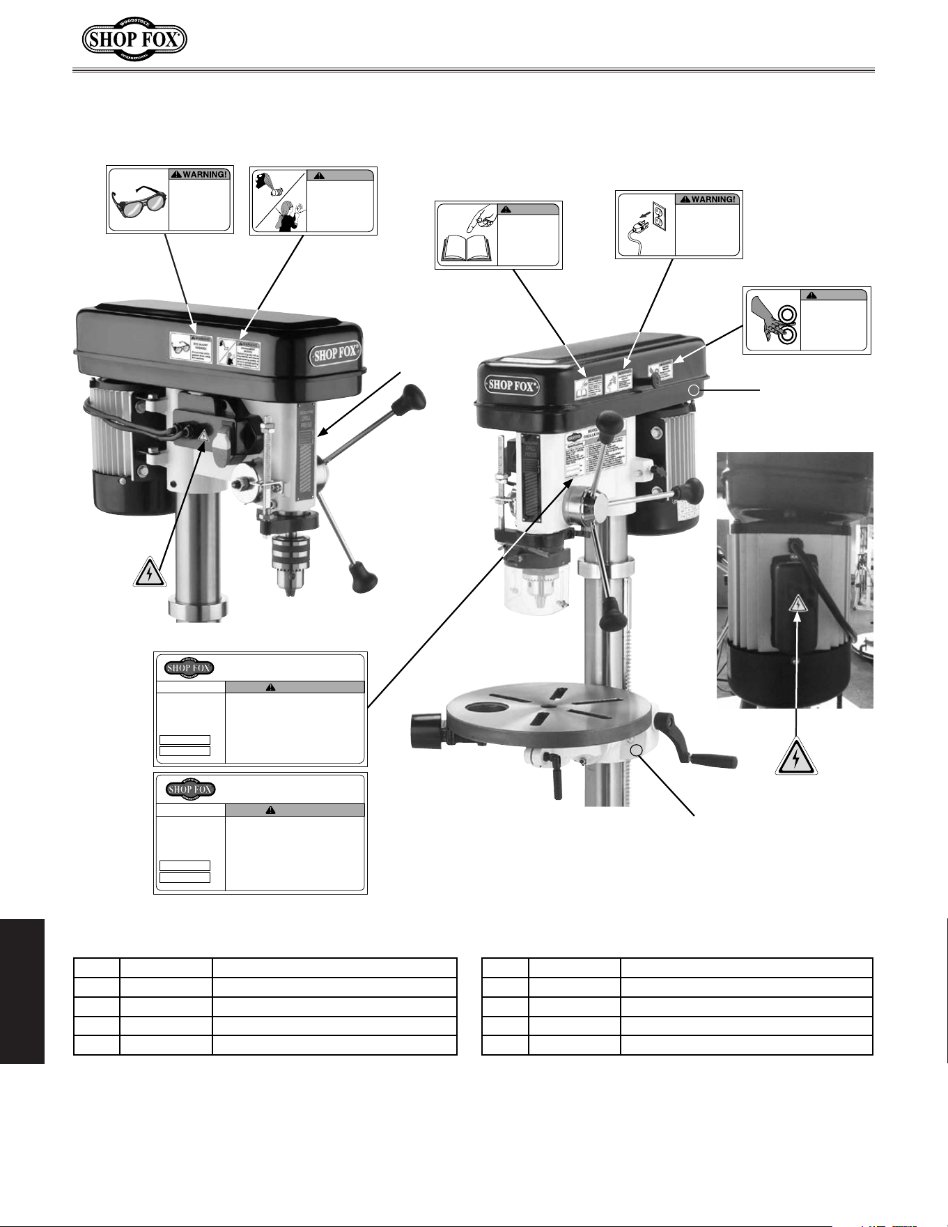
-46-
Model W1668/W1848 (Mfd. Since 08/16)
MAINTENANCE
Labels
Mfd. for Woodstock in China
12. Prevent unauthorized use by children or untrained users.
COLOR CODES
PANTONE 151 C or RAL 2005
WARNING
SF LOGO RED
PANTONE 1795C
SF LOGO YELLOW
PANTONE 600C
COPYRIGHT © WOODSTOCK INTERNATIONAL, INC.
FOR SHOP FOX MACHINES ONLY! DO NOT REPRODUCE OR CHANGE THIS ARTWORK
WITHOUT WRITTEN APPROVAL!
Woodstock will not accept labels changed without
approval. If artwork changes are required, contact us immediately at
WARNING
ENTAGLEMENT
HAZARD!
Tie back long hair, roll up
long sleeves, and remove
loose clothing, jewelry, or
gloves to prevent getting
caught in moving parts.
ACCIDENTAL INJURY
HAZARD!
Disconnect power
supply before
adjustments, setup
or maintenance!
Always keep this
cover closed
during operation.
PINCHING
HAZARD!
WARNING!
READ and UNDERSTAND
MANUAL to avoid serious
injury! If a manual is not
available, DO NOT use
machine! Instead, go to
www.shopfox.biz or call
(
360
)
734-3482.
WARNING!
EYE INJURY
HAZARD!
Always wear safety
glasses when using
this machine.
MODEL W1848 FLOOR-MODEL
OSCILLATING DRILL PRESS
Motor: 3/4 HP, 110V, 60 Hz, 9A
Speeds: 12 (250–3050 RPM)
Swing: 13-1/4"
Spindle Travel: 3-1/8"
Drill Chuck Size: 1–16mm
Oscillating Stroke Length: 3/4"
Weight: 122 lbs.
Specifications
Date
S/N
Mfd. for Woodstock in China
WARNING!
To reduce the risk of serious injury when using this machine:
1. Read and understand owner’s manual before operating.
2. Always wear approved safety glasses.
3. Only plug power cord into a grounded outlet.
4. Disconnect power before setting up or servicing.
5. Tie back long hair, roll up long sleeves, and DO NOT wear loose
clothing, gloves, or jewelry.
6. Keep all guards and covers in place during operation.
7. Clamp or brace workpiece to prevent rotation.
8. Avoid putting hands where they could slip into rotating bits.
9. Always remove chuck keys and other tools before use.
10. Use correct speeds for drill accessories and workpiece.
11. When using as sander, always sand against spindle rotation.
12. Prevent unauthorized use by children or untrained users.
W1848 Machine Labels
(02.14.17)
• Scale= 1:1
(unless otherwise noted)
• Labels MUST be made of
chemical-resistant material
COLOR CODES
WARNING
ENTAGLEMENT
HAZARD!
Tie back long hair, roll up
long sleeves, and remove
loose clothing, jewelry, or
gloves to prevent getting
caught in moving parts.
ACCIDENTAL INJURY
HAZARD!
Disconnect power
supply before
adjustments, setup
or maintenance!
Always keep this
cover closed
during operation.
PINCHING
HAZARD!
WARNING!
EYE INJURY
HAZARD!
Always wear safety
glasses when using
this machine.
Oscillating Stroke Length: 3/4"
Weight: 122 lbs.
Date
S/N
Mfd. for Woodstock in China
5. Tie back long hair, roll up long sleeves, and DO NOT wear loose
clothing, gloves, or jewelry.
6. Keep all guards and covers in place during operation.
7. Clamp or brace workpiece to prevent rotation.
8. Avoid putting hands where they could slip into rotating bits.
9. Always remove chuck keys and other tools before use.
10. Use correct speeds for drill accessories and workpiece.
11. When using as sander, always sand against spindle rotation.
12. Prevent unauthorized use by children or untrained users.
COLOR CODES
PANTONE 151 C or RAL 2005
WARNING
SF LOGO RED
PANTONE 1795C
SF LOGO YELLOW
PANTONE 600C
COPYRIGHT © WOODSTOCK INTERNATIONAL, INC.
FOR SHOP FOX MACHINES ONLY! DO NOT REPRODUCE OR CHANGE THIS ARTWORK
WITHOUT WRITTEN APPROVAL!
Woodstock will not accept labels changed without
approval. If artwork changes are required, contact us immediately at
WARNING
ENTAGLEMENT
HAZARD!
Tie back long hair, roll up
long sleeves, and remove
loose clothing, jewelry, or
gloves to prevent getting
caught in moving parts.
ACCIDENTAL INJURY
HAZARD!
Disconnect power
supply before
adjustments, setup
or maintenance!
Always keep this
cover closed
during operation.
PINCHING
HAZARD!
WARNING!
READ and UNDERSTAND
MANUAL to avoid serious
injury! If a manual is not
available, DO NOT use
machine! Instead, go to
www.shopfox.biz or call
(
360
)
734-3482.
WARNING!
EYE INJURY
HAZARD!
Always wear safety
glasses when using
this machine.
MODEL W1848 FLOOR-MODEL
OSCILLATING DRILL PRESS
To reduce the risk of serious injury when using this machine:
1. Read and understand owner’s manual before operating.
5. Tie back long hair, roll up long sleeves, and DO NOT wear loose
6. Keep all guards and covers in place during operation.
8. Avoid putting hands where they could slip into rotating bits.
9. Always remove chuck keys and other tools before use.
10. Use correct speeds for drill accessories and workpiece.
11. When using as sander, always sand against spindle rotation.
12. Prevent unauthorized use by children or untrained users.
• Scale= 1:1
(unless otherwise noted)
• Labels MUST be made of
chemical-resistant material
COLOR CODES
PANTONE 151 C or RAL 2005
WARNING
SF LOGO RED
PANTONE 1795C
SF LOGO YELLOW
PANTONE 600C
COPYRIGHT © WOODSTOCK INTERNATIONAL, INC.
DO NOT REPRODUCE OR CHANGE THIS ARTWORK
Woodstock will not accept labels changed without
If artwork changes are required, contact us immediately at
WARNING
ENTAGLEMENT
HAZARD!
Tie back long hair, roll up
long sleeves, and remove
loose clothing, jewelry, or
gloves to prevent getting
caught in moving parts.
Always keep this
cover closed
during operation.
PINCHING
HAZARD!
WARNING!
COLOR CODES
PANTONE 151 C or RAL 2005
WARNING
SF LOGO RED
PANTONE 1795C
SF LOGO YELLOW
PANTONE 600C
COPYRIGHT © WOODSTOCK INTERNATIONAL, INC.
FOR SHOP FOX MACHINES ONLY! DO NOT REPRODUCE OR CHANGE THIS ARTWORK
WITHOUT WRITTEN APPROVAL!
Woodstock will not accept labels changed without
approval. If artwork changes are required, contact us immediately at
ACCIDENTAL INJURY
HAZARD!
Disconnect power
supply before
adjustments, setup
or maintenance!
Always keep this
cover closed
during operation.
PINCHING
HAZARD!
READ and UNDERSTAND
MANUAL to avoid serious
injury! If a manual is not
available, DO NOT use
machine! Instead, go to
www.shopfox.biz or call
(
360
)
734-3482.
WARNING!
COLOR CODES
PANTONE 151 C or RAL 2005
WARNING
SF LOGO RED
PANTONE 1795C
SF LOGO YELLOW
PANTONE 600C
COPYRIGHT © WOODSTOCK INTERNATIONAL, INC.
FOR SHOP FOX MACHINES ONLY! DO NOT REPRODUCE OR CHANGE THIS ARTWORK
WITHOUT WRITTEN APPROVAL!
Woodstock will not accept labels changed without
approval. If artwork changes are required, contact us immediately at
Tie back long hair, roll up
long sleeves, and remove
loose clothing, jewelry, or
gloves to prevent getting
caught in moving parts.
ACCIDENTAL INJURY
HAZARD!
Disconnect power
supply before
adjustments, setup
or maintenance!
Always keep this
cover closed
during operation.
PINCHING
HAZARD!
WARNING!
READ and UNDERSTAND
MANUAL to avoid serious
injury! If a manual is not
available, DO NOT use
machine! Instead, go to
www.shopfox.biz or call
(
360
)
734-3482.
WARNING!
HAZARD!
Always wear safety
glasses when using
this machine.
MODEL W1848 FLOOR-MODEL
OSCILLATING DRILL PRESS
Motor: 3/4 HP, 110V, 60 Hz, 9A
Speeds: 12 (250–3050 RPM)
Swing: 13-1/4"
Spindle Travel: 3-1/8"
Drill Chuck Size: 1–16mm
Oscillating Stroke Length: 3/4"
Weight: 122 lbs.
Specifications
Date
S/N
Mfd. for Woodstock in China
WARNING!
To reduce the risk of serious injury when using this machine:
1. Read and understand owner’s manual before operating.
2. Always wear approved safety glasses.
3. Only plug power cord into a grounded outlet.
4. Disconnect power before setting up or servicing.
5. Tie back long hair, roll up long sleeves, and DO NOT wear loose
clothing, gloves, or jewelry.
6. Keep all guards and covers in place during operation.
7. Clamp or brace workpiece to prevent rotation.
8. Avoid putting hands where they could slip into rotating bits.
9. Always remove chuck keys and other tools before use.
10. Use correct speeds for drill accessories and workpiece.
11. When using as sander, always sand against spindle rotation.
12. Prevent unauthorized use by children or untrained users.
W1848 Machine Labels
(02.14.17)
• Scale= 1:1
(unless otherwise noted)
• Labels MUST be made of
chemical-resistant material
COLOR CODES
PANTONE 151 C or RAL 2005
WARNING
SF LOGO RED
PANTONE 1795C
SF LOGO YELLOW
PANTONE 600C
WARNING
ENTAGLEMENT
HAZARD!
Tie back long hair, roll up
long sleeves, and remove
loose clothing, jewelry, or
gloves to prevent getting
caught in moving parts.
ACCIDENTAL INJURY
HAZARD!
Disconnect power
supply before
adjustments, setup
or maintenance!
Always keep this
cover closed
during operation.
PINCHING
HAZARD!
WARNING!
READ and UNDERSTAND
MANUAL to avoid serious
injury! If a manual is not
available, DO NOT use
machine! Instead, go to
www.shopfox.biz or call
(
360
)
734-3482.
WARNING!
EYE INJURY
HAZARD!
Always wear safety
glasses when using
this machine.
160 161
162
163
164
165
166
(W1848)
W1668 Machine Labels
(02.17.17)
• Scale= 1:1
(unless otherwise noted)
• Labels MUST be made of
chemical-resistant material
MODEL W1668 BENCHTOP
OSCILLATING DRILL PRESS
Motor: 3/4 HP, 110V, 60 Hz, 9A
Speeds: 12 (250–3050 RPM)
Swing: 13-1/4"
Spindle Travel: 3-1/8"
Drill Chuck Size: 1–16mm
Oscillating Stroke Length: 3/4"
Weight: 113 lbs.
Specifications
Date
S/N
Mfd. for Woodstock in China
WARNING!
To reduce the risk of serious injury when using this machine:
1. Read and understand owner’s manual before operating.
2. Always wear approved safety glasses.
3. Only plug power cord into a grounded outlet.
4. Disconnect power before setting up or servicing.
5. Tie back long hair, roll up long sleeves, and DO NOT wear loose
clothing, gloves, or jewelry.
6. Keep all guards and covers in place during operation.
7. Clamp or brace workpiece to prevent rotation.
8. Avoid putting hands where they could slip into rotating bits.
9. Always remove chuck keys and other tools before use.
10. Use correct speeds for drill accessories and workpiece.
11. When using as sander, always sand against spindle rotation.
12. Prevent unauthorized use by children or untrained users.
Use Existing
Label
167
168
166
(W1668)
REF PART # DESCRIPTION REF PART # DESCRIPTION
160 X1848160 EYE INJURY HAZARD LABEL 165 X1848165 ELECTRICITY LABEL
161 X1848161 ENTANGLEMENT HAZARD LABEL 166 X1848166 MACHINE ID LABEL (W1848)
162 X1848162 READ MANUAL LABEL 166 X1668166 MACHINE ID LABEL (W1668)
163 X1848163 DISCONNECT POWER LABEL 167 X1848167 TOUCH-UP PAINT, SHOP FOX WHITE
164 X1848164 PINCHING HAZARD LABEL 168 X1848168 TOUCH-UP PAINT, SHOP FOX BLACK


TAPE ALONG EDGES--PLEASE DO NOT STAPLE
FOLD ALONG DOTTED LINE
FOLD ALONG DOTTED LINE
WOODSTOCK.INTERNATIONAL.INC..
P.O..BOX.2309.
BELLINGHAM,.WA.98227-2309
Place
Stamp
Here

WARRANTY
Woodstock International, Inc. warrants all Shop Fox machinery to be free of defects from workmanship
and materials for a period of two years from the date of original purchase by the original owner.
This warranty does not apply to defects due directly or indirectly to misuse, abuse, negligence or
accidents, lack of maintenance, or reimbursement of third party expenses incurred.
Woodstock International, Inc. will repair, replace, or arrange for a dealer refund at its expense and
at its option, the Shop Fox machine or machine part, which in proper and intended use has proven to
be defective, provided that the original owner returns the product prepaid to an authorized warranty
or repair facility as designated by our Bellingham, Washington office with proof of their purchase of
the product within two years, and provides Woodstock International, Inc. reasonable opportunity to
verify the alleged defect through inspection. If it is determined there is no defect, or that the defect
resulted from causes not within the scope of Woodstock International Inc.'s warranty, then the original
owner must bear the cost of storing and returning the product.
This is Woodstock International, Inc.’s sole written warranty and any and all warranties that may be
implied by law, including any merchantability or fitness, for any particular purpose, are hereby limited
to the duration of this written warranty. We do not warrant that Shop Fox machinery complies with
the provisions of any law, acts or electrical codes. We do not reimburse for third party repairs. In no
event shall Woodstock International, Inc.’s liability under this limited warranty exceed the purchase
price paid for the product, and any legal actions brought against Woodstock International, Inc. shall be
tried in the State of Washington, County of Whatcom. We shall in no event be liable for death, injuries
to persons or property or for incidental, contingent, special or consequential damages arising from the
use of our products.
Every effort has been made to ensure that all Shop Fox machinery meets high quality and durability
standards. We reserve the right to change specifications at any time because of our commitment to
continuously improve the quality of our products.