OWNER'S MANUAL
(FOR MODELS MANUFACTURED SINCE 04/15)
MODEL W1830
HANGING 3-SPEED
AIR FILTER
Phone: (360) 734-3482 • Online Technical Support: [email protected]
COPYRIGHT © MARCH, 2012 BY WOODSTOCK INTERNATIONAL, INC. REVISED APRIL, 2015 (ST)
WARNING: NO PORTION OF THIS MANUAL MAY BE REPRODUCED IN ANY SHAPE OR FORM WITHOUT
THE WRITTEN APPROVAL OF WOODSTOCK INTERNATIONAL, INC.
#14736TS Printed in China
4005867
This manual provides critical safety instructions on the proper setup,
operation, maintenance, and service of this machine/tool. Save this
document, refer to it often, and use it to instruct other operators.
Failure to read, understand and follow the instructions in this manual
may result in fire or serious personal injury—including amputation,
electrocution, or death.
The owner of this machine/tool is solely responsible for its safe use.
This responsibility includes but is not limited to proper installation in
a safe environment, personnel training and usage authorization,
proper inspection and maintenance, manual availability and compre-
hension, application of safety devices, cutting/sanding/grinding tool
integrity, and the usage of personal protective equipment.
The manufacturer will not be held liable for injury or property
damage from negligence, improper training, machine modifications or
misuse.
Some dust created by power sanding, sawing, grinding, drilling, and
other construction activities contains chemicals known to the State of
California to cause cancer, birth defects or other reproductive harm.
Some examples of these chemicals are:
• Lead from lead-based paints.
• Crystalline silica from bricks, cement and other masonry products.
• Arsenic and chromium from chemically-treated lumber.
Your risk from these exposures varies, depending on how often you
do this type of work. To reduce your exposure to these chemicals:
Work in a well ventilated area, and work with approved safety equip-
ment, such as those dust masks that are specially designed to filter
out microscopic particles.

SET UPELECTRICAL MAINTENANCE
SERVICE PARTS
OPERATIONS
SAFETYINTRODUCTION
USE THE QUICK GUIDE PAGE LABELS TO SEARCH OUT INFORMATION FAST!
INTRODUCTION......................................2
Woodstock Technical Support .................. 2
Machine Specifications .......................... 3
SAFETY................................................5
Standard Machinery Safety Instructions ...... 5
Additional Safety for Air Filters ................ 7
ELECTRICAL..........................................8
Circuit Requirements ............................ 8
Grounding Requirements ........................ 9
Extension Cords .................................. 9
SETUP............................................... 10
Unpacking ....................................... 10
Inventory ........................................ 10
Power Connection .............................. 11
Test Run .......................................... 12
Site Planning .................................... 13
Mounting to Ceiling ............................ 14
OPERATIONS....................................... 16
General .......................................... 16
Machine Storage ................................ 16
Filtering Performance ......................... 16
Contents
ACCESSORIES....................................... 17
Air Filter Accessories .......................... 17
MAINTENANCE..................................... 18
Cleaning Filters ................................. 18
SERVICE............................................. 19
General .......................................... 19
Replacing Fuse .................................. 19
Remote Control Battery Replacement ...... 19
Electrical Safety Instructions ................. 20
Electrical Wiring Diagram ..................... 21
Troubleshooting ................................. 22
PARTS............................................... 23
Cabinet & Remote Control .................... 23
Control Panel ................................... 24
Motor & Impeller ............................... 25
Label Placement ............................... 26
WARRANTY......................................... 29
-2-
Model W1830 (For Machines Mfd. Since 4/15)
INTRODUCTION
Woodstock.Technical.Support
This machine has been specially designed to provide many years of trouble-free service. Close attention
to detail, ruggedly built parts and a rigid quality control program assure safe and reliable operation.
Woodstock International, Inc. is committed to customer satisfaction. Our intent with this manual is to
include the basic information for safety, setup, operation, maintenance, and service of this product.
We stand behind our machines! In the event that questions arise about your machine, please contact
Woodstock International Technical Support at (360) 734-3482 or send e-mail to: tech-support@shopfox.
biz. Our knowledgeable staff will help you troubleshoot problems and process warranty claims.
INTRODUCTION
If you need the latest edition of this manual, you can download it from http://www.shopf o x.biz.
If you have comments about this manual, please contact us at:
Woodstock.International,.Inc.
Attn:.Technical.Documentation.Manager
P.O..Box.2309
Bellingham,.WA.98227
Email:.manuals@woodstockint.com

-3-
Model W1830 (For Machines Mfd. Since 4/15)
INTRODUCTION
Model W1830 Machine Specifications, Page 1 of 2
MODEL W1830
SHOP FOX
®
HANGING AIR FILTER
Product Dimensions
Weight........................................................................................................... 31 lbs.
Width (side-to-side) x Depth (front-to-back) x Height........................................ 20 x 17 x 10 in.
Footprint (Length x Width).............................................................................. 20 x 17 in.
Shipping Dimensions
Type.................................................................................................... Cardboard Box
Content........................................................................................................ Machine
Weight........................................................................................................... 34 lbs.
Length x Width x Height........................................................................... 24 x 20 x 13 in.
Motors
Main
Type......................................................................... ODP Permanent-Split Capacitor
Horsepower.............................................................................................. 1/8 HP
Phase.............................................................................................. Single-Phase
Amps........................................................................................................... 1A
Speed................................................................................... 1200, 1400, 1750 RPM
Bearings................................................................. Sealed & Permanently Lubricated
Main Specifications
Operation
Dust Collector Type.................................................................................. Air Filter
Approved Dust Types.............................................................................. Particulate
Filter Type................................................................................ Pleated/Bag Panels
Airflow Capacity.......................................................................... 260, 362, 409 CFM
Filtration Rating...................................................................................... 1 Micron
Impeller Information
Impeller Type.................................................................................... Squirrel Cage
Impeller Size................................................................................. 5-1/2 – 5-1/5 in.
Construction
Frame....................................................................................................... Steel
Impeller.................................................................................................... Steel
Paint Type/Finish............................................................................. Powder Coated
Blower Housing............................................................................................ Steel
-4-
Model W1830 (For Machines Mfd. Since 4/15)
INTRODUCTION
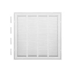
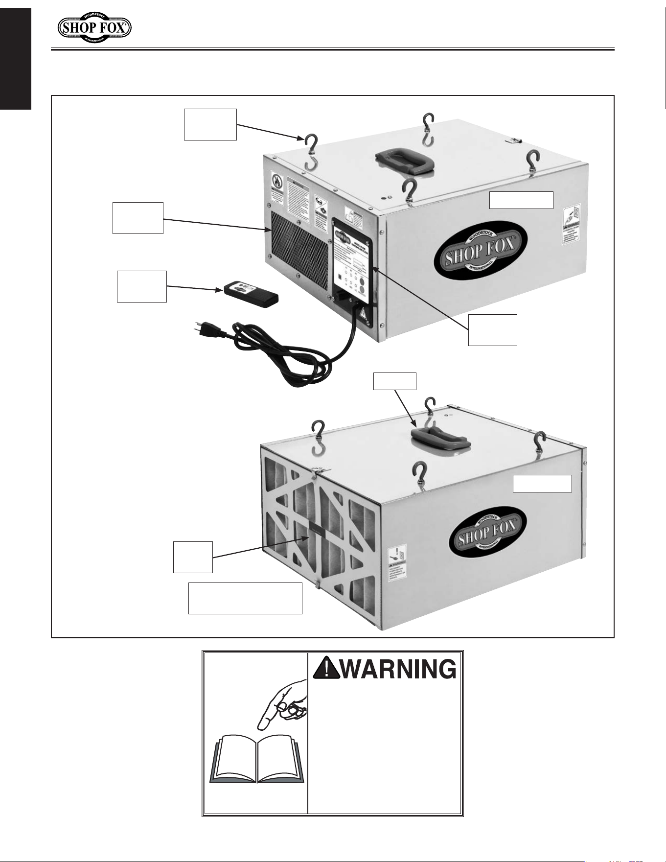
Controls.and.Features
READ.and.understand.this.
entire.manual.before.using.
this.machine..Serious.per-
sonal. injury. may. occur.
if. safety. and. operational.
information. is. not. under-
stood. and. followed.. DO.
NOT. risk. your. safety. by.
not.reading!
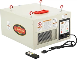
Remote
Control
Machine
Hook
Front View
Control
Panel
Handle
Outer
Filter
Inner Filter
(Behind Outer Filter
Rear View
Exhaust
Port

-5-
Model W1830 (For Machines Mfd. Since 4/15)
SAFETY
SAFETY
READ MANUAL BEFORE OPERATING MACHINE.
FAILURE TO FOLLOW INSTRUCTIONS BELOW WILL
RESULT IN PERSONAL INJURY.
Standard Safety Instructions
1. READ THROUGH THE ENTIRE MANUAL BEFORE STARTING MACHINERY. Machinery presents serious
injury hazards to untrained users.
2. ALWAYS USE ANSI APPROVED SAFETY GLASSES WHEN OPERATING MACHINERY. Everyday eye-
glasses only have impact resistant lenses—they are NOT safety glasses.
3. ALWAYS WEAR A NIOSH APPROVED RESPIRATOR WHEN OPERATING MACHINERY THAT PRODUCES
DUST. Wood dust is a carcinogen and can cause cancer and severe respiratory illnesses.
4. ALWAYS USE HEARING PROTECTION WHEN OPERATING MACHINERY. Machinery noise can cause
permanent hearing damage.
5. WEAR PROPER APPAREL. DO NOT wear loose clothing, gloves, neckties, rings, or jewelry which may
get caught in moving parts. Wear protective hair covering to contain long hair and wear non-slip
footwear.
6. NEVER OPERATE MACHINERY WHEN TIRED, OR UNDER THE INFLUENCE OF DRUGS OR ALCOHOL.
Be mentally alert at all times when running machinery.
7. ONLY ALLOW TRAINED AND PROPERLY SUPERVISED PERSONNEL TO OPERATE MACHINERY. Make
sure operation instructions are safe and clearly understood.
8. KEEP CHILDREN AND VISITORS AWAY. Keep all children and visitors a safe distance from the work
area.
9. MAKE WORKSHOP CHILD PROOF. Use padlocks, master switches, and remove start switch keys.
Indicates an imminently hazardous situation which, if not avoided, WILL
result in death or serious injury.
Indicates a potentially hazardous situation which, if not avoided, COULD
result in death or serious injury.
Indicates a potentially hazardous situation which, if not avoided, MAY
result in minor or moderate injury.
This symbol is used to alert the user to useful information about proper
operation of the equipment, and/or a situation that may cause damage
to the machinery.
NOTICE

-6-
Model W1830 (For Machines Mfd. Since 4/15)
SAFETY
APPROVED OPERATION. Untrained operators
can be seriously hurt by machinery. Only
allow trained or properly supervised people
to use machine. When machine is not being
used, disconnect power, remove switch keys,
or lock-out machine to prevent unauthorized
use—especially around children. Make
workshop kid proof!
ONLY USE AS INTENDED
. Only use machine for
its intended purpose. Never modify or alter
machine for a purpose not intended by the
manufacturer or serious injury may result!
USE RECOMMENDED ACCESSORIES
. Consult
this owner’s manual or the manufacturer for
recommended accessories. Using improper
accessories will increase the risk of serious
injury.
CHILDREN & BYSTANDERS.
Keep children and
bystanders a safe distance away from work
area. Stop using machine if children or
bystanders become a distraction.
REMOV
E ADJUSTING TOOLS. Never leave
adjustment tools, chuck keys, wrenches, etc.
in or on machine—especially near moving
parts. Verify removal before starting!
SECURING WORKPIECE.
When required, use
clamps or vises to secure workpiece. A secured
workpiece protects hands and frees both of
them to operate the machine.
FEED DIRECTION.
Unless otherwise noted, feed
work against the rotation of blades or cutters.
Feeding in the same direction of rotation may
pull your hand into the cut.
GUARDS & COVERS.
Guards and covers can
protect you from accidental contact with
moving parts or flying debris. Make sure
they are properly installed, undamaged, and
working correctly before using machine.
NEVER STAND ON MACHINE.
Serious injury or
accidental contact with cutting tool may
occur if machine is tipped. Machine may be
damaged.
STABLE MACHINE. Unexpected movement during
operations greatly increases the risk of injury
and loss of control. Verify machines are
stable/secure and mobile bases (if used) are
locked before starting.
FORCING MACHINERY. Do not force machine. It
will do the job safer and better at the rate for
which it was designed.
AWKWARD POSITIONS. Keep proper footing and
balance at all times when operating machine.
Do not overreach! Avoid awkward hand
positions that make workpiece control difficult
or increase the risk of accidental injury.
UNATTENDED OPERATION. Never leave machine
running while unattended. Turn machine off
and ensure all moving parts completely stop
before walking away.
MAINTAIN WITH CARE. Follow all maintenance
instructions and lubrication schedules to
keep machine in good working condition. An
improperly maintained machine may increase
the risk of serious injury.
CHECK DAMAGED PARTS. Regularly inspect
machine for damaged parts, loose bolts,
mis-adjusted or mis-aligned parts, binding,
or any other conditions that may affect safe
operation. Always repair or replace damaged
parts, wires, cords, or plugs before operating
machine.
MAINTAIN POWER CORDS. When disconnecting
cord-connected machines from power, grab
and pull the plug—NOT the cord. Pulling the
cord may damage the wires inside. Do not
handle the cord/plug with wet hands. Avoid
cord damage by keeping it away from heated
surfaces, high traffic areas, harsh chemicals,
and wet or damp locations.
EXPERIENCING DIFFICULTIES. If at any time you
are experiencing difficulties performing the
intended operation, stop using the machine!
Contact our Technical Support for help at
(360) 734-3482.
-7-
Model W1830 (For Machines Mfd. Since 4/15)
SAFETY
Additional.Safety.for.Air.Filters
INTENDED.USE. This air filter is designed
to capture dust from ambient air in a
woodworking shop for a short time after
cutting or sanding operations. DO NOT use
this air filter to collect particles of silica,
metal, lead paint, asbestos, or hazardous
bacterium. DO NOT allow this filter to collect
liquids, combustible fumes, burning or
smoking material, or toxic fumes.
HAZARDOUS.DUST. Dust exposure may cause
cancer, birth defects, or long-term respiratory
damage. Be aware of the dust hazards
associated with each workpiece material, and
always wear a NIOSH-approved respirator to
reduce your risk.
LEAD.PAINT.DUST.AND.ASBESTOS.FIBERS. DO
NOT try to collect lead paint or asbestos
fibers with this machine. Due to the high
hazard to human health, these materials must
be collected with special equipment.
DUST.ALLERGIES. Dust from certain woods
may cause an allergic reaction in people and
animals. Make sure you know what type of
wood dust you will be exposed to in case
there is a possibility of an allergic reaction.
WEAR.RESPIRATOR. Fine dust that is too small
to be caught in the filter will be blown into
the ambient air during operation. Wearing a
NIOSH approved respirator during this time
will reduce your risk of permanent respiratory
damage.
EMPTYING.DUST. When removing dust from the
filters, turn OFF the switch, disconnect power,
and wear a respirator and safety glasses.
Empty dust away from ignition sources and
into an approved container.
DISCONNECTING.POWER.SUPPLY. Turn the
switch OFF, disconnect the air filter from the
power supply, and allow the impeller to come
to a complete stop before leaving the machine
unattended or doing any service, cleaning,
maintenance, or adjustments.
REGULAR.CLEANING. For best performance,
regularly check/clean the filters to avoid the
buildup of fine dust. Make sure to regularly
clean the surrounding area where the machine
is operated—excessive dust buildup on
overhead lights, heaters, electrical panels,
or other heat sources will increase the risk of
fire.
SUSPENDED.DUST.PARTICLES.AND.IGNITION.
SOURCES. DO NOT operate the air filter in
areas where explosion risks are high. Areas
of high risk include, but are not limited to,
areas near pilot lights, open flames, or other
ignition sources.
FIRE.SUPPRESSION. Only operate the air filter
in locations that contain a fire suppression
system or have a fire extinguisher nearby.
IMPELLER.HAZARDS. DO NOT place your hands
or tools inside the air filter housing during
operation for any reason. The powerful
suction could easily cause accidental contact
with the impeller which could cause serious
personal injury or damage to the machine.
OPERATING.LOCATION. DO NOT operate the air
filter in rainy or wet locations—exposure to
water may create a shock hazard or decrease
the life of the machine.
USE.this.and.other.machinery.with.caution.and.respect..Always.consider.safety.first,.as.it.applies.
to.your.individual.working.conditions.. No. list. of. safety. guidelines.can.be.complete—every.shop.
environment.is.different..Failure.to.follow.guidelines.could.result.in.serious.personal.injury,.dam-
age.to.equipment.or.poor.work.results.
-8-
Model W1830 (For Machines Mfd. Since 4/15)
ELECTRICAL
ELECTRICAL
Circuit.Requirements
This machine must be connected to the correct size and
type of power supply circuit, or fire or electrical damage
may occur. Read through this section to determine if an
adequate power supply circuit is available. If a correct
circuit is not available, a qualified electrician MUST install
one before you can connect the machine to power.
A power supply circuit includes all electrical equipment
between the breaker box or fuse panel in the building
and the machine. The power supply circuit used for
this machine must be sized to safely handle the full-
load current drawn from the machine for an extended
period of time. (If this machine is connected to a circuit
protected by fuses, use a time delay fuse marked D.)
Circuit.Requirements.for.120V
Circuit.Type....................... 120V,.60.Hz,.Single-Phase
Circuit.Size.............................................. 15.Amps
Plug/Receptacle..................................... NEMA.5-15
Full-Load.Current.Rating
The full-load current rating is the amperage a machine
draws at 100% of the rated output power. On machines
with multiple motors, this is the amperage drawn by the
largest motor or sum of all motors and electrical devices
that might operate at one time during normal operations.
Full-Load.Current.Rating.at.120V......................1.Amp
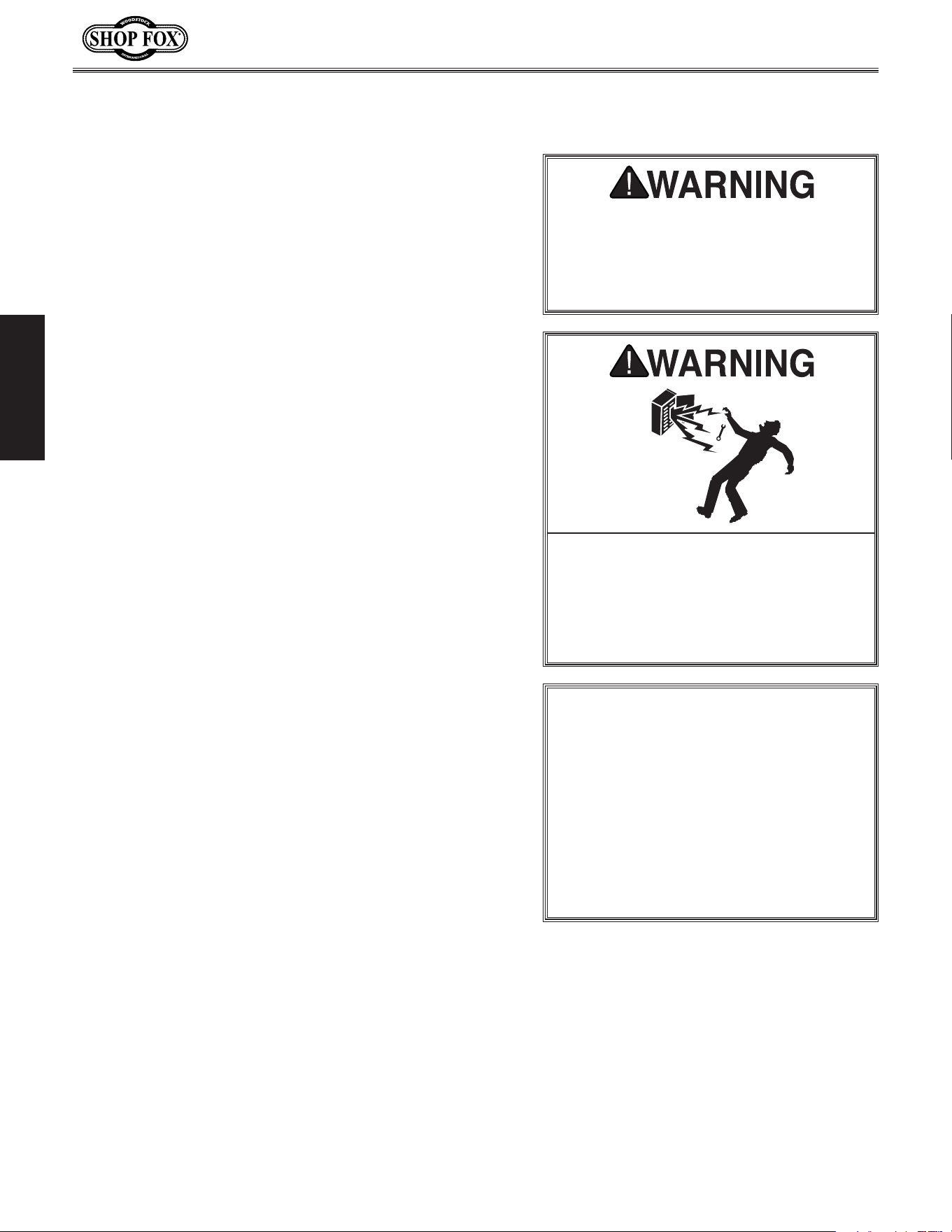
The machine must be properly set up
before it is safe to operate. DO NOT
connect this machine to the power
source until instructed to do later in
this manual.
Incorrectly wiring or grounding this
machine can cause electrocution, fire,
or machine damage. To reduce this risk,
only an electrician or qualified service
personnel should do any required
electrical work on this machine.
NOTICE
The circuit requirements listed in this
manual apply to a dedicated circuit—
where only one machine will be running
at a time. If this machine will be
connected to a shared circuit where
multiple machines will be running at
the same time, consult a qualified
electrician to ensure that the circuit is
properly sized for safe operation.
This machine is prewired to operate on a 120V power
supply circuit that has a verified ground and meets the
following requirements:
-9-
Model W1830 (For Machines Mfd. Since 4/15)
ELECTRICAL
Grounding.Requirements
This machine MUST be grounded. In the event of certain
types of
malfunctions or breakdowns, grounding provides
a path of least resistance for electric current
to travel—in
order
to reduce the risk of electric shock.
Improper connection of the equipment-grounding
wire
will
increase
the risk of electric shock. The wire with green
insulation
(with/without yellow stripes) is the equipment-
grounding
wire. If repair or replacement of the power
cord or plug is necessary, do not connect the equipment-
grounding
wire to a live (current carrying) terminal.
Check with a qualified electrician or service personnel
if
you do not understand these grounding requirements,
or if
you are in doubt about whether the tool is
properly grounded.
If you ever notice that a cord or
plug is damaged or worn, disconnect it from power, and
immediately replace it with a new one.
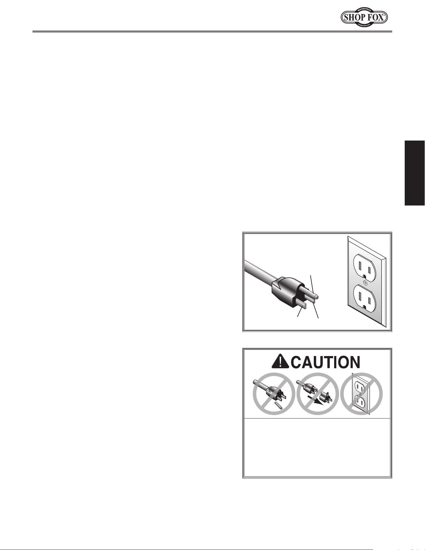
Grounding Prong
Neutral Hot
5-15 PLUG
GROUNDED
5-15 RECEPTACLE
120V
Figure 1. NEMA 5-15 plug & receptacle.
DO NOT modify the provided plug or
use an adapter if the plug will not
fit the receptacle. Instead, have an
electrician install the proper receptacle
on a power supply circuit that meets
the requirements for this machine.
Extension.Cords
We do not recommend using an extension cord with
this machine. Extension cords cause voltage drop, which
may damage electrical components and shorten motor
life. Voltage drop increases with longer extension cords
and smaller gauge sizes (higher gauge numbers indicate
smaller sizes).
Any extension cord used with this machine must contain a
ground wire
, match the required
plug and receptacle, and
meet the following requirements:
Minimum.Gauge.Size.at.120V....................... 14.AWG
Maximum.Length.(Shorter.is.Better).................50.ft.
For.120V.Connection.
This machine is equipped with a power cord that has an
equipment-grounding
wire and NE M A 5-15 grounding plug.
The plug
must only be inserted into a matching
receptacle
(
see Figure) that is properly installed and grounded in
accordance with local codes and ordinances.
-10-
Model W1830 (For Machines Mfd. Since 4/15)
SETUP
Keep. machine. disconnected. from.
power.until.instructed.otherwise.
This machine has been carefully packaged for safe
transportation. If you notice the machine has been
damaged during shipping, please contact your authorized
Shop Fox dealer immediately.
Unpacking
SET UP
The following is a description of the main components
shipped with the Model W1830. Lay the components out
to inventory them.
Note: If you can't find an item on this list, check the
mounting location on the machine or examine the
packaging materials carefully. Occasionally we pre-install
certain components for safer shipping.
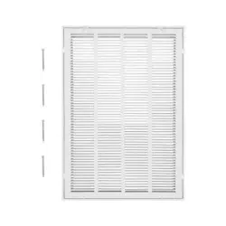
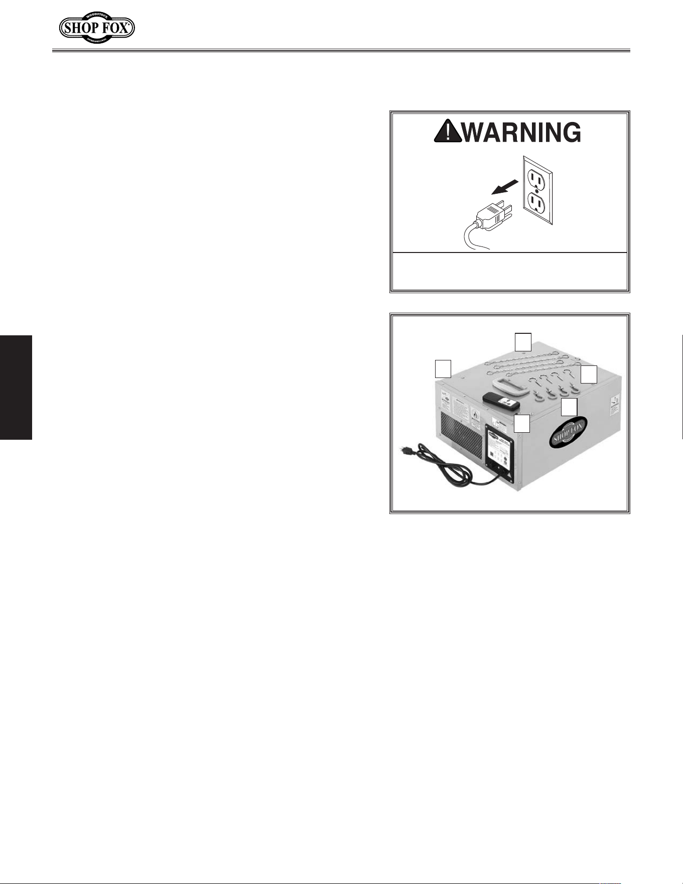
Shipping.Inventory:..(Figure.2). Qty
A. Air Filter Unit ..............................................1
B. Hanging Chains .............................................4
C. Ceiling Hooks ...............................................4
D. Machine Hooks .............................................4
E. Remote Control w/Batteries .............................1
Installed.&.Not.Shown. Qty
• Outer Filter .................................................1
• Inner Filter .................................................1
Inventory
Figure.2. Shipping inventory.
A
C
D
E
B
-11-
Model W1830 (For Machines Mfd. Since 4/15)
SETUP
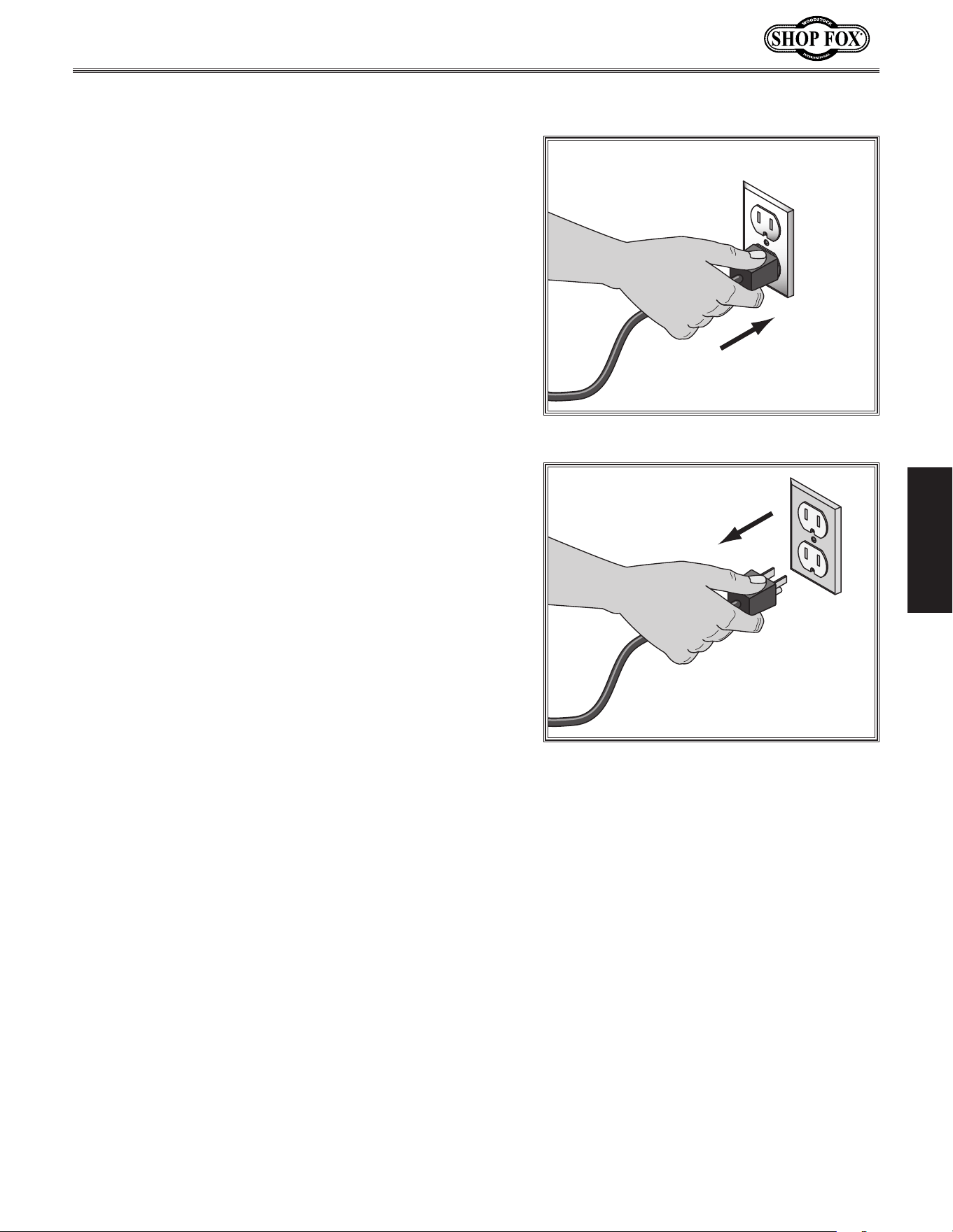
To avoid unexpected startups or property damage, use
the following steps whenever connecting or disconnecting
the machine.
Connecting.Power
Insert the power cord plug into a matching power supply
receptacle. The machine is now connected to the power
source.
Disconnecting.Power
Grasp the molded plug and pull it completely out of the
receptacle. Do not pull by the cord as this may damage
the wires inside.
Power.Connection
Figure.3. Connecting power.
Figure.4. Disconnecting power.
-12-
Model W1830 (For Machines Mfd. Since 4/15)
SETUP
Test. Run
Once you have unpacked the machine, perform a test
run before mounting to the ceiling to make sure it runs
properly.
If, during the test run, you cannot easily locate the source
of an unusual noise or vibration, stop using the machine
immediately, then review the Troubleshooting on Page.
20.
If you still cannot remedy a problem, contact our Tech
Support at (360) 734-3482 for assistance.
To.test.run.the.machine,.do.these.steps:
1. Make sure you have read the safety instructions at
the beginning of the manual.
2. Place the air filter on a workbench or similar stable
surface that can support the load.
3. Connect the air filter to power.
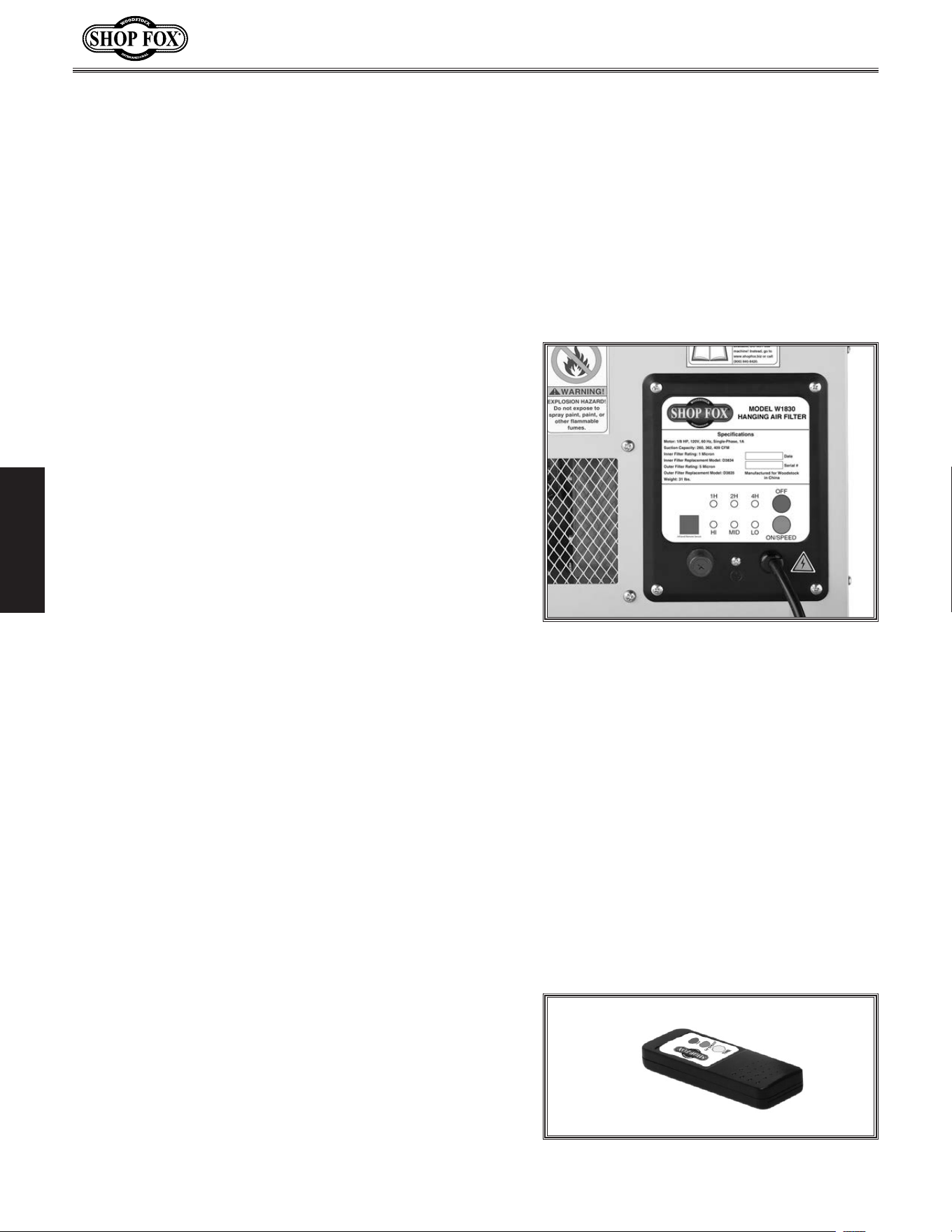
4. Press the ON SPEED button on the control panel of
the air filter (see Figure.5) to turn the unit ON. The
machine should begin to operate.
— Strange or unusual noises should be investigated
and corrected before operating the machine
further. Always disconnect the machine from
power when investigating or correcting potential
problems.
Note: Do not be alarmed if you notice a small
amount of vibration during the Test Run. It is
normal for all air filters to produce a small
amount of vibration during operation. This
vibration is much more noticeable when operating
on a hard surface, such as a workbench, compared
to when operating in a suspended position, as
designed.
5. Push the ON SPEED button repeatedly to cycle
through the three air flow speed options. The lights
on the control panel should display the selected
speed.
6. Press the OFF button to turn the machine OFF.
7. Point the remote control directly at the control
panel, and press the remote control ON SPEED
button to turn the machine ON.
Figure.5. Air filter control panel.
8. Push the remote control ON SPEED
button (see Figure.6) repeatedly to
cycle through the air flow options.
The lights on the control panel should
display the selected speed.
9. Push the remote control TIME button
repeatedly to cycle through the three
time options. The lights on the control
panel should display the amount of
time the air filter will run before
automatically turning OFF.
10. Press the remote control OFF button
to turn the air filter OFF.
Figure.6. Remote control.
-13-
Model W1830 (For Machines Mfd. Since 4/15)
SETUP
Site.Planning
Site planning is an important step to maximize the
effectiveness of the hanging air filter. Air circulation
must be thought out and all obstructions to the air path
considered.
Think of air circulation in terms of the circular motion of
the air before and after the air filter. The air exiting the
filter is exhausted at a higher velocity than that entering
it. Consequently, exhaust being vented inside a building
can have an effect on the pattern of air circulation.
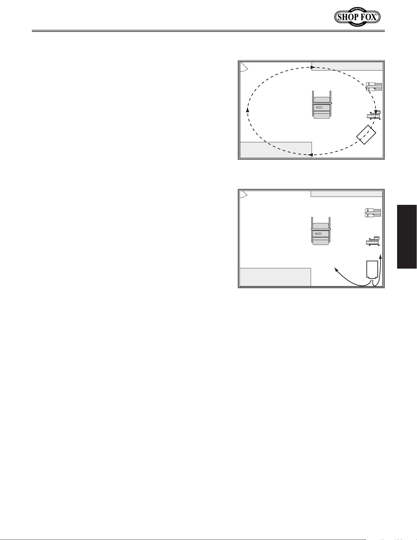
Air circulation patterns will vary depending upon which
air flow speed is used and according to your specific shop
setup. Figure.7 shows an example of good air circulation.
Figure.8 shows an example of poor air circulation, where
the air filter is placed too close to obstructions. In this
situation, the velocity of the air is lost and circulation is
diminished.
Below.is.a.list.of.things.to.keep.in.mind.when.selecting.
a.spot.for.the.air.filter:
• Study your shop layout and try to determine the best
location for the hanging air filter. Air flow that is
obstructed will cause a short cycle effect, producing
unsatisfactory results. There must be a clearance of
at least 3 ft. from any obstructions in front and back
of the unit.
• Try to place the air filter in front of high dust
producers like sanders or near areas where sanding
will take place.
• Do not place the hanging air filter where garage
doors may pass closely or where it may impede
transport or movement of any other object.
• Try to place the unit where it is easy to access for
turning it on, cleaning and maintenance.
It.is.very.impor tant.that.the.hanging.air. filter.be.
supported.properly..Please.follow.these.guidelines.
when.planning.where.to.mount.the.unit:
• Where the mounting brackets attach is the top of
the unit. The hanging air filter can only be secured
by the machine hooks on its top.
Air
Filter
Figure 7. The air filter placement
promotes GOOD circular air motion.
Air
Filter
Figure 8. The air filter placement is too
close to the walls and leaves much of the
room unfiltered.
• Make sure that an electrical outlet
with a properly grounded receptacle is
available at the location you choose.
• The hanging air filter must be
supported by wood joists that are
capable of supporting at least 100 lbs
each. DO NOT attach the hanging air
filter to only sheet rock, press board
or paneling. These materials cannot
support the filter, and it may fall.
• Avoid hitting your head on the hanging
air filter. Make sure there is enough
clearance between the unit and the
ground, especially important in a
basement. If possible, position the air
filter in an area that has little foot
traffic but still offers easy access to
the switch and filters.
-14-
Model W1830 (For Machines Mfd. Since 4/15)
SETUP
The Model W1830 performs best when hung from the
ceiling.
The advantage of having the air filter mounted to the
ceiling is that the air circulation pattern is not blocked by
equipment and obstacles closer to the floor.
When choosing a location to mount the air filter to the
ceiling, keep in mind the clearance necessary underneath
the machine for foot traffic or other operations. The
mounting chains can be used at full length, which will
bring the bottom of the air filter to approximately 25
1
⁄2"
from the ceiling, or the chains can be doubled-up, which
will bring the unit approximately 19
1
⁄2" below the ceiling.
Important: The ceiling hooks must only be screwed into
solid wood. Otherwise, they may pull out under load and
cause the air filter to fall.
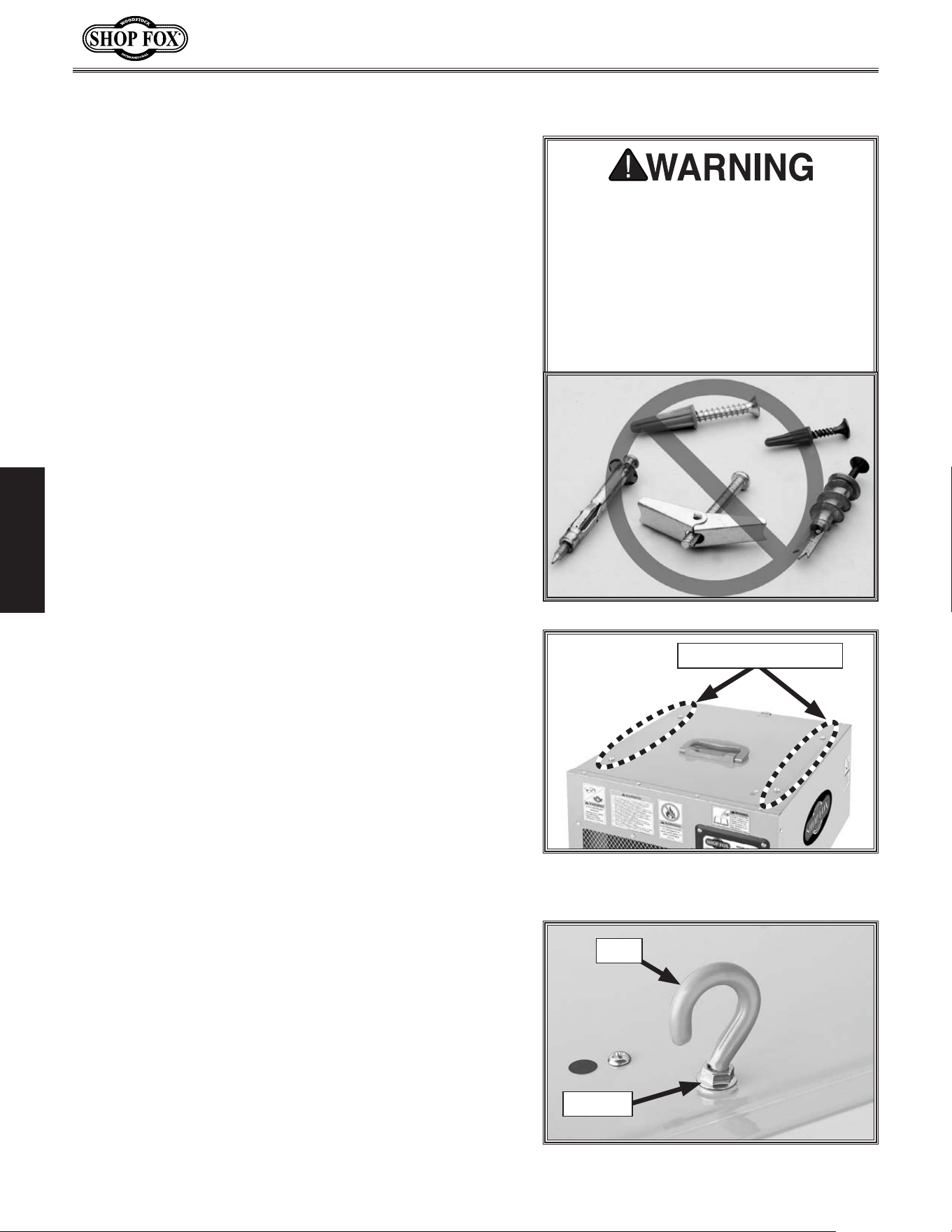
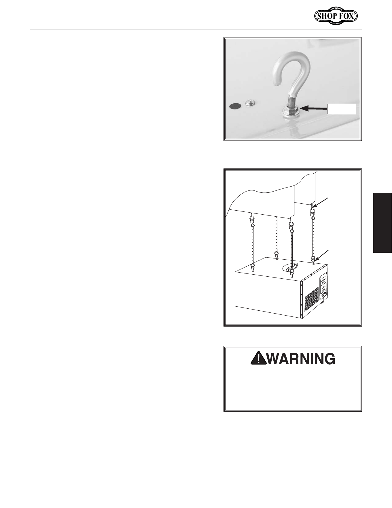
To.mount.the.air.filter.to.the.ceiling,.do.these.steps:
1. Replace the four Phillips head screws shown in
Figure.9 with the four provided machine hooks (see
Figure.10).
2. Tighten each hex nut on the hooks against the air
filter body to secure them in place.
Mounting.to.Ceiling
ONLY.mount.the.air.filter. unit.to.joists.
or. table. that. can. hold. at. least. 100.
lbs.. DO. NOT. mount. the. unit. only. to.
sheet. rock,. pressboard,. paneling,. or.
honeycomb.wall.panels.with.expansion-
type.fasteners..The.fasteners.can.tear.
out.and.the.air.filter.can.fall..Ignoring.
this. caution. can. result. in. injury. or.
property.damage.
Figure 9. Remove these Phillips head
screws.
Phillips Head Screws
Figure 10. Machine hook installed.
Hex Nut
Hook
-15-
Model W1830 (For Machines Mfd. Since 4/15)
SETUP
Note: Some positions for the ceiling hooks may be
slightly uneven from each another. To make up for
this, minor adjustments can be made to the length
of the hanging assembly by adjusting the amount
that the machine hook is threaded into the air filter
housing (see Figure 11). After adjusting the hook
height, tighten the hex nut to secure the hook.
3. Drill a
3
⁄32" pilot hole into the center of the joists at
the mounting locations, then fully thread the ceiling
hooks into the joists (see Figure 12).
Important: If the joists are covered with sheet rock
or paneling, use a stud finder or other device to
locate the center of the joists.
4. Attach the provided chains to the ceiling hooks.
5. With the help of another person to hold the air
filter up, attach the other end of the chains to the
machine hooks.
Figure 11. Machine hook partially
threaded to adjust the hanging length.
Hex Nut
Joist
Ceiling
Hook
Machine
Hook
Figure 12. Air filter mounted to the joists.
THIS AIR FILTER IS TO BE USED FOR
WOOD DUST ONLY..Do.not.use.it.to.
filter.toxic.fumes,.paint.spray,.or.
dissipate.smoke.or.fumes,.which.could.
damage.the.filters.

-16-
Model W1830 (For Machines Mfd. Since 4/15)
OPERATIONS
OPERATIONS
General
Turning.ON.&.OFF
When the air filter is connected to power, press
the ON SPEED button on the air filter control
panel or the remote control to turn the unit ON.
Note: The remote control communicates with
the air filter using infrared (IR) and must be
pointed directly at the air filter control panel to
work properly.
Changing.Air.Flow.Speeds
The air filter can be set to operate in three air
flow speeds—260 (LO), 362 (MED), and 409 CFM
(HI). CFM is the acronym for Cubic Feet per
Minute of air flow that is generated through the
air filter.
To cycle through the available speeds, press the
ON SPEED button on the control panel or remote
control repeatedly. This will illuminate the
corresponding lights on the control panel.
Setting.Timer
The air filter can be set for a timed performance
of 1, 2, or 4 hours. At the end of this time, the
air filter will automatically turn OFF.
To cycle through the available time settings,
press the TIME button on the remote
control repeatedly. This will illuminate the
corresponding lights on the control panel.
Filtering.Performance
When used in conjunction with an efficient
dust collection system, the Model W1830
removes most fine wood particles up to 1
micron from the air. This air filter is capable of
recirculating the air in a room measuring 20'
x 20' x 8' approximately 7.7 times an hour. We
recommend that the volume of air in your room
be recirculated 6–9 times an hour for the best
filtering effect.
Therefore, rooms with a larger volume may
require two or more air filters to achieve proper
filtering.
To.calculate.the.recirculating.rate.for.your.
shop.space,.do.these.steps:
1. Calculate the volume of air in your shop by
multiplying the length x width x height of
the room (see the example below). Then,
divide the volume by the speed (CFM) you
have chosen to operate the air filter. This
will give you how many minutes it takes to
recirculate the air in the room.
Example: The room measures 20' x 20' x 8'
and you are operating the air filter at 409
CFM (HI).
20' x 20' x 8'
= =
3200 ft
3
409 CFM 409 CFM
7.8 Minutes
=
60 Min.
7.8 Min.
7.7 Times per Hour
20' x 20' x 8'
= =
3200 ft
3
409 CFM 409 CFM
7.8 Minutes
=
60 Min.
7.8 Min.
7.7 Times per Hour
2. Calculate how many times per hour the
room volume is recirculated through the
air filter by dividing 60 minutes by the
circulating time from Step.1. This will give
you how many times an hour the air in the
room is recirculated through the air filter.
Ma chine.Storage
When the air filter is not in use, unplug the
power cord from the power source. Secure the
power cord away from potential hazards, such as
high traffic areas, sharp objects, heat sources,
harsh chemicals or fumes, damp areas, etc.
-17-
Model W1830 (For Machines Mfd. Since 4/15)
OPERATIONS
ACCESSORIES
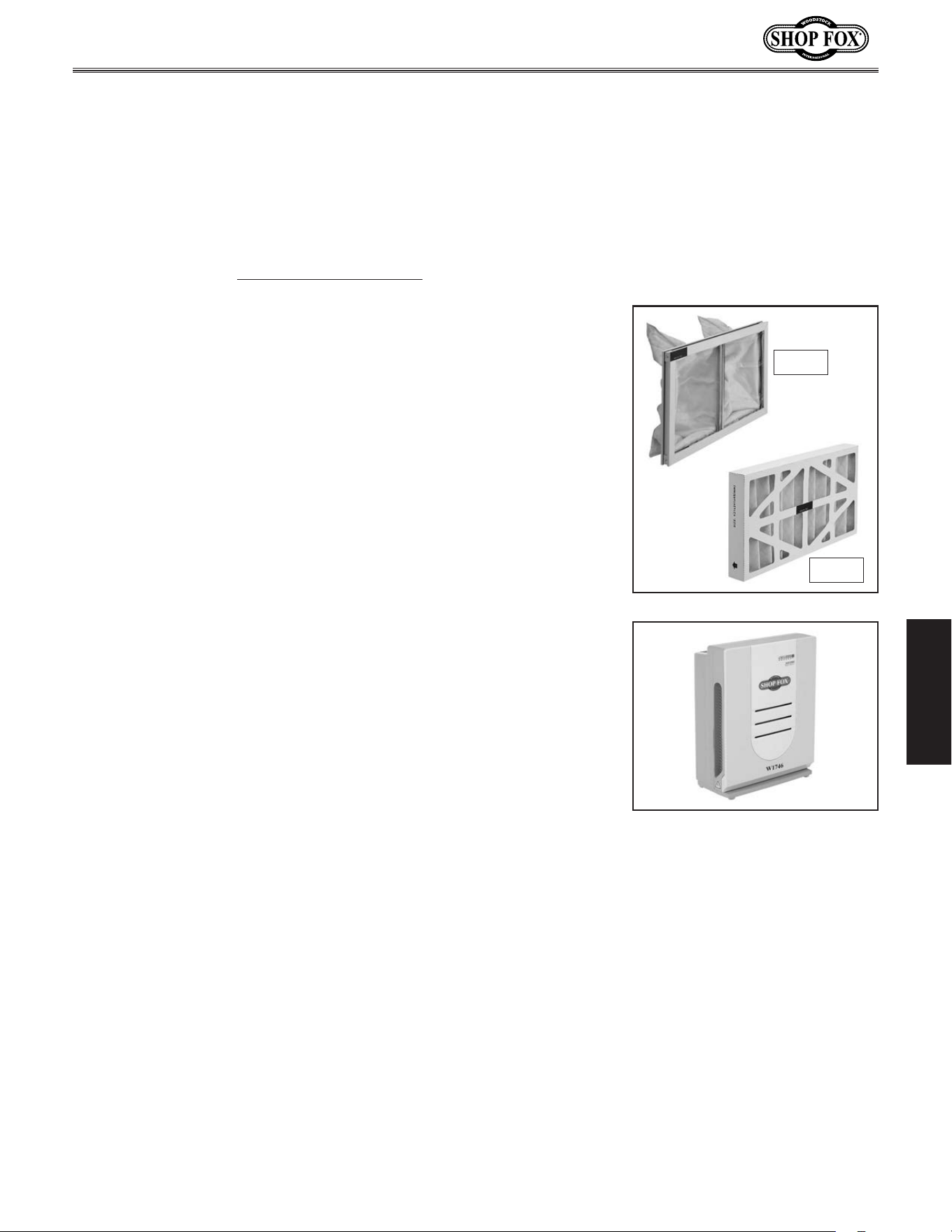
Air.Filter.Accessories
The following Air Filter accessories may be available through your local Woodstock International Inc.
Dealer. If you do not have a dealer in your area, these products are also available through online dealers.
Please call or e-mail Woodstock International Inc. Customer Service to get a current listing of dealers at:
1-800-840-8420 or at sales@woodstockint.com.
D3834—Inner.Filter.for.Model.W1830
D3835—Outer.Filter.for.Model.W1830
We recommend that you keep a set of filters on hand to ensure
uninterrupted service of your air filter.
The Shop.Fox.Model.W1746 is one machine that will sit in the shop
and gather dust—fine dust that is! With its three speed fan, automatic
shut-off and 0.3 micron filter, this fine dust air filter circulates shop
air and captures the fine dust that otherwise stays suspended. Even
with an efficient dust collector, if other machines are making dust, you
need this fine air filter.
D3835
D3834
-18-
Model W1830 (For Machines Mfd. Since 4/15)
MAINTENANCE
MAINTENANCE
The amount of air filter operation has a direct bearing on
when you must clean or replace the filters.
To maintain efficient operation, check the filters
approximately every 40 hours of use in light or moderately
dusty environments. In very dusty environments, check
the filters every eight hours of use. Always wear a
respirator when checking the filters.
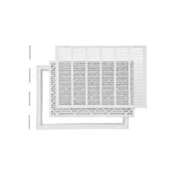
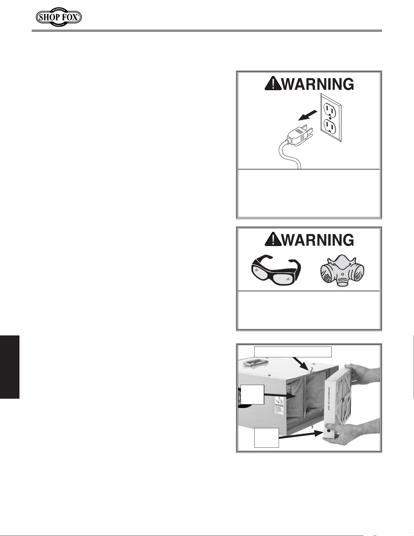
To.change.and.service.the.filters,.do.these.steps:
1. DISCONNECT MACHINE FROM POWER!
2. Un-latch the filter retaining clips from the top and
bottom of the unit, as shown in Figure.13, and
remove the outer filter. Place the filter in a trash
bag and shake it gently to remove the bulk of the
dust.
If you choose to use compressed air to further clean
the filter, do so outdoors and in an appropriate
environment where people are not in the immediate
vicinity.
3. Remove the inner filter, place it inside a trash bag
and gently shake the dust from the inside of the
filter.
Optional: Wash the inner filter with water to remove
the remaining dust, then let it air dry completely.
4. Re-install the inner filter, then re-install the outer
filter with the wire mesh facing to the inside.
5. Re-latch the retaining clips to secure the filters.
Note: During regular use the filters can be cleaned
several times before replacement becomes necessary. To
determine whether the filters need to be replaced, hold
them up to the sunlight and visually inspect them. If you
cannot see through the filters due to caked dust and
grim, replace them before putting air filter back into
operation.
Cleani ng.Filters
Keep.the.air.filter.unit..unplugged.
during.all.maintenance.procedures..
Ignoring.this.warnin g.may.result.in.
laceration.or.amputation.injuries.from.
accidental.startup!
Always.wear.a.respirator.and.safety.
glasses.when.cleaning.the.f ilters..
Sawdust.may.cause.allergic.reactions.
or.respiratory.problems.
Figure.13. Filters exposed for cleaning.
Retaining Clip (1 of 2)
Inner
Filter
Outer
Filter
-19-
Model W1830 (For Machines Mfd. Since 4/15)
SERVICE
SERVICE
This section covers the most common service adjustments
or procedures that may need to be made during the life
of your machine.
If you require additional machine service not included
in this section, please contact Woodstock International
Technical Support at (360) 734-3482 or send e-mail to:
tech-support@shopfox.biz.
General
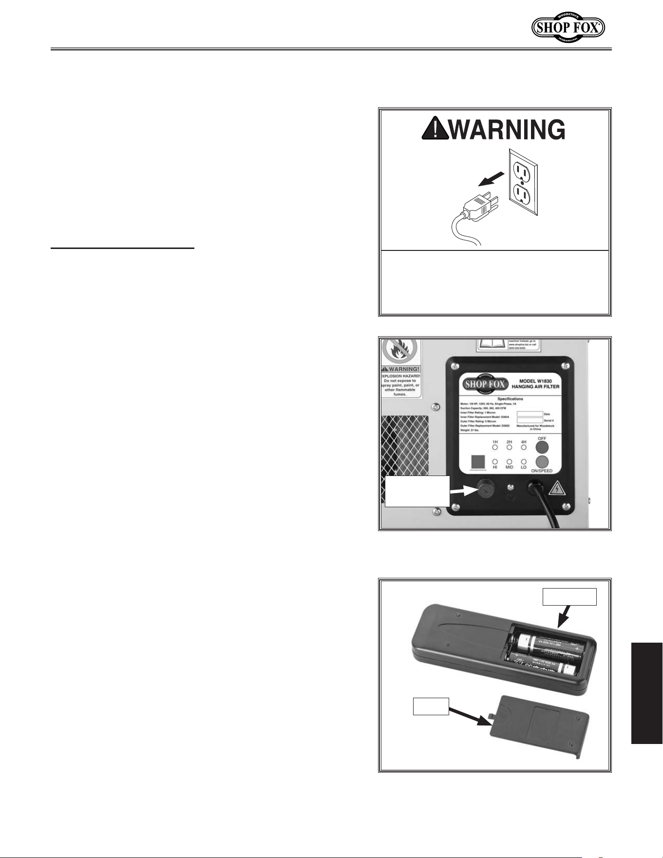
Replacing.Fuse
MAKE. SURE. that. your. machine. is.
unplugged. during. all. service. proce-
dures!. If. this. warning. is. ignored,. seri-
ous.personal.injury.may.occur.
The fuse on the control panel will blow in the case of a
thermal overload.
Replace the fuse only with a fast-acting, 2 amp, 250V fuse
(Part Number X1830055).
Tool.Needed. Qty
Phillips Screwdriver #2 .........................................1
To.replace.the.machine.fuse,.do.these.steps:
1. DISCONNECT MACHINE FROM POWER!
2. Unthread the fuse holder cap from the control panel
(see Figure.14) and remove it. The fuse will come
out with it.
3. Replace the fuse and fully thread the cap in to
secure it.
Remote.Control.Battery.
Replace ment
The remote control uses two AA batteries. To replace
them, slide the battery compartment cover down and off
the remote (see Figure.15). Insert the batteries in the
proper direction and replace the cover.
Figure 15. Remote control battery
compartment cover removed.
Batteries
Cover
Figure 14. Fuse holder cap on the control
panel.
Fuse
Holder Cap
-20-
Model W1830 (For Machines Mfd. Since 4/15)
SERVICE
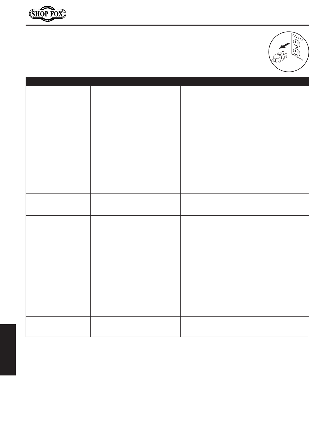
Troubleshooting
This section covers the most common problems and corrections with this type of
machine. WARNING!.DO.NOT.make.any.adjustments.until.power.is.disconnected.and.
moving.parts.have.come.to.a.complete.stop!
PROBLEM POSSIBLE.CAUSE CORRECTIVE.ACTION
Machine does not start or a
breaker trips.
1. Power supply switched OFF or is at
fault.
2. Remote control not working or bat-
teries are dead.
3. Infrared transmission is blocked or
remote too far away.
4. Wall circuit breaker tripped.
5. Control panel fuse blown.
6. Wiring is open/has high resistance.
7. Infrared receiver at fault.
8. Control panel ON SPEED button at
fault.
9. Motor at fault.
1. Ensure power supply is ON/has correct voltage.
2. Replace batteries; point remote control directly at
control panel.
3. Make sure the infrared receiver on the control panel
is not blocked; try using the remote closer to the
filter.
4. Ensure circuit size is correct/replace weak breaker.
5. Check filters/resolve reason for blown fuse; replace
fuse (see Page 19).
6. Check/fix broken, disconnected, or corroded wires.
7. Inspect/replace if faulty.
8. Replace faulty ON SPEED button.
9. Test/repair/replace.
Machine stalls or is under-
powered.
1. Motor overheated.
2. Run capacitor at fault.
3. Motor at fault.
1. Clean filters to reduce load on motor.
2. Test/repair/replace.
3. Test/repair/replace.
Machine has vibration or
noisy operation.
1. Motor or component loose.
2. Motor fan rubbing on fan cover.
3. Motor bearings at fault.
1. Inspect/replace damaged bolts/nuts, and re-tighten
with thread locking fluid.
2. Fix/replace fan cover; replace loose/damaged fan.
3. Test by rotating shaft; rotational grinding/loose
shaft requires bearing replacement.
Loud, repetitious noise, or
excessive vibration coming
from air filter.
1. Air filter is not mounted properly
and wobbles.
2. Impeller fan is damaged, loose, or
severely unbalanced.
3. The motor mounting is loose.
4. Motor fan housing is dented, caus-
ing the motor fan blade to hit the
housing while spinning.
1. Stabilize the air filter.
2. Unplug air filter, and inspect the impeller for dents,
bends, loose fins. Replace impeller if any damage is
found.
3. Make sure all fasteners on the air filter are tight.
4. Replace motor fan housing.
Air filter does not ade-
quately collect dust; poor
performance.
1. The filters are dirty. 1. Clean the filters.
-21-
Model W1830 (For Machines Mfd. Since 4/15)
SERVICE
These pages are current at the time of printing. However, in the spirit of improvement, we may
make changes to the electrical systems of future machines. Study this diagram carefully. If you notice
differences between your machine and these wiring diagrams, call Woodstock International Technical
Support at (360) 734-3482.
SHOCK HAZARD.
Working on wiring that is
connected to a power source is extremely
dangerous. Touching electrified parts will
result in personal injury including but not
limited to severe burns, electrocution,
or death. Disconnect the power from
the machine before servicing electrical
components!
QUALIFIED ELECTRICIAN
. Due to the inherent
hazards of electricity, only a qualified
electrician should perform wiring tasks on this
machine. If you are not a qualified electrician,
get help from one before attempting any kind
of wiring job.
WIRE CONNECTIONS.
All connections must be
tight to prevent wires from loosening during
machine operation. Double-check all wires
disconnected or connected during any wiring
task to ensure tight connections.
WIRE/COMPONENT DAMAGE
. Damaged wires
or components increase the risk of serious
personal injury, fire, or machine damage.
If you notice that any wires or components
are damaged while performing a wiring task,
replace those wires or components before
completing the task.
MOTOR WIRING
. The motor wiring shown in these
diagrams is current at the time of printing,
but it may not match your machine. Always
use the wiring diagram inside the motor
junction box.
MODIFICATIONS. Using aftermarket parts or
modifying the wiring beyond what is shown
in the diagram may lead to unpredictable
results, including serious injury or fire.
CAPACITORS/INVERTERS. Some capacitors and
power inverters store an electrical charge for
up to five minutes after being disconnected
from the power source. To avoid being
shocked, wait at least this long before working
on these components.
ELECTRICAL REQUIREMENTS. You MUST follow
the electrical requirements at the beginning
of this manual when connecting your machine
to a power source.
EXPERIENCING DIFFICULTIES. If you are
experiencing difficulties understanding the
information included in this section, contact
our Technical Support at (360) 734-3482.
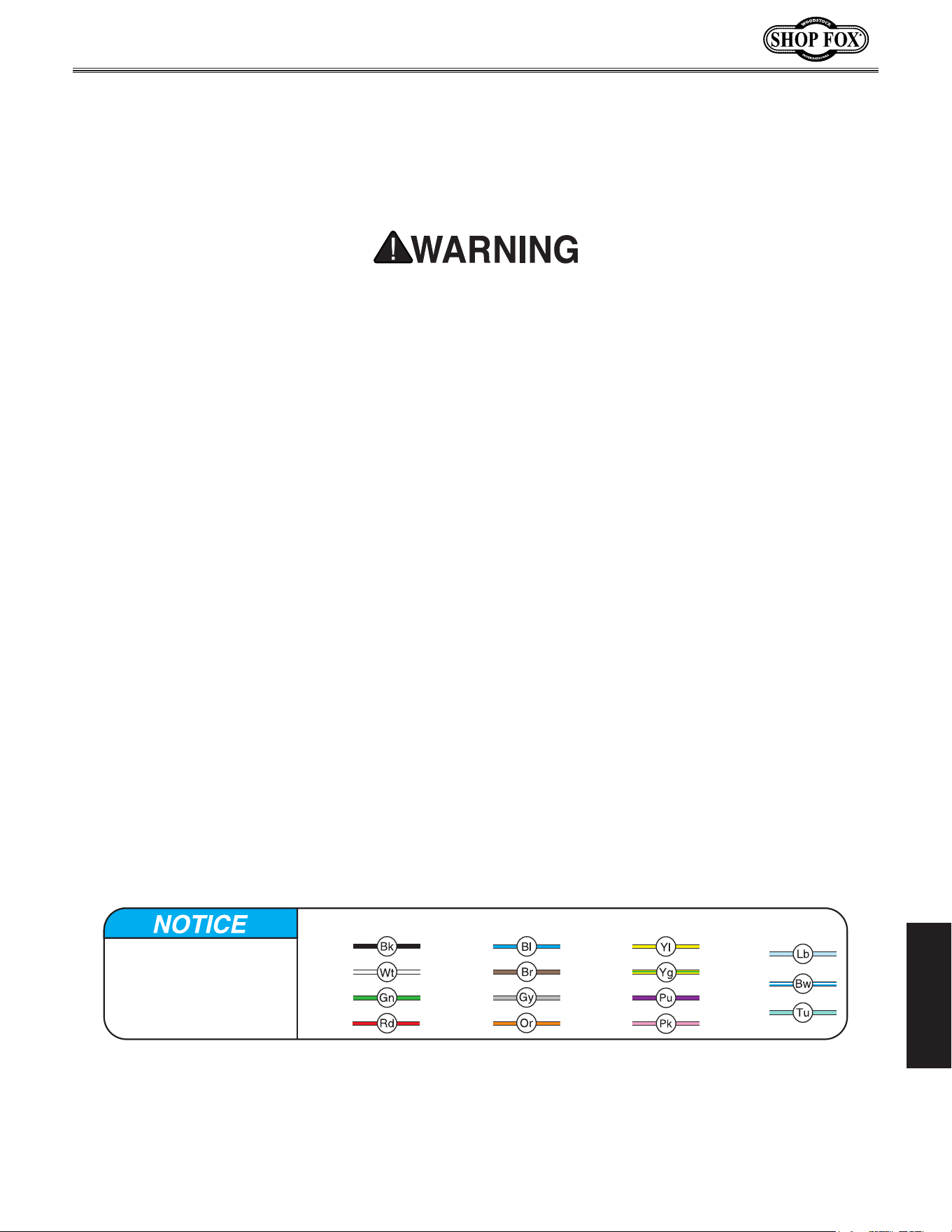
Electrical.Safety.Instructions
The photos and diagrams
included in this section are
best viewed in color. You
can view these pages in
color at www.shopfox.biz.
BLACK
WHITE
GREEN
RED
BLUE
BROWN
GRAY
ORANGE
YELLOW
YELLOW
GREEN
PURPLE
PINK
LIGHT
BLUE
BLUE
WHITE
TUR-
QUOISE
WIRING DIAGRAM COLOR KEY
-22-
Model W1830 (For Machines Mfd. Since 4/15)
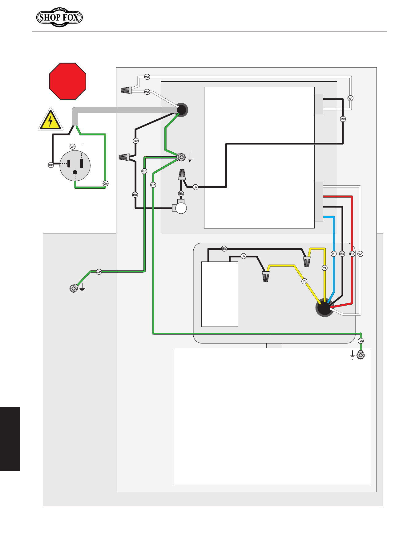
SERVICE
STOP
Read
Page 21
Before
Wiring
Electrical.Wiring.Dia gram
Ground
Neutral
Hot
Ground
Ground
Impeller
Housing
Motor
Cabinet
Power
Cord
Fuse
F2A250V
Control
Panel
110VAC 5-15 Plug
(As Recommended)
Run Capacitor
8MFD 375VAC
Ground
-23-
Model W1830 (For Machines Mfd. Since 4/15)
PARTS
101
101
102
103
104
105
106
107
107
108
108
109
109
110
111
112
113
114
115
116
256
250
251
257
258
259
PARTS
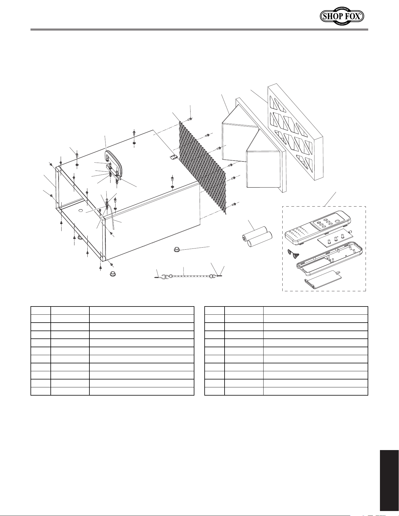
Cabinet.&.Remote.Control
REF PART # DESCRIPTION REF PART # DESCRIPTION
101 XPHTEK15M TAP SCREW M4 X 10 112 X1830112 GROUND WIRE 18AWG 335MM
102 X1830102 CABINET 113 X1830113 WIRE MESH 251 X 528MM
103 XPS14M PHLP HD SCR M6-1 X 12 114 D3834 INNER FILTER 421 X 241 X 160MM
104 X1830104 CABINET HANDLE 115 D3835 OUTER FILTER 421 X 241 X 45MM
105 X1830105 HANDLE BRACKET 116 X1830116 RUBBER FOOT
106 XPS40M PHLP HD SCR M5-.8 X 16 250 X1830250 REMOTE CONTROL UNIT
107 XPW02M FLAT WASHER 5MM 251 XPBATTAA BATTERY AA
108 XPLW01M LOCK WASHER 5MM 256 X1830256 THREADED HOOK M6-1 X 35
109 XPN06M HEX NUT M5-.8 257 X1830257 HANGING CHAIN 11-1/2"
110 XPS08M PHLP HD SCR M5-.8 X 12 258 X1830258 HOOK SCREW M6 X 25
111 XPTLW02M EXT TOOTH WASHER 5MM 259 XPFN02M FLANGE NUT M6-1
-24-
Model W1830 (For Machines Mfd. Since 4/15)
PARTS
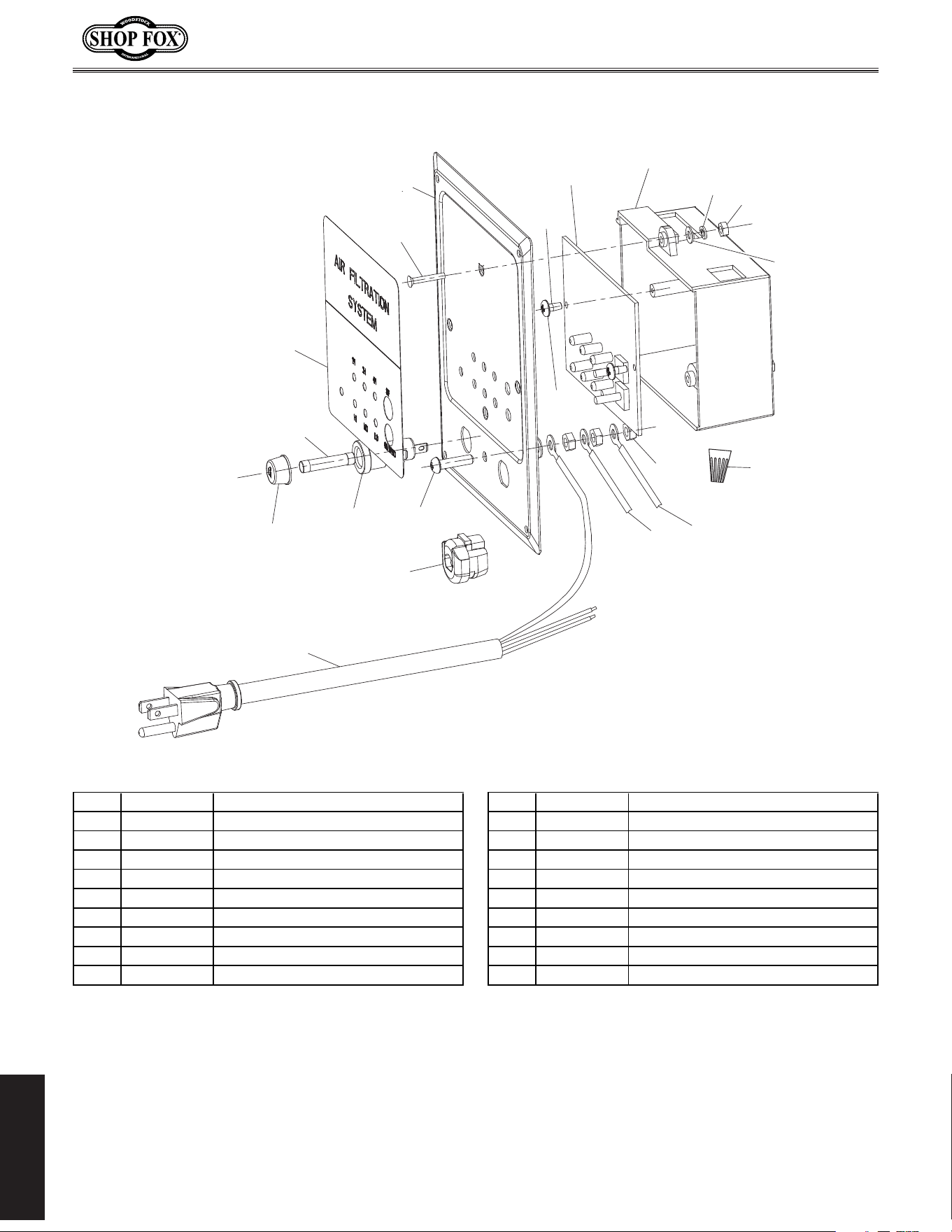
Control.Panel
109
112
150
151
152
153
154
155
156
157
158
159
160
161
162
163
164
165
166
167
REF PART # DESCRIPTION REF PART # DESCRIPTION
109 XPN06M HEX NUT M5-.8 158 X1830158 CONTROL PANEL PLATE
112 X1830112 GROUND WIRE 18AWG 335MM 159 X1830159 INSULATED FLAT WASHER 3MM
150 X1830150 POWER CORD 18G 3W 72" 5-15 160 XPHTEK31M TAP SCREW M4 X 14
151 X1830151 STRAIN RELIEF 6P-4 161 X1830161 PRINTED CIRCUIT BOARD
152 XPS06M PHLP HD SCR M5-.8 X 20 162 X1830162 CONTROL PANEL BOX
153 X1830153 FUSE HOLDER CFH052S CR3-13 163 XPW07M FLAT WASHER 3MM
154 X1830154 FUSE HOLDER CAP 164 XPLW09M LOCK WASHER 3MM
155 X1830155 FUSE F2A250V 165 XPN07M HEX NUT M3-.5
156 X1830156 CONTROL PANEL LABEL 166 X1830166 WIRE NUT 18G
157 XPFH85M FLAT HD SCR M3-.5 X 30 167 X1830167 WIRE 18G 6-3/4"
-25-
Model W1830 (For Machines Mfd. Since 4/15)
PARTS
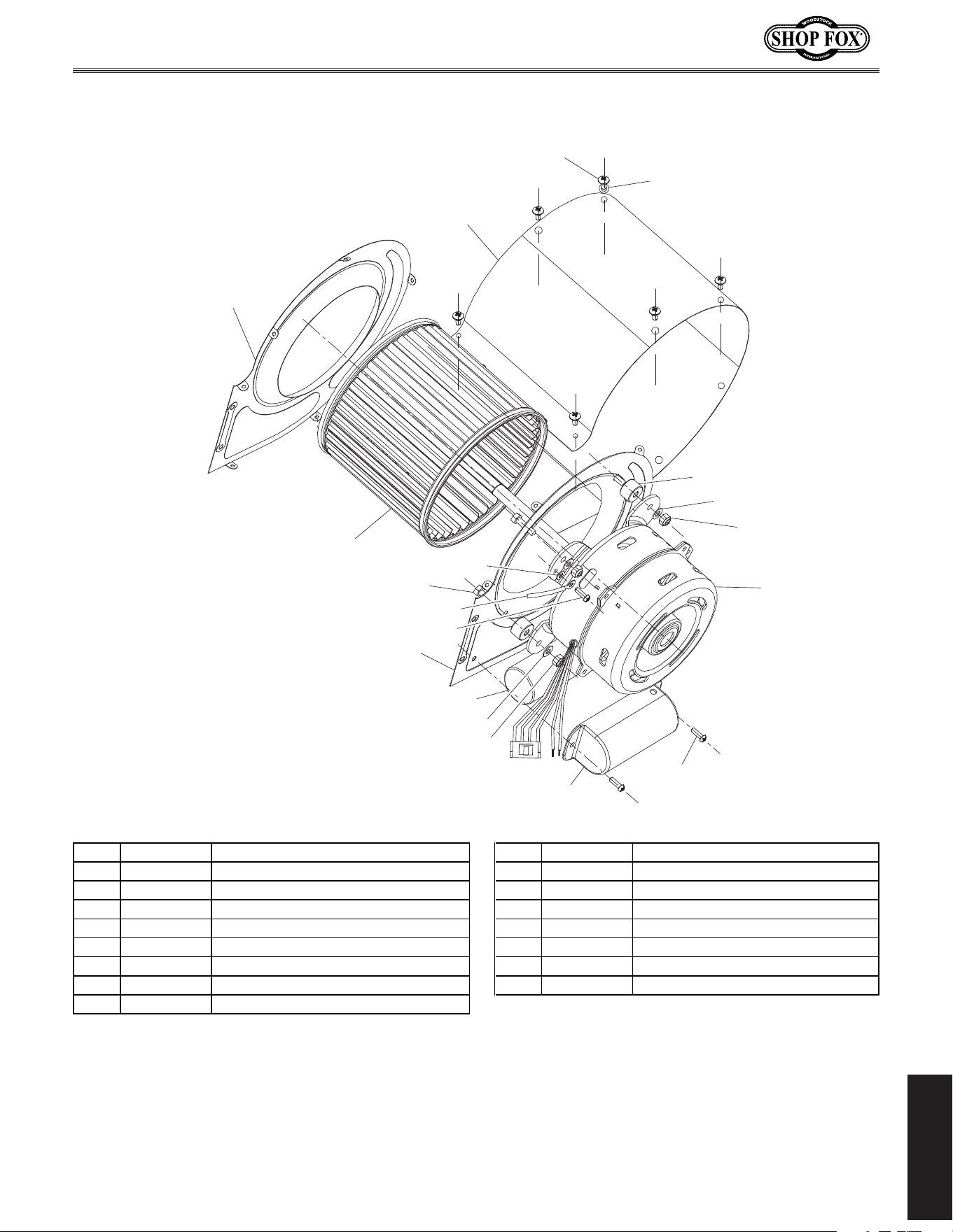
Motor.&.Impeller
101
101
167
200
201
202
202
203
204*
205
206
207*
208*
208A Includes
204, 207, & 208
209
210
211
211
212
213
*
REF PART # DESCRIPTION REF PART # DESCRIPTION
101 XPHTEK15M TAP SCREW M4 X 10 207 X1830207 REAR IMPELLER HOUSING COVER
167 X1830167 WIRE 18G 6-3/4" 208A X1830208A IMPELLER HOUSING ASSEMBLY
200 X1830200 CAPACITOR COVER 208 X1830208 IMPELLER HOUSING
201 XPTLW01M EXT TOOTH WASHER 4MM 209 X1830209 RUBBER SPACER
202 XPW02M FLAT WASHER 5MM 210 XPWF05M FENDER WASHER 5MM
203 X1830203 R CAPACITOR 8M 375V 1-1/4 X 2-1/2 211 XPLN02M LOCK NUT M5-.8
204 X1830204 FRONT IMPELLER HOUSING COVER 212 X1830212 MOTOR 1/8HP 120V 60HZ
205 XPB94M HEX BOLT M5-.8 X 25 213 XPS02M PHLP HD SCR M4-.7 X 12
206 X1830206 SQUIRREL CAGE IMPELLER
-26-
Model W1830 (For Machines Mfd. Since 4/15)
PARTS
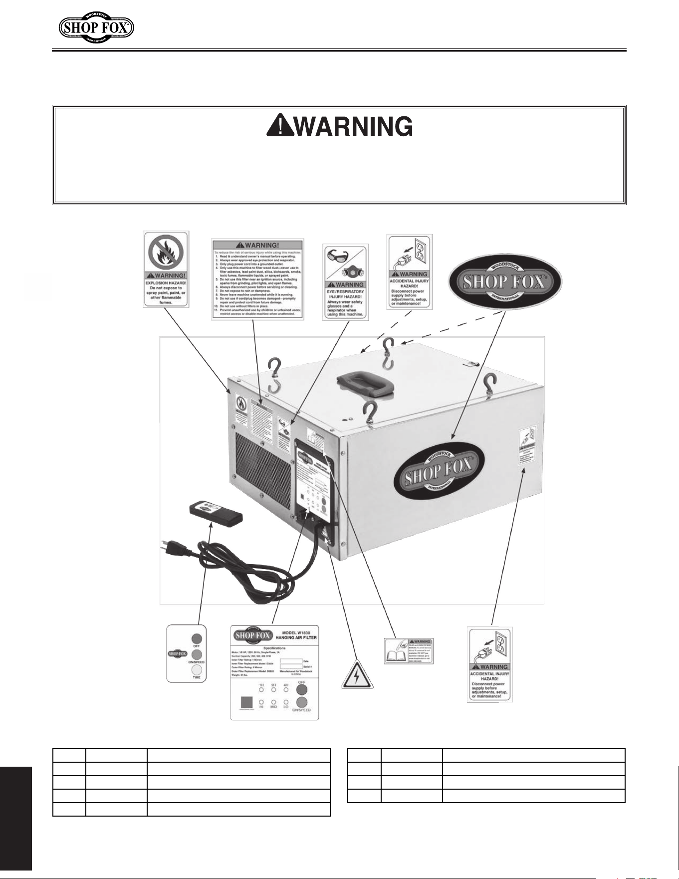
Label.Placement
300
301
302
302
303
304
305
306V2
307
309
REF PART # DESCRIPTION REF PART # DESCRIPTION
300 X1830300 EXPLOSION HAZARD LABEL 305 XLABEL-04 ELECTRICITY LABEL
301 X1830301 GENERAL WARNINGS LABEL 306V2 X1830306V2 CONTROL PANEL LABEL ETL V2.07.14
302 XLABEL-24 DISCONNECT LABEL 307 X1830307 REMOTE CONTROL LABEL
303 XLABEL-06 EYE/LUNG HAZARD LABEL 309 X1830309 SHOP FOX LABEL
304 XLABEL-08A READ MANUAL LABEL
Safety.labels.warn.about.machine.hazards.and.how.to.prevent.serious.personal.injury..The.owner.
of.this.machine.MUST.maintain.the.original.location.and.readability.of.all.labels.on.this.machine..
If.any.label.is.removed.or.becomes.unreadable,.REPLACE.that.label.before.allowing.machine.to.be.
operated.again..Contact.us.at.(360).734-3482.or.www.shopfoxtools.com.to.order.new.labels..
Model W1830 (For Machines Mfg. Since 1/12)

tape along edges--please do not staple
Fold along dotted lIne
Fold along dotted lIne
Woodstock international inc.
p.o. box 2309
bellingham, Wa 98227-2309
place
stamp
Here

WAR RANTY
Woodstock International, Inc. warrants all Shop Fox machinery to be free of defects from workmanship
and materials for a period of two years from the date of original purchase by the original owner.
This warranty does not apply to defects due directly or indirectly to misuse, abuse, negligence or
accidents, lack of maintenance, or reimbursement of third party expenses incurred.
Woodstock International, Inc. will repair, replace, or arrange for a dealer refund at its expense and
at its option, the Shop Fox machine or machine part, which in proper and intended use has proven to
be defective, provided that the original owner returns the product prepaid to an authorized warranty
or repair facility as designated by our Bellingham, Washington office with proof of their purchase of
the product within two years, and provides Woodstock International, Inc. reasonable opportunity to
verify the alleged defect through inspection. If it is determined there is no defect, or that the defect
resulted from causes not within the scope of Woodstock International Inc.'s warranty, then the original
owner must bear the cost of storing and returning the product.
This is Woodstock International, Inc.’s sole written warranty and any and all warranties that may be
implied by law, including any merchantability or fitness, for any particular purpose, are hereby limited
to the duration of this written warranty. We do not warrant that Shop Fox machinery complies with
the provisions of any law, acts or electrical codes. We do not reimburse for third party repairs. In no
event shall Woodstock International, Inc.’s liability under this limited warranty exceed the purchase
price paid for the product, and any legal actions brought against Woodstock International, Inc. shall be
tried in the State of Washington, County of Whatcom. We shall in no event be liable for death, injuries
to persons or property or for incidental, contingent, special or consequential damages arising from the
use of our products.
Every effort has been made to ensure that all Shop Fox machinery meets high quality and durability
standards. We reserve the right to change specifications at any time because of our commitment to
continuously improve the quality of our products.
WARRANTY

High Quality Machines and Tools
Woodstock International, Inc. carries thousands of products designed
to meet the needs of today's woodworkers and metalworkers.
Ask your dealer about these fine products: