INSTRUCTION MANUAL
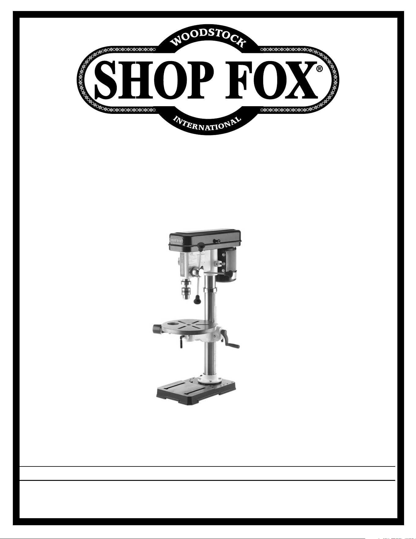
MODEL W1668
13
1
⁄4" Oscillating Drill Press
Phone: 1-800-840-8420 • On-Line Technical Support: [email protected]
COPYRIGHT © 2000 BY WOODSTOCK INTERNATIONAL, INC.
WARNING: NO PORTION OF THIS MANUAL MAY BE REPRODUCED IN ANY SHAPE OR FORM WITHOUT
THE WRITTEN APPROVAL OF WOODSTOCK INTERNATIONAL, INC.
Printed in China

-1-
Table Of Contents
PAGE
1. INTRODUCTION
ABOUT YOUR NEW DRILL PRESS ......................................................2
WOODSTOCK SERVICE AND SUPPORT ................................................2
WARRANTY AND RETURNS..............................................................3
MACHINE SPECIFICATIONS ..............................................................3
2. SAFETY..........................................................................................4
STANDARD SAFETY INSTRUCTIONS ................................................4-5
DRILL PRESS SAFETY ....................................................................5
ELECTRICAL REQUIREMENTS ..........................................................6
AVOIDING POTENTIAL INJURIES ......................................................7
3. ASSEMBLY INSTRUCTIONS ..................................................................8
BOX CONTENTS ..........................................................................8
BASE AND COLUMN ......................................................................9
DUST PORT ................................................................................9
TABLE SUPPORT ....................................................................10-11
MOUNTING TABLE ......................................................................11
HEADSTOCK ..............................................................................12
DRILL CHUCK ............................................................................13
HANDLES..................................................................................13
4. ADJUSTMENTS ..............................................................................14
SPEED CHANGE ......................................................................14-15
SPINDLE ADJUSTMENTS ..............................................................15
OSCILLATING FEATURE ................................................................16
TABLE ADJUSTMENTS ..................................................................17
5. OPERATIONS..................................................................................18
TEST RUN ................................................................................18
DRILL CHANGES ........................................................................19
6. MAINTENANCE................................................................................20
GENERAL..................................................................................20
TABLE AND BASE........................................................................20
LUBRICATION ............................................................................20
7. CLOSURE ......................................................................................21
PARTS BREAKDOWN AND PARTS LISTS ........................................22-23
YOUR NOTES ............................................................................24
ASSEMBLY
OPERATIONS
MAINTENANCE
PARTS
ADJUSTMENTS
SAFETY
INTRODUCTION
USE THE QUICK GUIDE PAGE LABELS TO SEARCH OUT INFORMATION FAST!

-2-
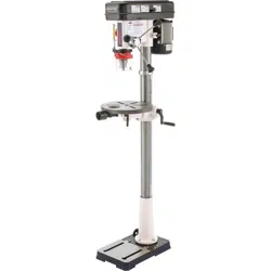
INTRODUCTION
ABOUT YOUR NEW DRILL PRESS
This new Shop Fox
®
Oscillating Drill Press has been specially designed by Woodstock
International, Inc. to provide many years of trouble free service. Close attention to detail,
ruggedly built parts and a rigid quality control program assure safe and reliable operation.
The
Shop Fox
®
Model W1668 is a drill press and oscillating sander in one compact machine. It is
capable of a wide variety of drilling and sanding operations. A sanding spindle is included for
use with drums ranging in size from 1" to 2" diameter and 4
1
⁄4" long. Purchasing drums and
sleeves will allow you to sand small or finely detailed pieces and with the oscillating feature,
your abrasives will last longer and provide a smoother finish. Included are table inserts to give
maximum support for the workpiece and a dust port to connect to your dust collection system.
The W1668 is packaged with a drill chuck, chuck key, motor and paddle switch with removable
safety key.
Woodstock International, Inc. is committed to customer satisfaction in providing this manual. It
is our intent to make sure all the information necessary for safety, ease of assembly, practical
use and durability of this product be included.
If you should have any comments regarding this manual, please feel free to contact us at:
Woodstock International, Inc.
P.O. Box 2309
Bellingham, WA 98227
WOODSTOCK SERVICE AND SUPPORT
We stand behind our machines! In the event that a defect is found, parts are missing or questions arise
about your machine, please contact Woodstock Service and Support at:
1-360-734-3482
or
Our knowledgeable staff will help you troubleshoot problems, send out parts or arrange warranty
returns.
INTRODUCTION

-3-
WARRANTY AND RETURNS
Woodstock International, Inc. warrants all SHOP FOX
®
machinery to be free of defects from workman-
ship and materials for a period of 2 years from the date of original purchase by the original owner. This
warranty does not apply to defects due directly or indirectly to misuse, abuse, negligence or accidents,
lack of maintenance, or to repair or alterations made or specifically authorized by anyone other than
Woodstock International, Inc.
Woodstock International, Inc. will repair or replace, at its expense and at its option, the SHOP FOX
®
machine or machine part which in normal use has proven to be defective, provided that the original
owner returns the product prepaid to the SHOP FOX
®
factory service center or authorized repair facility
designated by our Bellingham, WA office, with proof of their purchase of the product within 2 years, and
provides Woodstock International, Inc. reasonable opportunity to verify the alleged defect through
inspection. If it is determined there is no defect, or that the defect resulted from causes not within the
scope of Woodstock International Inc.'s warranty, then the original owner must bear the cost of storing
and returning the product.
This is Woodstock International, Inc.'s sole written warranty and any and all warranties that may be
implied by law, including any merchantability or fitness, for any particular purpose, are hereby limited
to the duration of this written warranty. We do not warrant that SHOP FOX
®
machinery complies with
the provisions of any law or acts. In no event shall Woodstock International, Inc.'s liability under this war-
ranty exceed the purchase price paid for the product, and any legal actions brought against Woodstock
International, Inc. shall be tried in the State of Washington, County of Whatcom. We shall in no event
be liable for death, injuries to persons or property or for incidental, contingent, special or consequen-
tial damages arising from the use of our products.
Every effort has been made to ensure that all SHOP FOX
®
machinery meets high quality and durability
standards. We reserve the right to change specifications at any time because of our commitment to con-
tinuously improve the quality of our products.
Machine Specifications
Capacities:
Oscillating Stoke Length............................................................................................
3
⁄
4"
Spindle Travel ......................................................................................................3
1
⁄4''
Max. Distance, Spindle to Base ....................................................................................24''
Max. Distance, Spindle to Table................................................................................17
1
⁄
4''
Spindle Taper ......................................................................................................B-16
Swing................................................................................................................13
1
⁄4''
Chuck Size ........................................................................................
5
⁄8'' (13mm), keyed
Speeds..............................................................................................12, Belt Controlled
Range of Speeds ......................
250, 330, 380, 500, 590, 640, 980, 1530, 1600, 1870, 2580, 3050 RPM
Drilling Capacity ..............................................................................
3
⁄4'' Diameter in Steel
Motor:
Type ................................................................................TEFC Capacitor Start Induction
Horsepower........................................................................................................
3
⁄
4 HP
Phase ⁄ Cycle ..................................................................................Single Phase ⁄ 60 Hz
Voltage ..............................................................................................................110V
Amps......................................................................................................................9
RPM ..................................................................................................................1720
Power Transfer .......................................................................................... V-Belt Drive
Bearings ......................................................................Shielded & Lubricated Ball Bearings
Switch ................................................................Toggle ON/OFF Switch, w/ Safety Lock Tab
INTRODUCTION

-4-
READ MANUAL BEFORE OPERATING MACHINE
FAILURE TO FOLLOW INSTRUCTIONS BELOW WILL
RESULT IN PERSONAL INJURY
SAFETY FIRST!
1. Thoroughly read the instruction manual before operating your machine. Learn the applications,
limitations and potential hazards of this machine. Keep manual in a safe, convenient place for future
reference.
2. Keep work area clean and well lighted. Clutter and inadequate lighting invite potential hazards.
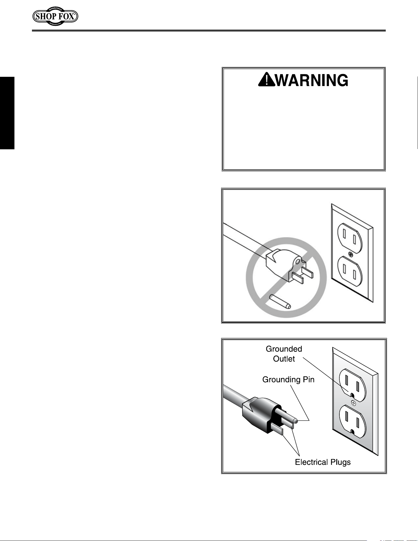
3. Ground all tools. If a machine is equipped with a three-prong plug, it must be plugged into a three-
hole electrical outlet or grounded extension cord. If using an adapter to aid in accommodating a two-
hole receptacle, ground using a screw to a known ground.
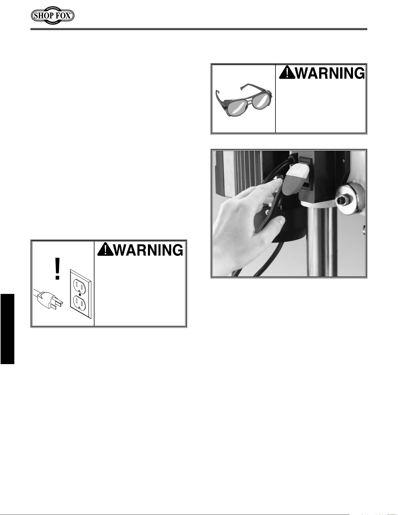
4. Wear eye protection at all times. Use safety glasses with side shields or safety goggles, meeting the
national safety standards, while operating this machine.
5. Avoid dangerous environment. Do not operate this machine in wet or open flame environments.
Airborne dust particles could cause an explosion and severe fire hazard.
6. Ensure all guards are securely in place and in working condition.
7. Make sure switch is in the “OFF” position before connecting power to machine.
8. Keep work area clean; free of clutter, grease, etc.
9. Keep children and visitors away. All visitors should be kept a safe distance away while operating
unit.
10. Childproof workshop with padlocks, master switches or by removing starter keys.
Indicates an imminently hazardous situation which, if not avoided, WILL
result in death or serious injury.
Indicates a potentially hazardous situation which, if not avoided, COULD
result in death or serious injury.
Indicates a potentially hazardous situation which, if not avoided, MAY
result in minor or moderate injury. It may also be used to alert against
unsafe practices.
This symbol is used to alert the user to useful information about proper
operation of the equipment.
NOTICE
SAFETY

1. Always operate your drill press at speeds that are appropriate for the drill bit size and the mate-
rial that you are drilling.
2. Feed the drill bit evenly into the workpiece. Back the bit out of deep holes and clear the chips
with a brush after you have turned the machine off.
3. Make sure the drill bit you are using is tightened properly. Use only round, hex or triangular shank
drill bits.
4. Never do maintenance or change speeds with this machine plugged in.
5. Never use tools that are in poor condition. Cutting tools that are dull or damaged are difficult to
control and may cause serious injury.
6. Never drill sheet metal unless it is clamped securely to the table.
7. Work should be positioned in such a way as to avoid drilling into the table.
8. A face guard used with safety glasses is recommended.
9. Always clamp workpiece securely to table before drilling. Never hold a workpiece by hand while
drilling.
10. Always remove handles before using oscillating feature.
11. Habits – good and bad – are hard to break. Develop good habits in your shop and safety will become
second-nature to you.
Additional Safety Instructions For Drill Presses
11. Disconnect machine when cleaning, adjusting or servicing.
12. Do not force tool. The machine will do a safer and better job at the rate for which it was designed.
13. Use correct tool. Do not force machine or attachment to do a job for which it was not designed.
14. Wear proper apparel. Do not wear loose clothing, neck ties, gloves, jewelry, etc.
15. Remove adjusting keys and wrenches. Before turning the machine on, make it a habit to check that
all adjusting keys and wrenches have been removed.
16. Use proper extension cord. When using an extension cord, make sure it is in good condition. When
extension cord is 100’ and less in length, use those that are rated Hard Service (grade S) or better,
and that have a conductor size of 16 A.W.G. A drop in line voltage, loss of power and overheating
can result when using an undersized cord. The extension cord should have a ground wire and ground
plug pin, as well.
17. Keep proper footing and balance at all times.
18. Do not leave machine unattended. Wait until it comes to a complete stop before leaving the area.
19. Perform machine maintenance and care. Follow lubrication and accessory attachment instructions
in the manual.
20. Keep machine away from open flame. Operating machines near pilot lights and/or open flames cre-
ates a high risk if dust is dispersed in the area. Dust particles and an ignition source may cause an
explosion. Do not operate the machine in high risk areas, including but not limited to, those men-
tioned above.
SAFETY
-5-
-6-
110V Operation
ELECTRICAL REQUIREMENTS
When it is necessary to use an extension cord,
use the following guidelines:
•Use cords rated for Hard Service
•Never exceed a length of 100 feet
•Use cords with 14 ga. wire or bigger
•Insure cord has a ground wire and pin
•Do not use cords in need of repair
Extension Cords
Grounding
This equipment must be grounded. Verify
that any existing electrical outlet and circuit
you intend to plug into is actually grounded.
If it is not, it will be necessary to run a sep-
arate 12 A.W.G. copper grounding wire from
the outlet to a known ground. Under no cir-
cumstances should the grounding pin from
any three-pronged plug be removed. Serious
injury may occur.
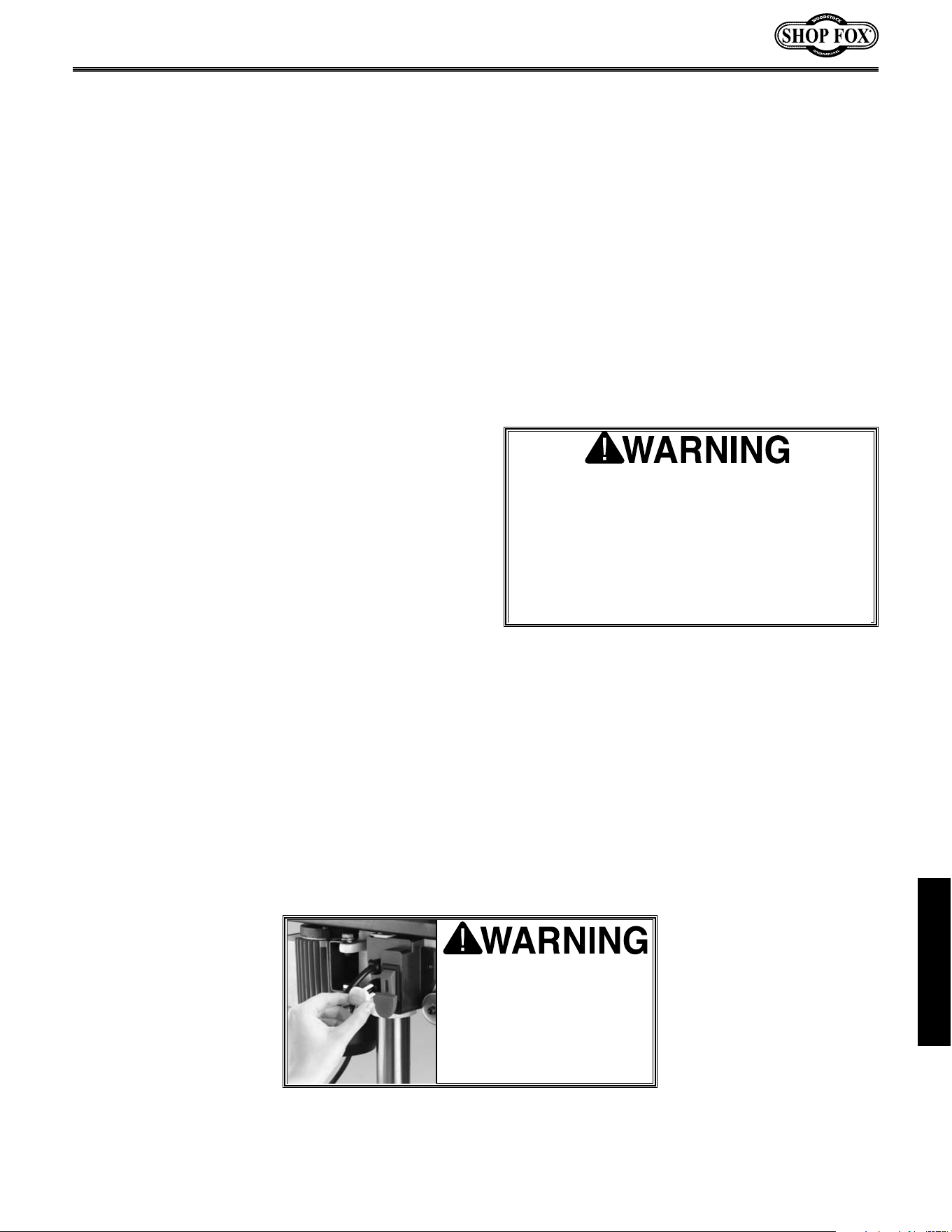
This machine must be grounded! See Figure 1.
The electrical cord supplied with the Shop Fox
®
W1668 comes with a grounding pin. Do not
remove it. If your outlet does not accommodate
a ground pin, have it replaced by a qualified
electrician or have an appropriate adapter
installed with a proven ground source. An
adapter does not ensure a grounded system if
the adapter is not grounded.
The Shop Fox
®
W1668 13
1
⁄4" Oscillating Drill
Press can only be operated at 110 volts. The
motor supplied with your new drill press is rated
at
3
⁄4 horse power and will draw approximately
9 amps. When choosing an outlet for this
machine, consider using one with a 15 amp cir-
cuit breaker or fuse. Keep in mind that a circuit
being used by other machines or tools at the
same time will add to the electrical load being
applied by the drill press. Add up the load rat-
ings of all machines on the circuit. If this num-
ber exceeds the rating of the circuit breaker or
fuse, use a different outlet.
Figure 1. Typical 110V 3-prong plug and outlet.
SAFETY
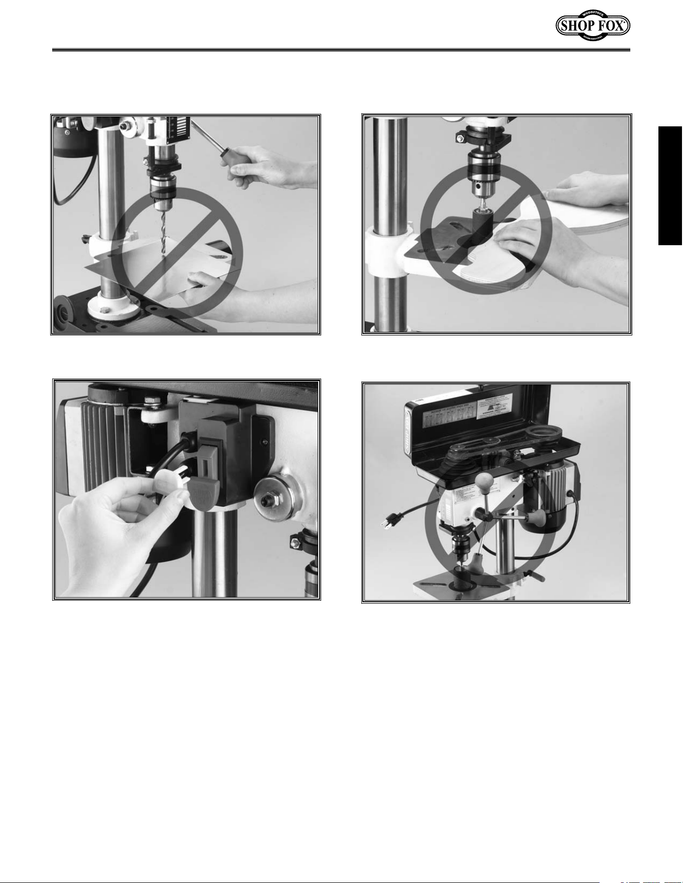
AVOIDING POTENTIAL INJURIES
-7-
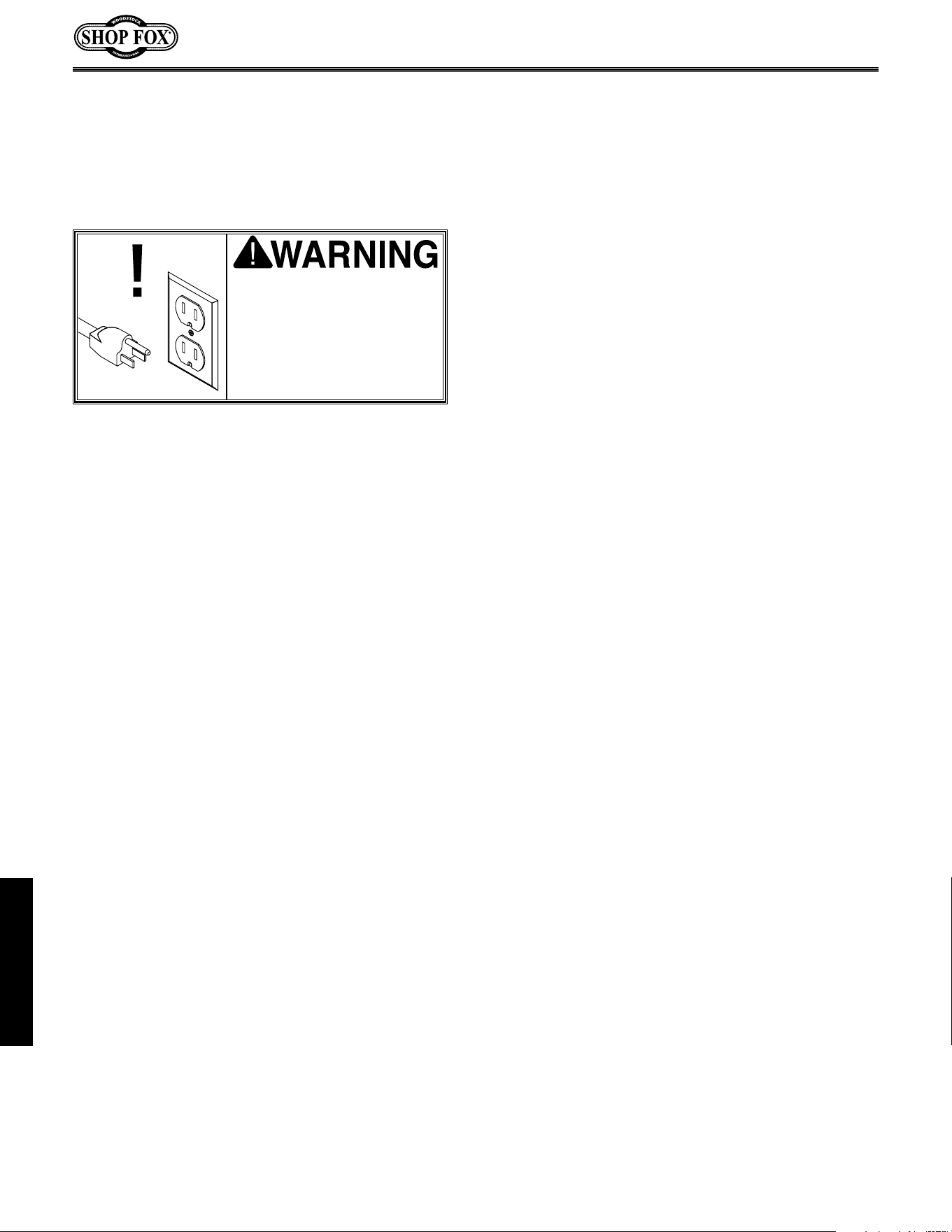
Figure 2. Never drill, holding workpiece by hand.
Figure 3. Keep fingers away from spinning tool.
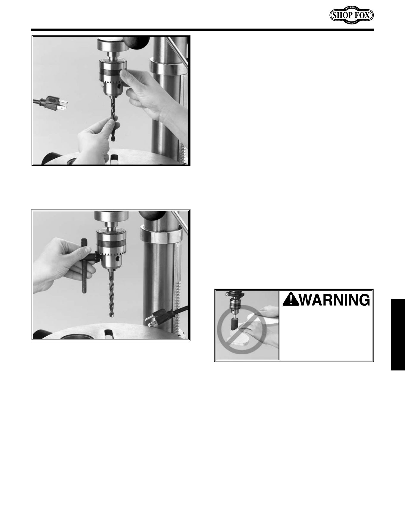
Fig. 4. Remove Switch Safety Key when not in use.
Figure 5. Remove handles when using oscillating
mode.
SAFETY
-8-
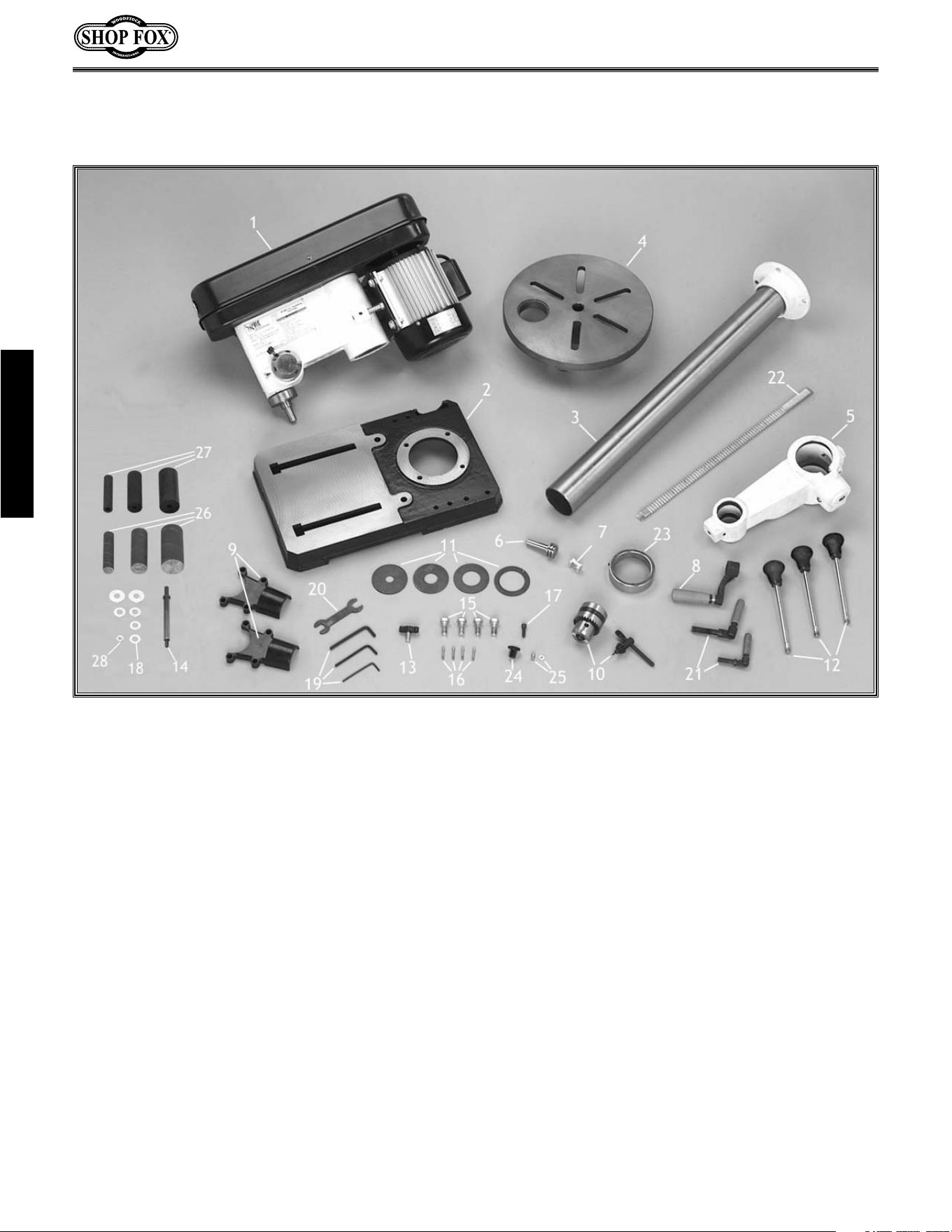
Figure 6. Components laid out for identification.
The following is a description of the components shipped with the Shop Fox
®
W1668 Oscillating Drill
Press. It is recommended that the components be laid out in a similar fashion to those in Figure 6. This
will help in identification before beginning assembly. Should any part be missing, examine the packag-
ing carefully and check under the belt guard. If any key parts are missing call Woodstock International
at 360-734-3482 or at [email protected].
1. Headstock Assembly
2. Base
3. Column
4. Table
5. Table Bracket
6. Pinion Gear
7. Clamp Shoe
8. Hand Crank
9. Dust Port
10. Drill Chuck and Key
11. Table Inserts (4)
12. Spindle Handles (3)
13. Belt Tension Lock Knob
14. Sanding Mandrel
15. Hex Head Bolts (4)
16. Phillips
®
Head Screws (4)
17. Cap Screw
18. Mandrel Washers (4)
19. Allen
®
Wrenches (3)
20. Open End Wrench
21. Lock Handles (2)
22. Rack
23. Rack Ring
24. Belt Cover Knob
25. Machine Screw w/ Washer
26. Sanding Sleeves
27. Sanding Drums
28. Mandrel Nut
ASSEMBLY INSTRUCTIONS
ASSEMBLY
-9-
ASSEMBLY
While the main components of the Shop Fox
®
W1668 Oscillating Drill Press are assembled at the factory,
some assembly is required. The following is the recommended sequence best suited for final assembly.
TOOLS REQUIRED: You will need a 10mm, 12mm and 14mm open end wrench, a flat tipped screwdriv-
er, a Phillips
®
screwdriver (not supplied) and a 3mm, 4mm and 5mm Allen
®
wrench (supplied).
Base/Column
1. Ensure machine is unplugged before begin-
ning assembly!
2. Place base on a stable work bench. Make
sure the work bench will handle the weight
of the drill press and workpiece.
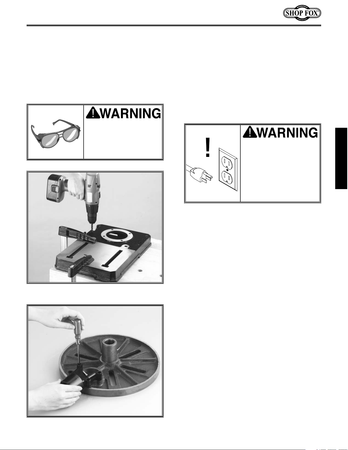
3. It is recommended that the base be secured
to the bench. Otherwise a tipping hazard
will exist.
4. Clamp the base to the table once a suitable
location is found. Use
5
⁄16" lag bolts or
through bolts with washers, lock washers
and nuts. Use the mounting holes in the
base as a drill guide. Figure 7.
5. Place the column on the base and line up
the 4 mounting holes. Secure tightly with
the M10-1.5 x 25mm hex head bolts using
open end wrench provided.
Figure 7.
Using holes in base as drill guide.
Do not connect the
machine to power at this
time. The drill press must
remain unplugged through-
out the entire assembly
process. Failure to do this
may result in serious per-
sonal injury.
Dust Port
The two-piece dust port is assembled to the bot-
tom of the table using the four M4- 0.7 x 22mm
Phillip
®
head screws.
Figure 8.
Figure 8.
Installing the dust port.
Wear safety glasses dur-
ing the entire assembly
process. Failure to com-
ply may result in serious
personal injury.
ASSEMBLY
-10-
Figure 11.
Lock shoe Inserted into table bracket.
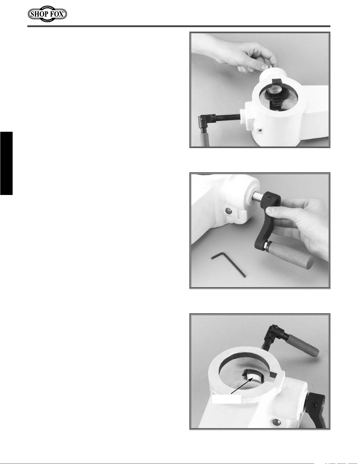
Figure 9.
Insert the pinion gear from the inside.
Figure 10.
Align setscrew with flat on pinion.
Table Support
1. Thread the 12mm table lock handle 3 turns
into the table support bracket.
2. Insert the pinion into the hole on the side of
the table support bracket from the inside,
starting with the pinion shaft.
Figure 9.
Align setscrew in crank handle with flat,
Figure 10,
on pinion shaft and secure using
the 3mm Allen
®
wrench provided.
3. Insert the lock shoe into the table support
bracket and secure with setscrews on either
side. Figure 11.
Lock shoe
ASSEMBLY
-11-
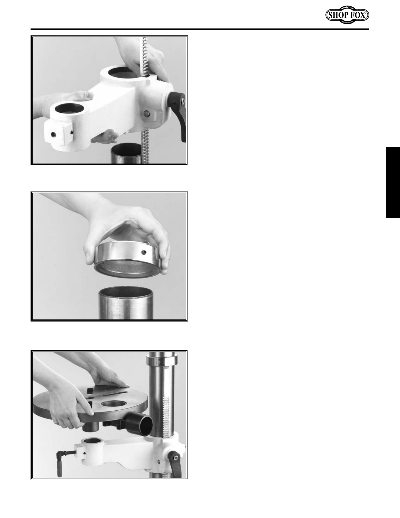
Figure 12.
Hold rack in position while installing.
Figure 13.
Inside bevel in the correct position.
Figure 14.
Lock shoe in place and secured.
Table Support, Cont.
4. Examine the rack and note that the gear
teeth extend further on one end than the
other. Insert the rack into the table support
bracket and align with pocket. The end of
the rack where the gear teeth are closest to
the end should be positioned down when
the support bracket is oriented as in
Figure
12.
The gear teeth on the rack must also
face out.
5. Slide the table support bracket onto the
column while holding the rack in place.
Allow the bracket to go down until the bot-
tom of the rack contacts the shoulder on the
column support. Secure the table with the
lock handle.
6. Slide the column ring onto the column with the
inside bevel in the down position. Figure 13.
Adjust the ring until the tip of the rack fits
inside the bevel. Tighten the setscrew on the
ring. Do not over tighten.
Use caution when tightening set screw. Over tight-
ening will split column ring.
Mounting Table
1. Thread the 10mm lock handle into the table
bracket.
2. Insert the lock shoe into the table support
bracket and secure with setscrews on either
side. Refer to step 3 under heading Table
Support if needed.
3. Align the shaft under the table with the hole
on the end of the table support bracket.
Figure 14.
ASSEMBLY
-12-
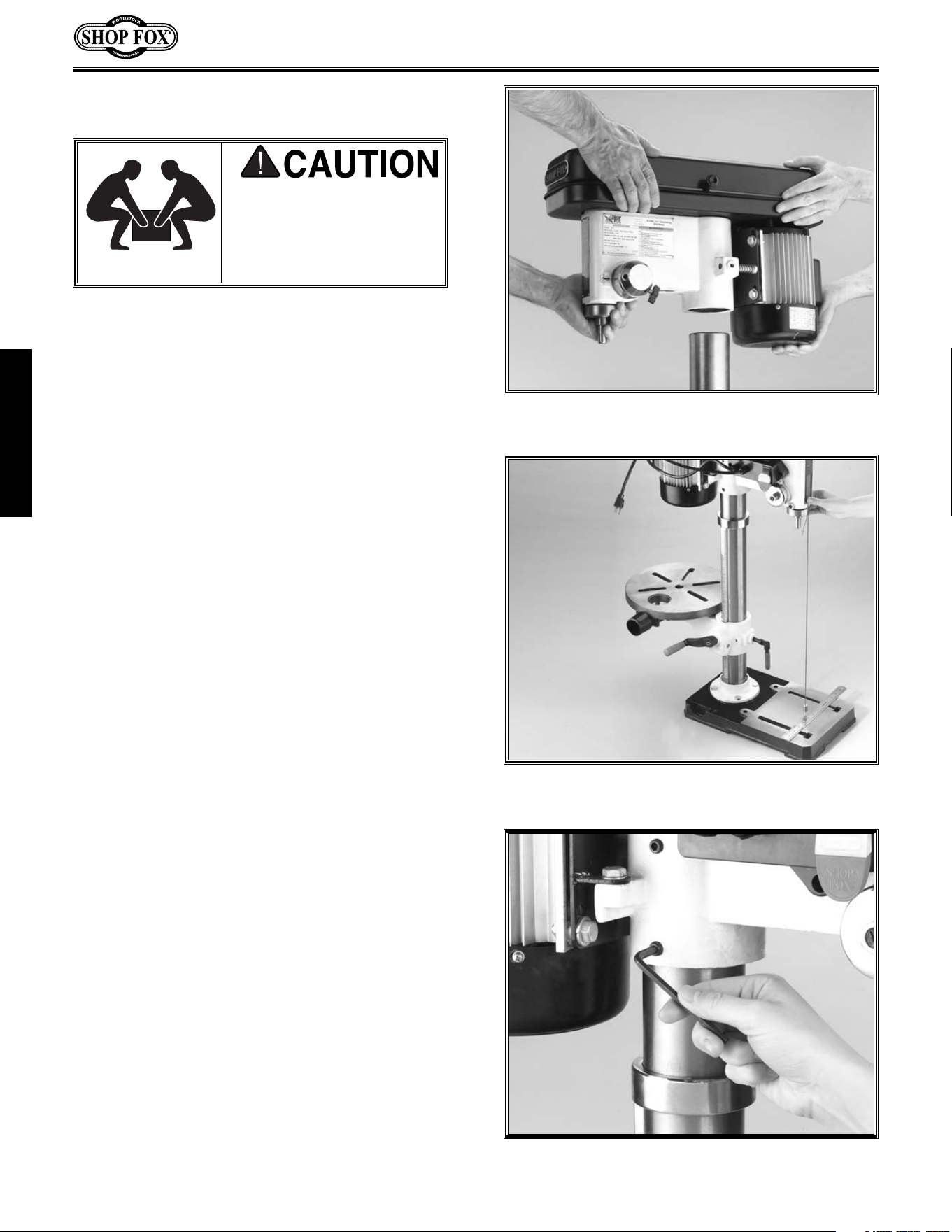
HeadStock
1. The bottom of the headstock has a pocket
for inserting the column. Position the pock-
et over the column, as in
Figure 15.
Allow
the headstock to slide down until it stops
(approximately 3
1
⁄2").
2. Align the headstock directly over the foot of
the base by using a plumb bob. Lay a mea-
suring tape or ruler across the drill press
base and find its center. Suspend the plumb
line from the center of the headstock label
as in Figure 16 and lower the bob until it is
near the tape/ruler. Adjust headstock from
side to side until the tip is equidistant from
the left and right sides.
3. Tighten the two setscrews in Figure 17 to
secure the headstock to the column.
The headstock repre-
sents a heavy load. Seek
assistance before begin-
ning this step.
Figure 15.
Align pocket in headstock with column.
Figure 16.
Align headstock with base.
Figure 17.
Tighten setscrews to secure headstock.
ASSEMBLY
-13-
Handles
Three handles are supplied with your new
Oscillating Drill Press. Thread them into the hub
as in Figure 20.
Figure 20.
Spindle handle installation.
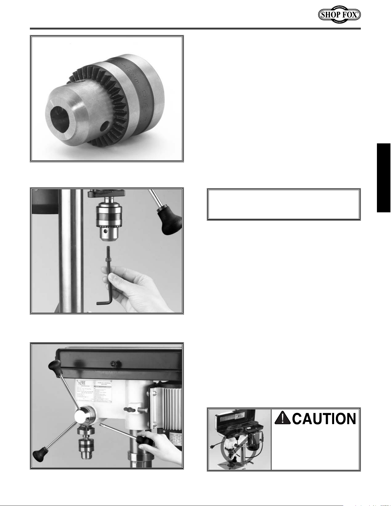
Drill Chuck
Figure 19.
Securing drill chuck with screw.
Figure 18.
Jaws adjusted inside chuck body.
The drill chuck is attached to the drill spindle by
means of matched tapers and screw. To mount
the drill chuck to the spindle, carefully follow
the instructions below:
1. The drill chuck and spindle must be thor-
oughly cleaned before assembly. It is rec-
ommended that mineral spirits be used for
this task. Refer to the safety warnings on
the container. Failure to clean the mating
surfaces may result in separation and wear.
2. Use the chuck key provided to adjust the
jaws of the chuck until they are well inside
the drill chuck body.
Figure 18.
3. Place the drill chuck on the spindle. Insert
the Allen
®
head cap screw into the hole of
the drill chuck as in
Figure 19. Tighten the
screw.
The drill chuck should be seated
securely on the spindle at this time and
should be checked for looseness. If the
chuck fails to remain secure on the spindle,
repeat step 1 and 2.
Unplug machine and
remove handles before
using the oscillating fea-
ture. Handles swing dur-
ing oscillating operation.
ASSEMBLY
DO NOT use a hammer on the drill chuck to
seat it onto the spindle. Damage will occur to
the oscillating mechanism.
-14-
Speed Change
ADJUSTMENTS
Unplug the drill press before changing speeds.
The Oscillating Drill Press has 12 speeds ranging
from 250 to 3050 RPM. There is a speed chart
located under the belt guard and one on the fol-
lowing page. Refer to the speed chart while
reading these instructions.
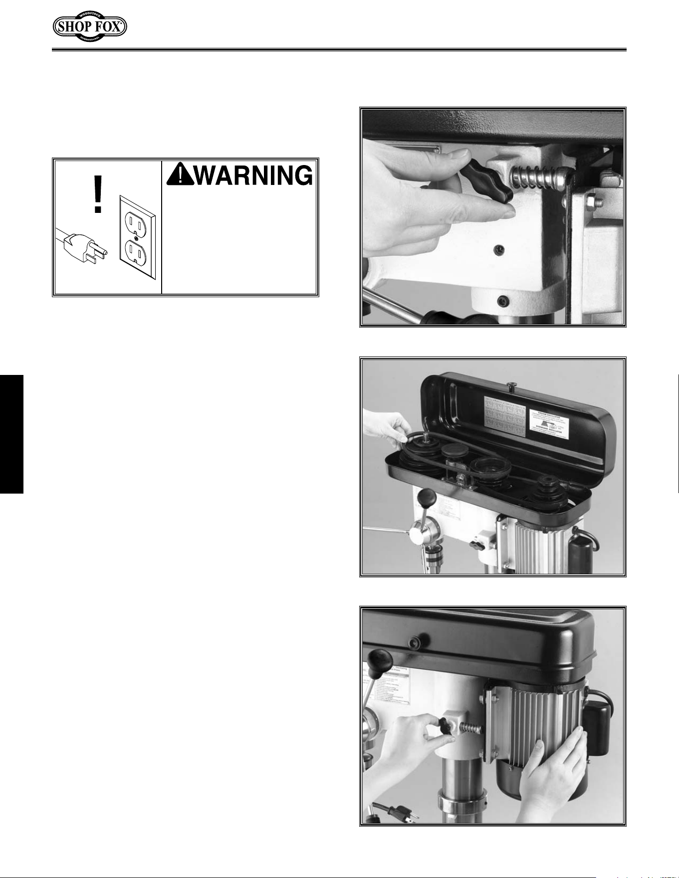
1. Loosen the belt tension lock knob.
Figure 21.
2. The motor is now free to move and can be
pulled toward the front of the drill press.
This will take tension off the V-belts.
3. Locate the desired speed on the chart and
move the V-belts to the desired V-grooves
on the motor, idler and spindle pulleys.
Figure 22.
4. Push the motor toward the back of the
headstock, the motor support rod is spring
loaded and will follow the motor.
Figure
23.
Tighten the lock knob.
5. Close the cover. The motor will not start
until the cover is closed.
Figure 21. Loosening lock knob
Figure 22. Adjusting belt to desired speed.
Figure 23. Push motor toward back of machine.
Unplug the drill press
before changing speeds
to avoid accidental start
up. Failure to do this may
result in serious personal
injury.
ADJUSTMENTS
-15-
Spindle Adjustments
Your new drill press comes fitted with a depth
stop for use when drilling. Follow the instruc-
tions below for use.
1. Loosen the depth collar lock knob. Figure
24.
2. Rotate the depth collar to the desired depth
indicated by the scale on the collar. Secure
the collar with the lock knob.
3. Test the depth stop by measuring how far
the spindle actually moves when the han-
dles are rotated. Figure 25. Make adjust-
ment using step 1 and step 2 if needed.
The depth stop for drilling must be adjusted
before using the oscillating feature. If the
depth stop is left adjusted for a shallow hole,
damage will occur to the oscillating mecha-
nism. Loosen the depth collar lock knob and
rotate the collar until the scale indicates 3".
Tighten the lock knob.
More About Speed Change
Figure 24. Loosening collar lock knob.
Figure 25. Actual stop depth being measured.
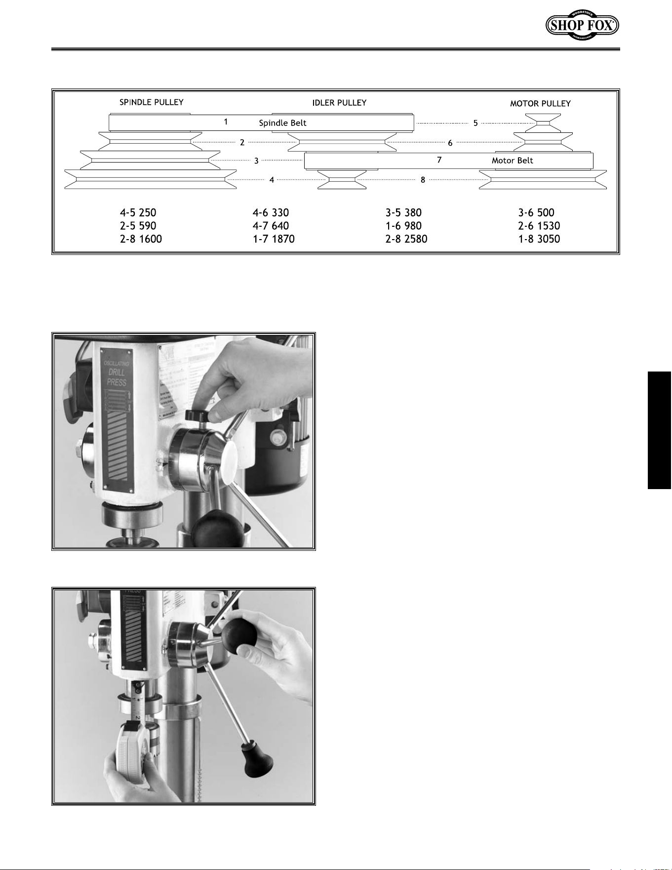
The speed chart above is included to help illustrate belt changes necessary to produce a desired speed.
Select the proper speed for the job at hand and find it on the speed chart above. Move the belts to the
indicated location on the chart. The belt setting in the example above shows the belt in the #1 spindle
pulley position and the belt is in the #7 motor pulley location. This will produce a speed of 1,870 RPM.
ADJUSTMENTS
-16-
Oscillating Feature
One of the great features of the W1668 Drill
Press is its capability for oscillating sanding. The
drill press can be converted from drilling opera-
tions to sanding operations in just a few steps.
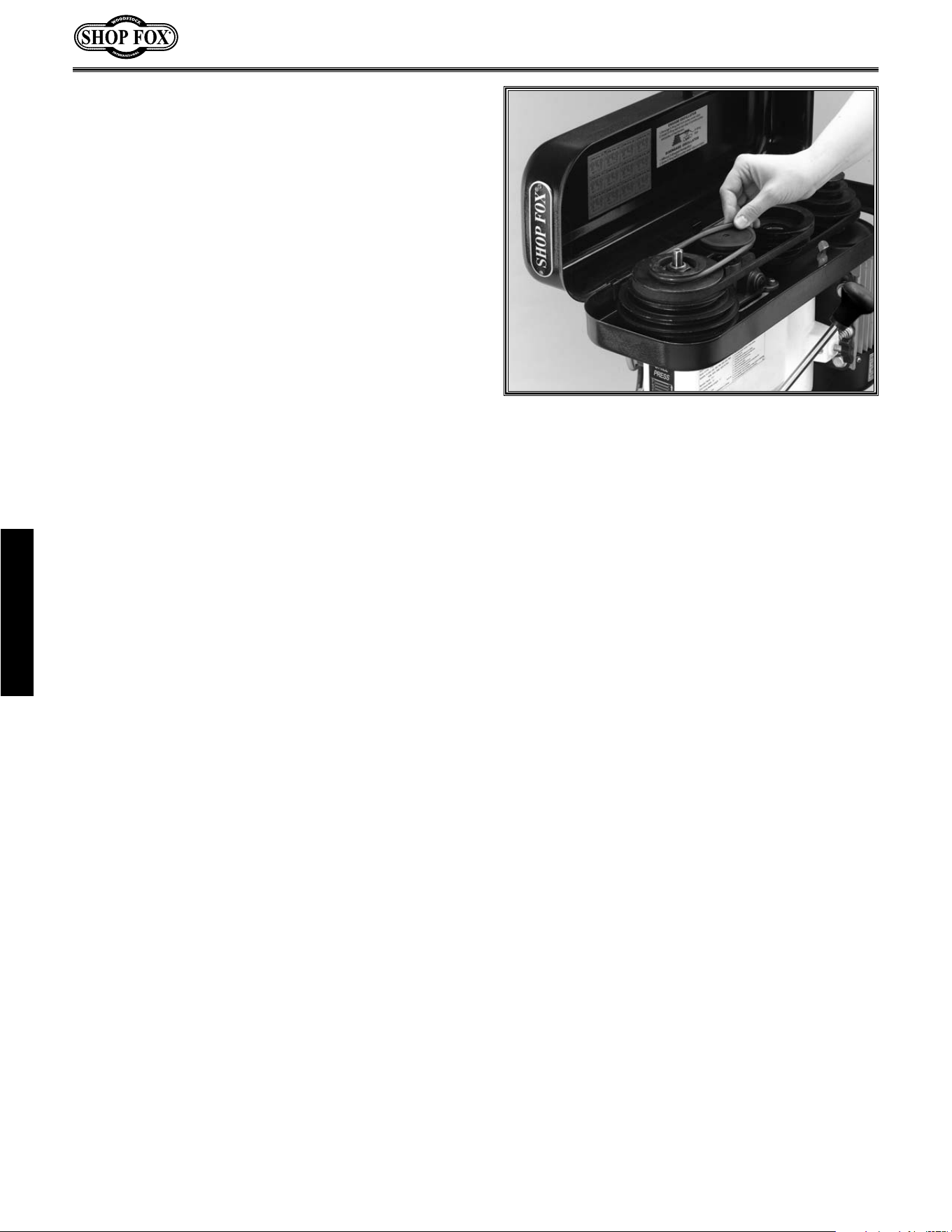
1. Unplug the drill press and remove the
spindle handles.
2. Install the round rubber belt onto the top
groove in the spindle pulley and the oscil-
lating pulley located between the idler pul-
ley and the spindle pulley. The belt will
stretch for this purpose.
Figure 22.
4. Remove the 3 spindle handles. If left in
place, the operator may be struck by them
while the spindle travels up and down.
3.
Close the cover. The motor will not start
until the cover is closed.
4. Loosen the knob for depth stop.
If the depth stop is left adjusted for a shallow
hole, damage will occur to the oscillating
mechanism. Check and adjust depth stop
before using oscillating feature.
Figure 26. Stretch the belt to fit on pulleys.
ADJUSTMENTS
-17-
Table Adjustments
The table can be adjusted to accommodate
height of materials to be sanded or drilled. To
adjust:
1. Loosen the table support bracket lock knob.
Turn the table hand crank to raise or lower
the table. Figure 27.
2. The table can be adjusted out of the way so
the base of the drill press may be used to
support the workpiece for drilling opera-
tions only. Loosen the table lock knob and
pivot the table to the back side of the col-
umn.
Figure 28.
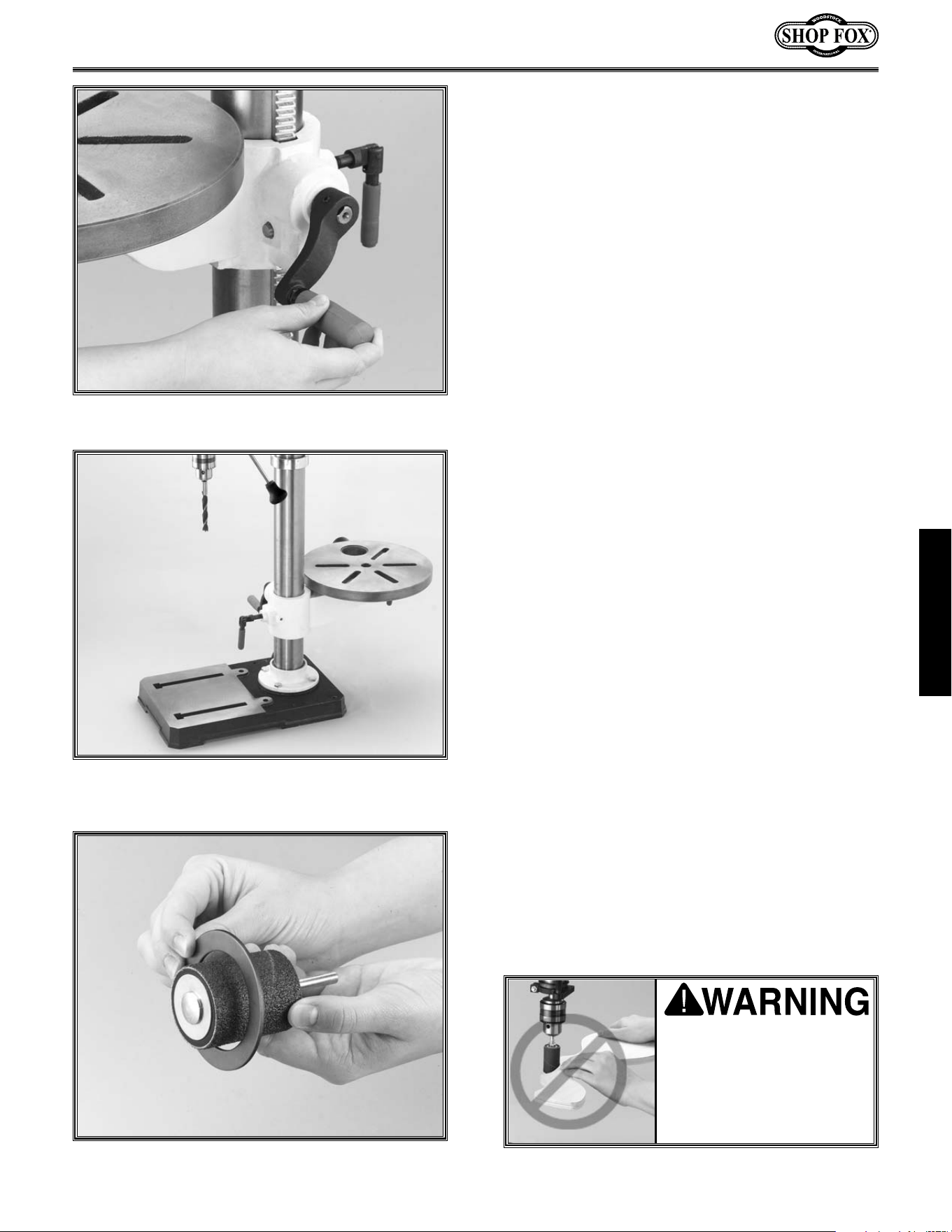
3. The drill press is supplied with 4 table
inserts. Always choose the insert whose
opening is only slightly bigger than the sand-
ing drum chosen.
Figure 29.
For drilling,
always use the table insert with the small-
est opening unless using a vise. Install the
chosen table insert into the pocket provided
in the top of the table.
4. The table should be adjusted so the opening
in the installed table insert is centered to
the drill bit or sanding drum. Loosen the
table and pivot the table until the bit or
drum is centered with the hole.
A table insert is not needed when sanding with
a 2" drum.
Sanding Tip: To use all of the grit on the paper,
adjust the table height as the paper wears.
When the thickness of the workpiece does not
allow much table movement, remove the drum
from the sanding spindle, turn it end for end and
replace it on the sanding spindle.
Figure 27. Use handle to adjust table height.
Figure 29. Checking drum size and table insert.
Figure 28. Table adjusted behind column.
Never sand or drill with-
out the table for support
and workpiece properly
secured. Serious per-
sonal injury may occur.
ADJUSTMENTS
Always wear safety glass-
es when operating drill
press. Failure to comply
may result in serious per-
sonal injury.
-18-
OPERATIONS
Once assembly is complete and adjustments are
done to your satisfaction, you are ready to test
run the machine.
Make sure the starting switch is off. The paddle
is down when off. Make sure all the fasteners
and lock handles are tight. Plug in the power
cord. Pull the START paddle. Make sure that your
finger is poised over the paddle,as in
Figure 30,
just in case there is a problem. The drill press
should run smoothly, with little or no vibration or
rubbing noises. Strange or unnatural noises
require you to stop the machine, investigate and
correct before continuing. If source of unusual
noise or vibration is not readily apparent, con-
tact our service department for help at 360-734-
3482 or: [email protected].
Test Run
DO NOT attempt to inves-
tigate or adjust the
machine while it is run-
ning. Wait until the
machine is turned off,
unplugged and all work-
ing parts have come to a
stop before proceeding!
Figure 30. Hand poised over stop paddle.
OPERATIONS
Installing the sanding drum spindle is identical to installing a drill bit. However, it is important to install
the paper and drum before installing the spindle into the drill chuck. See your local retailer for drums
and paper.
-
19-
Care must be taken to secure the bit firmly in
the drill chuck. When changing bits, proceed as
follows:
1. Disconnect the machine from the power
source.
2. Open the chuck wide enough to accept a
drill bit.
3. Install the bit so the chuck jaws will grab as
much of the bit shank as it can.
Figure 31.
Do not allow the chuck to grab the fluted
body of the drill bit. Make sure small drill
bits do not get trapped between the edges
of two jaws.
Drill Changes
Figure 32. Chuck key engaged.
Figure 31. Installing bit.
4. Tighten the chuck with the chuck key using
any of the three key end locations.
Figure
32.
5. Remove the chuck key and reconnect to the
power source.
6. Reverse steps to remove the drill bit.
Never drill or sand with-
out the table for support
and workpiece properly
secured. Serious per-
sonal injury may occur.
OPERATIONS
-20-
MAINTENANCE
Lubrication
Since all bearings are shielded and permanently
lubricated, simply leave them alone until they
need to be replaced. Do not lubricate them.
For other items on this machine, such as the
quill, table and column, an occasional shot of
light machine oil is all that is necessary. Before
applying lubricant, clean off sawdust and metal
chips.
Your goal is to achieve adequate lubrication.
Too much lubrication will attract dirt and saw-
dust. Various parts of your machine could loose
their freedom of movement as a result.
Regular periodic maintenance on your Model
W1668 Oscillating Drill Press will ensure its opti-
mum performance. Make a habit of inspecting
your drill press each time you use it. Check for
the following conditions and repair or replace
when necessary.
1. Loose mounting bolts.
2. Worn switch.
3. Worn or damaged cords and plugs.
4. Damaged V-belt.
5. Any other condition that could hamper the
safe operation of this machine.
General
Table And Base
Tables can be kept rust-free with regular appli-
cations of products like Boeshield
®
T-9. For long
term storage you may want to consider products
like Kleen Bore's Rust Guardit™.
Disconnect power to the
machine when perform-
ing any maintenance or
repairs. Failure to do this
may result in serious per-
sonal injury.
MAINTENANCE
-21-
The following pages contain general machine
data, parts diagrams/lists and warranty/return
information for your Shop Fox
®
Model W1668
Drill Press.
If you need parts or help in assembling your
machine, or if you need operational informa-
tion, we encourage you to call our Service
Department. Our trained service technicians will
be glad to help you.
If you have comments dealing specifically with
this manual, please write to us using the address
in the General Information. The specifications,
drawings, and photographs illustrated in this
manual represent the Model W1668 as supplied
when the manual was prepared. However, due
to Woodstock International, Inc.’s policy of con-
tinuous improvement, changes may be made at
any time with no obligation on the part of
Woodstock International, Inc. Whenever possi-
ble, though, we send manual updates to all own-
ers of a particular tool or machine that have reg-
istered their purchase with our warranty card.
Should you receive one, add the new informa-
tion to this manual and keep it for reference.
We have included some important safety mea-
sures that are essential to this machine’s opera-
tion. While most safety measures are generally
universal, we remind you that each workshop is
different and safety rules should be considered
as they apply to your specific situation.
We recommend you keep this manual for com-
plete information regarding Woodstock
International, Inc.’s warranty and return policy.
Should a problem arise, we recommend that you
keep proof of purchase with your manual. If you
need additional technical information relating
to this machine, or if you need general assis-
tance or replacement parts, please contact the
Service Department at 1-360-734-3482.
Additional information sources are necessary to
realize the full potential of this machine. Trade
journals, woodworking magazines, and your
local library are good places to start.
The Model W1668 was specifically designed for
drilling and drum sanding operations. DO NOT
MODIFY AND/OR USE THIS DRILL PRESS FOR
ANY OTHER PURPOSE. MODIFICATIONS OR
IMPROPER USE OF THIS TOOL WILL VOID THE
WARRANTY. If you are confused about any
aspect of this machine, DO NOT use it until you
have answered all your questions.
CLOSURE
As with all power tools, there is danger asso-
ciated with the Model W1668 Drill Press. Use
the tool with respect and caution to lessen
the possibility of mechanical damage or
operator injury. If normal safety precautions
are overlooked or ignored, injury to the
operator or others in the area is likely.
Keep your shop “Kid
Safe”. Always remove
the switch safety key
when drill press is not in
use. Serious injury may
occur.
CLOSURE
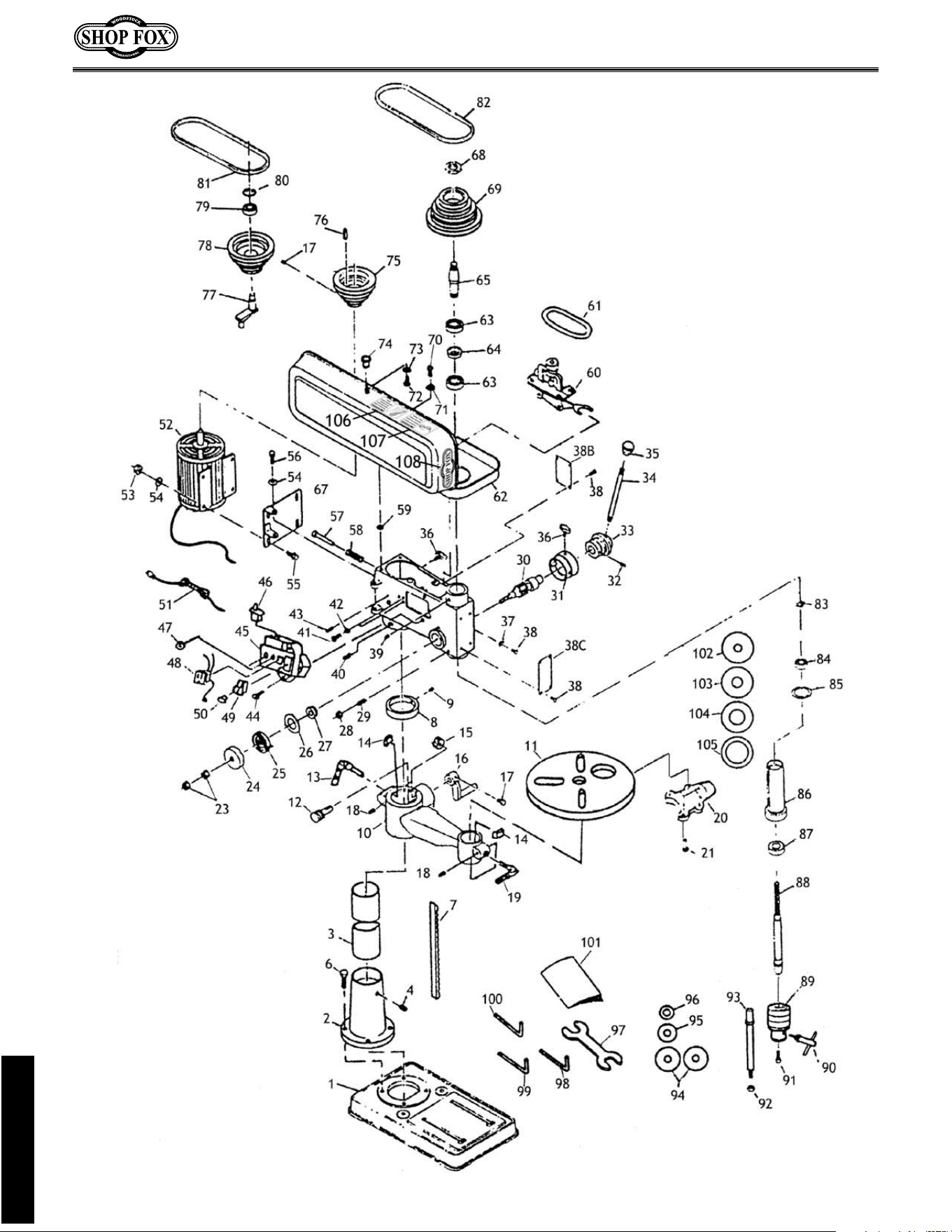
PARTS

-23-
55 XPB07M HEX BOLT M8-1.25 X 25
56 XPB09M HEX BOLT M8-1.25 X 20
57 X1668057 PUSH ROD
58 X1668058 SPRING
59 X1668059 RUBBER WASHER
60 X1668060 OSCILLATING MECHANISM
61 X1668061 ROUND DRIVE BELT
62 X1668062 PULLEY COVER
63 XP6203 BALL BEARING 6203
64 X1668064 COLLAR
65 X1668065 INTERNAL SPLINE SLEEVE
67 X1668067 MOTOR MOUNT
68 X1668068 LOCK NUT
69 X1668069 SPINDLE PULLEY
70 XPS31M PHLP HD SCR M6-1.0 X 20
71 XPLW03M LOCK WASHER 6MM
72 XPS09M PHLP HD SCR M5-0.8 X 10
73 XPW02M FLAT WASHER 5MM
74 X1668074 KNOB
75 X1668075 IDLER PULLEY
76 X1668076 KEY
77 X1668077 IDLER ARM
78 X1668078 IDLER PULLEY
79 XP6202 BALL BEARING 6202
80 X1668080 RETAINING RING
81 XPW01M MOTOR V-BELT
82 X1668082 SPINDLE V-BELT
83 X1668083 RETAINING RING
84 XP6201 BALL BEARING 6201
85 X1668085 RUBBER WASHER
86 X1668086 QUILL
87 XP6204 BALL BEARING 6204
88 X1668088 SPINDLE
89 X1668089 DRILL CHUCK
90 X1668090 CHUCK KEY
91 XPSB15M CAP SCREW M5-0.8 X 20
92 XPN03M HEX NUT M8-1.25
93 X1668093 MANDREL
94 X1668094 MANDREL WASHER 1
3
⁄
4"
95 X1668095 MANDREL WASHER
7
⁄8"
96 X1668096 MANDREL WASHER
3
⁄4"
97 X1668097 OPEN END WRENCH
98 XPW03M 3mm ALLEN
®
WRENCH
99 XPW04M 4mm ALLEN
®
WRENCH
100 XPW04M 5mm ALLEN
®
WRENCH
101
X1667MANUAL
MANUAL
102 X1668102 TABLE INSERT
5
⁄8"
103 X1668103 TABLE INSERT 1"
104 X1668104 TABLE INSERT 1
3
⁄8"
105 X1668105 TABLE INSERT 1
7
⁄
8"
106 X1668106
LONG HAIR SAFETY LABEL
107 X1668107 GLASSES SAFETY LABEL
108 X1668108 MACHINE LABEL
01 X1668001 BASE
02 X1668002 COLUMN FLANGE
03 X1668003 COLUMN
04 X1668004 TABLE BRACKET
06 XPB32M HEX BOLT M10-1.5 X 25
07 X1668007 RACK
08 X1668008 COLUMN RING
09 XPSS01M SET SCREW M6-1.0 X 10
10 X1668010 TABLE BRACKET
11 X1668011 TABLE
12 X1668012 WORM PINION
13 X1668013 LOCK HANDLE M10
14 X1668014 LOCK SHOE
15 X1668015 WORM GEAR
16 X1668016 LIFT HANDLE
17 XPSS01M SET SCREW M6-1.0 X 10
18 XPSS22M SET SCREW M4-0.7 X 12
19 X1668019 LOCK HANDLE M8
20 X1668020 DUST PORT
21 XPS33M PHLP HD SCR M4-0.7 X 22
22 X1668022 HEAD CASTING
23 XPN02M HEX NUT M10-1.5
24 X1668016 SPRING COVER
25 X1668025 RETURN SPRING
26 X1668026 SPRING WASHER
27 X1668027 BUSHING
28 XPN01M HEX NUT M6-1.0
29 X1668029 SPECIAL SET SCREW
30 X1668030 FEED SHAFT
31 X1668031 DEPTH COLLAR
32 XPRP07M ROLL PIN 6MM X 20
33 X1668033 FEED COLLAR
34 X1668034 HANDLE BAR
35 X1668035 KNOB
36 X1668036 LOCK KNOB
37 X1668037 POINTER
38 X1668038 RIVET
38C X1668038C DEPTH CHART
39 XPSS16M SET SCREW M8-1.25 X 10
40 XPSS13M SET SCREW M10-1.5 X 12
41 XPS32M PHLP HD SCR M4-0.7 X 10
42 X1668042 STAR WASHER
43 XPRP07M ROLL PIN 6MM X 20
44 XPS32M PHLP HD SCR M4-0.7 X 10
45 X1668045 SWITCH BOX
46 X1668046 LIMIT SWITCH
48 X1668048 STRAIN RELIEF
49 X1668049 SAFETY SWITCH
50 X1668050 SWITCH KEY
51 X1668051 POWER CORD
52 X1668052 MOTOR
3
⁄4 HP
53 XPN03M HEX NUT M8-1.25
54 XPW01M FLAT WASHER M8
REF PART # DESCRIPTION
REF PART # DESCRIPTION
PARTS

-24-
NOTES:

CUT ALONG DOTTED LINE
10. What stationary woodworking tools do you own? Check all that apply.
___Air Compressor ___Panel Saw
___Band Saw ___Planer
___Drill Press ___Power Feeder
___Drum Sander ___Radial Arm Saw
___Dust Collector ___Shaper
___Horizontal Boring Machine ___Spindle Sander
___Jointer ___Table Saw
___Lathe ___Vacuum Veneer Press
___Mortiser ___Wide Belt Sander
___Other__________________________________________________
11. Which benchtop tools do you own? Check all that apply.
___1" x 42" Belt Sander ___6" - 8" Grinder
___5" - 8" Drill Press ___Mini Lathe
___8" Table Saw ___10" - 12" Thickness Planer
___8" - 10" Bandsaw ___Scroll Saw
___Disc/Belt Sander ___Spindle/Belt Sander
___Mini Jointer ___Power Tools
___Other__________________________________________________
12. Which portable/hand held power tools do you own? Check all that apply.
___Belt Sander ___Orbital Sander
___Biscuit Joiner ___Palm Sander
___Circular Saw ___Portable Planer
___Detail Sander ___Saber Saw
___Drill/Driver ___Reciprocating Saw
___Miter Saw ___Router
___Other__________________________________________________
13. What machines/supplies would you like to see?
___12" Table Saw ___Radial Arm Saw
___12" Jointer ___Panel Saw
___Combination Planer/Jointer ___Brass Hardware
___Paint & Finnish Supplies ___Lumber
___Contractor’s Supplies
_____other________________________________________________
14. What new accessories would you like Woodstock International to carry?
_________________________________________________________
_________________________________________________________
15. Do you think your purchase represents good value?
___Yes ___No
16. Would you recommend Shop Fox
®
products to a friend?
___Yes ___No
17. Comments:_________________________________________________
__________________________________________________________
_____________________________________________________________
_____________________________________________________________
____________________________________________________
1. Where did you purchase your Shop Fox
®
machine?
Store?______________________City?______________________
2. How did you first learn about us?
___Advertisement ___Friend
___Mail order Catalog ___Local Store
___World Wide Web Site
___Other__________________________________________________
3. Which of the following magazines do you subscribe to.
___American Woodworker ___Today’s Homeowner
___Cabinetmaker ___WOOD
___Family Handyman ___Wooden Boat
___Fine Homebuilding ___Woodshop News
___Fine Woodworking ___Woodsmith
___Home Handyman ___Woodwork
___Journal of Light Construction ___Woodworker
___Old House Journal ___Woodworker’s Journal
___Popular Mechanics ___Workbench
___Popular Science ___American How-To
___Popular Woodworking
___Other__________________________________________________
4. Which of the following woodworking/remodeling shows do you watch?
___Backyard America ___The New Yankee Workshop
___Home Time ___This Old House
___The American Woodworker ___Woodwright’s Shop
___Other__________________________________________________
5. What is your annual household income?
___$20,000-$29,999 ___$60,000-$69,999
___$30,000-$39,999 ___$70,000-$79,999
___$40,000-$49,999 ___$80,000-$89,999
___$50,000-$59,999 ___$90,000 +
6. What is your age group?
___20-29 ___50-59
___30-39 ___60-69
___40-49 ___70 +
7. How long have you been a woodworker?
___0 - 2 Years ___8 - 20 Years
___2 - 8 Years ___20+ Years
8. How would you rank your woodworking skills?
___Simple ___Advanced
___Intermediate ___Master Craftsman
9. How many Shop Fox
®
machines do you own? _____________
WARRANTY CARD
Name __________________________________________________________________________________________
Street __________________________________________________________________________________________
City ____________________________________________________________________State________Zip_________
Phone Number_______________________E-Mail_______________________FAX________________________
MODEL #________________________________________________________________________________________
The following information is given on a voluntary basis and is strictly confidential.

TAPE ALONG EDGES--PLEASE DO NOT STAPLE
FOLD ALONG DOTTED LINE
FOLD ALONG DOTTED LINE
WOODSTOCK INTERNATIONAL, INC.
P.O. BOX 2309
BELLINGHAM, WA 98227-2309
Place
Stamp
Here