
OWNER'S MANUAL
(FOR MODELS MANUFACTURED SINCE 3/17)
MODEL W1843
KNIFE BLADE SANDER/BUFFER
Phone: (360) 734-3482 • Online Technical Support: [email protected]
COPYRIGHT © MAY, 2017 BY WOODSTOCK INTERNATIONAL, INC.
WARNING: NO PORTION OF THIS MANUAL MAY BE REPRODUCED IN ANY SHAPE OR FORM WITHOUT
THE WRITTEN APPROVAL OF WOODSTOCK INTERNATIONAL, INC.
#18917JH Printed in Taiwan

This manual provides critical safety instructions on the proper setup,
operation, maintenance, and service of this machine/tool. Save this
document, refer to it often, and use it to instruct other operators.
Failure to read, understand and follow the instructions in this manual
may result in fire or serious personal injury—including amputation,
electrocution, or death.
The owner of this machine/tool is solely responsible for its safe use.
This responsibility includes but is not limited to proper installation in
a safe environment, personnel training and usage authorization,
proper inspection and maintenance, manual availability and compre-
hension, application of safety devices, cutting/sanding/grinding tool
integrity, and the usage of personal protective equipment.
The manufacturer will not be held liable for injury or property
damage from negligence, improper training, machine modifications or
misuse.
Some dust created by power sanding, sawing, grinding, drilling, and
other construction activities contains chemicals known to the State of
California to cause cancer, birth defects or other reproductive harm.
Some examples of these chemicals are:
• Lead from lead-based paints.
• Crystalline silica from bricks, cement and other masonry products.
• Arsenic and chromium from chemically-treated lumber.
Your risk from these exposures varies, depending on how often you
do this type of work. To reduce your exposure to these chemicals:
Work in a well ventilated area, and work with approved safety equip-
ment, such as those dust masks that are specially designed to filter
out microscopic particles.

SET UPELECTRICAL MAINTENANCE
SERVICE PARTS
OPERATIONS
SAFETYINTRODUCTION
USE THE QUICK GUIDE PAGE LABELS TO SEARCH OUT INFORMATION FAST!
INTRODUCTION......................................2
Contact Info ....................................... 2
Manual Accuracy .................................. 2
Machine Data Sheet .............................. 3
Identification ..................................... 5
SAFETY................................................6
Standard Machinery Safety Instructions ...... 6
Additional Safety for Belt Sanders ............ 8
Additional Safety for Buffing Systems ........ 9
ELECTRICAL........................................ 10
Circuit Requirements .......................... 10
Grounding Requirements ...................... 11
Extension Cords ................................ 11
SETUP............................................... 12
Unpacking ....................................... 12
Items Needed for Setup ....................... 12
Hardware Recognition Chart ................. 13
Inventory ........................................ 14
Machine Placement ............................ 15
Cleaning Machine ............................... 15
Bench Mounting................................. 16
Assembly ......................................... 17
Test Run .......................................... 21
OPERATIONS....................................... 22
General .......................................... 22
Sanding Belt ..................................... 23
Belt Sanding ..................................... 26
Buffing & Polishing Setup ..................... 28
Buffing ........................................... 29
Buffing Compound Selection ................. 30
Buffing Wheel Selection ....................... 31
ACCESSORIES....................................... 32
Sander/Buffer Accessories .................... 32
MAINTENANCE..................................... 34
General .......................................... 34
Cleaning & Protecting ......................... 34
Lubrication ...................................... 34
SERVICE............................................. 35
Troubleshooting ................................. 35
Electrical Safety Instructions ................. 37
Wiring Diagram ................................. 38
PARTS............................................... 39
Motor Assembly ................................. 39
Sanding Assembly............................... 40
Labels & Cosmetics ............................ 42
WARRANTY......................................... 45
Contents
-2-
Model W1843 (For Machines Mfd. Since 3/17)
INTRODUCTION
INTRODUCTION
We are proud to provide a high-quality owner’s
manual with your new machine!
We
made every effort to be exact with
the
instructions, specifications, drawings, and pho-
tographs contained inside. Sometimes we make
mistakes, but our policy of continuous improve-
ment
also means that sometimes. the
. machine.
you.receive.will.be.slightly.different.than.what.
is.shown.in.the.manual
.
If you find this to be the case, and the difference
between the manual and machine leaves you
confused about a procedure
,
check our website
for an updated version. W
e post current
manuals
and
manual updates for free
on our website at
www.
woodstockint.com.
Alternatively, you can call our Technical Support
for help. Before calling, make sure you write
down the
Manufacture.Date and Serial.Number
from the machine ID label (see below). Also, if
available, have a copy of your original.purchase.
receipt on hand. This information is required for
all Tech Support calls.
MODEL XXXX
MACHINE NAME
Motor:
Specification:
Specification:
Specification:
Specification:
Weight:
Specifications
To reduce risk of serious personal injury when using this
machine:
1. Read & understand owner’s manual before operating.
2. Always wear approved eye protection and respirator.
3. Only plug power cord into a grounded outlet.
4. Only use this machine to collect wood dust/chips—never
use to collect glass, metal, liquids, asbestos, silica,
animal parts, biohazards, burning material/ashes, etc.
5. Always disconnect power before servicing or cleaning.
6. Do not expose to rain or wet areas.
7. Keep hands, long hair, and loose clothing away from
inlet.
8. Never leave machine unattended while it is running.
9. Do not use if cord/plug becomes damaged—promptly
repair and protect cord from future damage.
10. Do not use without dust bag or filters in place.
11. Always wear a respirator when emptying bags.
12. Prevent unauthorized use by children or untrained users.
Date
Serial Number
Manufactured for Woodstock in Taiwan
WARNING!
Manufacture
Date
Serial Number
Ma n ual.Accuracy
We are committed to customer satisfaction. If
you have any questions or need help, use the
information below to contact us.
IMPORTANT:.Before.contacting,.please.get.the.
original.purchase. receipt,. serial.number,. and.
manufacture.date.of.your.machine..This.infor-
mation. is. required. for. all. Technical. Support.
calls.and.it.will.help.us.help.you.faster..
Woodstock International Technical Support
Phone: (360) 734-3482
Email: [email protected]
We want your feedback on this manual. What did
you like about it? Where could it be improved?
Please take a few minutes to give us feedback.
Technical Documentation Manager
P.O. Box 2309
Bellingham, WA 98227
Email: [email protected]
Contact.Info

-3-
Model W1843 (For Machines Mfd. Since 3/17)
INTRODUCTION
Product Dimensions
Weight ................................................................................................................... 105 lbs.
Width (side-to-side) x Depth (front-to-back) x Height ........................................... 39 x 29-1/2 x 39 in.
Footprint (Length x Width) .................................................................................. 10 x 16-1/2 in.
Shipping Dimensions
Carton #1
Type ............................................................................................................ Cardboard
Content ........................................................................................................... Machine
Length x Width x Height ..............................................................................31 x 17 x 15 in.
Weight...............................................................................................................58 lbs.
Carton #2
Type ............................................................................................................ Cardboard
Content ......................................................................................................Sanding Arm
Length x Width x Height ............................................................................... 27 x 11 x 9 in.
Weight...............................................................................................................54 lbs.
Electrical
Power Requirement.............................................................................. 110V, Single-Phase, 60 Hz
Full-Load Current Rating .................................................................................................. 14A
Minimum Circuit Size ....................................................................................................... 20A
Connection Type .................................................................................................. Cord & Plug
Power Cord Included ........................................................................................................ Yes
Power Cord Length ........................................................................................................ 5 ft.
Power Cord Gauge ......................................................................................................16 AWG
Plug Included ................................................................................................................. Ye s
Included Plug Type ................................................................................................. NEMA 5-15
Switch Type ........................................................................................................... Push/Pull
Motor
Main
Type ...................................................................................TEFC Capacitor-Start Induction
Horsepower .......................................................................................................... 1 HP
Phase .........................................................................................................Single-Phase
Amps ................................................................................................................... 14A
Speed ............................................................................................................ 1725 RPM
Power Transfer .............................................................................................. Direct Drive
Bearings ......................................................................... Shielded & Permanently Lubricated
MODEL W1843
KNIFE BELT SANDER/BUFFER
Model W1843 Machine Specifications, Page 1 of 2
© Woodstock International, Inc. • Phone #: (800) 840-8420 • Web: www.shopfox.biz
MACHINE
SPECIFICATIONS

-4-
Model W1843 (For Machines Mfd. Since 3/17)
INTRODUCTION
Main Specifications
Belt Info
Sanding Belt Width .................................................................................................. 2 in.
Sanding Belt Length .......................................................................................... 72 - 76 in.
Sanding Belt Speed............................................................................................ 4500 FPM
Belt Arm Tilt ................................................................................................. 0 - 90 deg.
Height Belt Arm Horizontal ................................................................................. 11-1/2 in.
Height Belt Arm Vertical ..........................................................................................39 in.
Belt Release Type ........................................................................................Quick Release
Drive Roller Type ........................................................................Cast Aluminum with Rubber
Drive Roller Length ................................................................................................. 7 in.
Drive Wheel Diameter .............................................................................................10 in.
Idler Roller Type ...............................................................................................Aluminum
Idler Roller Length .................................................................................................. 2 in.
Idler Roller Diameter ............................................................................................... 4 in.
Spindle Info
Spindle Speed .................................................................................................. 1725 RPM
Total Arbor Length .................................................................................................. 8 in.
Shaft Height ..................................................................................................... 7-1/2 in.
Wheel Info
Max Buffing Wheel Diameter .....................................................................................10 in.
Max Buffing Wheel Width ....................................................................................... 3/4 in.
Buffing Wheel Bore Size ......................................................................................... 5/8 in.
Platen Info
Platen Type .............................................................................................Graphite Coated
Platen Length ...................................................................................................9-1/4 in.
Platen Width ....................................................................................................1-7/8 in.
Construction
Base .............................................................................................................. Cast Iron
Frame ............................................................................................................Cast Iron
Paint Type/Finish ...................................................................................................Epoxy
Other Specifications
Country of Origin ....................................................................................................... Taiwan
Warranty ................................................................................................................. 2 Years
Approximate Assembly & Setup Time ................................................................................1 Hour
Serial Number Location ...............................................................................................ID Label
ISO 9001 Factory ..............................................................................................................No
Certified by a Nationally Recognized Testing Laboratory (NRTL) .....................................................No
Features
Left Arbor Accepts Buffing Wheels, Sanding Drums, or Flap Wheels
Belt Arm Can Be Tilted from 0–90 Degrees
All Ball-Bearing Construction
Cast-Iron Body
Model W1843 Machine Specifications, Page 2 of 2
-5-
Model W1843 (For Machines Mfd. Since 3/17)
INTRODUCTION
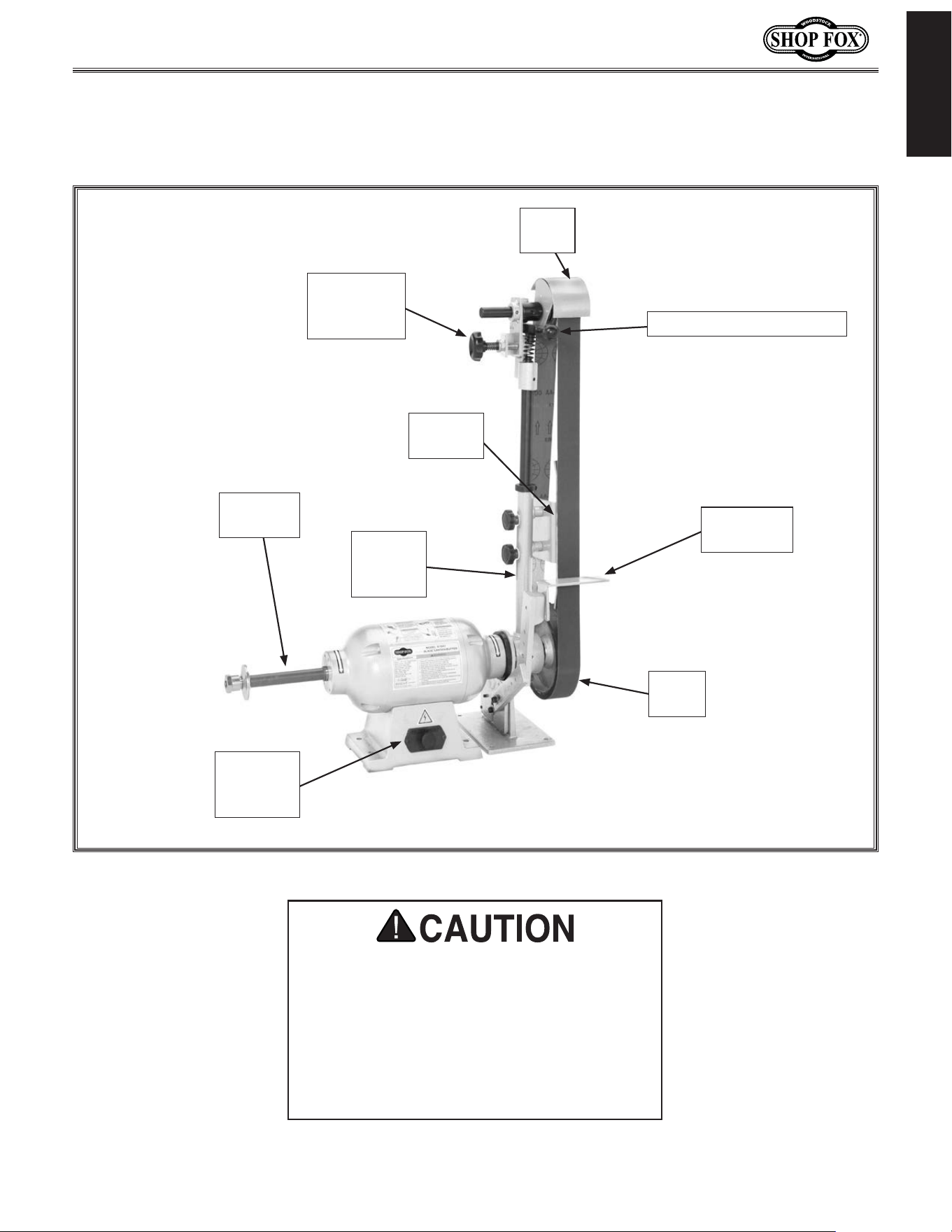
I dentification
Become familiar with the names and locations of the controls and features shown below to better
understand the instructions in this manual.
Figure 1. Model W1843 identification.
Belt Quick-Release Lever
Tracking
Adjustment
Knob
Sanding
Platen
Drive
Wheel
Adjustable
Tool Rest
Tilting
Sanding
Arm
Push/Pull
ON/OFF
Button
For Your Own Safety Read Instruction
Manual Before Operating the Sander
a) Wear eye and ear protection.
b) Support workpiece on worktable.
c) Maintain
1
⁄16" maximum clearance
between worktable and sandpaper.
d) Avoid kickback by sanding in accordance
with directional arrows.
Idler
Wheel
Auxiliary
Arbor

-6-
Model W1843 (For Machines Mfd. Since 3/17)
SAFETY
Indicates.a.potentially.hazardous.situation.which,.if.not.avoided,.
MAY.result.in.minor.or.moderate.injury.
Indicates.an.imminently.hazardous.situation.which,.if.not.avoided,.
WILL.result.in.death.or.serious.injury.
Indicates.a.potentially.hazardous.situation.which,.if.not.avoided,.
COULD.result.in.death.or.serious.injury.
This.symbol.is.used.to.alert.the.user.to.useful.information.about.
proper.operation.of.the.equipment.or.a.situation.that.may.cause.
damage.to.the.machinery.
NOTICE
SAFETY
OWNER’S.MANUAL..
Read and understand this
owner’s manual BEFORE using machine.
TRAINED.OPERATORS.ONLY..
Untrained operators
have a higher risk of being hurt or killed. Only
allow trained/supervised people to use this
machine. When machine is not being used,
disconnect power, remove switch keys, or
lock-out machine to prevent unauthorized
use—especially around children. Make
workshop kid proof!
DANGEROUS.ENVIRONMENTS..
Do not use
machinery in areas that are wet, cluttered,
or have poor lighting. Operating machinery
in these areas greatly increases the risk of
accidents and injury.
MENTAL.ALERTNESS.REQUIRED..
Full mental
alertness is required for safe operation of
machinery. Never operate under the influence
of drugs or alcohol, when tired, or when
distracted.
ELECTRICAL.EQUIPMENT.INJURY.RISKS..You can
be shocked, burned, or killed by touching live
electrical components or improperly grounded
machinery. To reduce this risk, only allow an
electrician or qualified service personnel to
do electrical installation or repair work, and
always disconnect power before accessing or
exposing electrical equipment.
DISCONNECT.POWER.FIRST..Always disconnect
machine from power supply BEFORE making
adjustments, changing tooling, or servicing
machine. This eliminates the risk of injury
from unintended startup or contact with live
electrical components.
EYE.PROTECTION..Always wear ANSI-approved
safety glasses or a face shield when operating
or observing machinery to reduce the risk of
eye injury or blindness from flying particles.
Everyday eyeglasses are not approved safety
glasses.
St and ard .Machinery.Safety.Instructions
For.Your.Own.Safety,
Read.Manual.Before.Operating.Machine
The. purpose. of. safet y. symbols. is. to. attract. your. attention. to. possible. hazardous. conditions.. This.
manual.uses.a.series.of.symbols.and.signal.words.intended.to.convey.the.level.of.importance.of.the.
safety. messages..The.progression.of.symbols.is.described.below..Remember.that.safety.messages.by.
themselves.do. not. eliminate.danger.and.are.not.a. substitute.for.proper.accident.prevention.mea-
sures—this. responsibility.is.ultimately.up.to.the.operator!
SAFETY
St and ard.Machinery.Safety.Instructions

-7-
Model W1843 (For Machines Mfd. Since 3/17)
SAFETY
WEARING.PROPER.APPAREL..Do not wear
clothing, apparel, or jewelry that can become
entangled in moving parts. Always tie back
or cover long hair. Wear non-slip footwear to
avoid accidental slips, which could cause loss
of workpiece control.
HAZARDOUS
.DUST..Dust created while using
machinery may cause cancer, birth defects,
or long-term respiratory damage. Be aware of
dust hazards associated with each workpiece
material, and always wear a NIOSH-approved
respirator to reduce your risk.
HEARING.PROTECTION..
Always wear hearing
protection when operating or observing
loud machinery. Extended exposure to this
noise without hearing protection can cause
permanent hearing loss.
REMOVE.ADJUSTING.TOOLS..
Tools left on
machinery can become dangerous projectiles
upon startup. Never leave chuck keys,
wrenches, or any other tools on machine.
Always verify removal before starting!
INTENDED.USAGE..
Only use machine for its
intended purpose—never make modifications
without prior approval from Woodstock
International. Modifying machine or using
it differently than intended will void the
warranty and may result in malfunction or
mechanical failure that leads to serious
personal injury or death!
AWKWARD.POSITIONS..
Keep proper footing and
balance at all times when operating machine.
Do not overreach! Avoid awkward hand
positions that make workpiece control difficult
or increase the risk of accidental injury.
CHILDREN.&.BYSTANDERS..
Keep children and
bystanders at a safe distance from the work
area. Stop using machine if they become a
distraction.
GUARDS.&.COVERS..
Guards and covers reduce
accidental contact with moving parts or flying
debris—make sure they are properly installed,
undamaged, and working correctly.
FORCING.MACHINERY..Do not force machine. It
will do the job safer and better at the rate for
which it was designed.
NEVER.STAND.ON.MACHINE..Serious injury may
occur if machine is tipped or if the cutting
tool is unintentionally contacted.
STABLE.MACHINE..Unexpected movement during
operation greatly increases risk of injury or
loss of control. Before starting, verify machine
is stable and mobile base (if used) is locked.
USE.RECOMMENDED.ACCESSORIES..Consult
this owner’s manual or the manufacturer for
recommended accessories. Using improper
accessories will increase risk of serious injury.
UNATTENDED.OPERATION..To reduce the risk
of accidental injury, turn machine OFF and
ensure all moving parts completely stop
before walking away. Never leave machine
running while unattended.
MAINTAIN.WITH.CARE..Follow all maintenance
instructions and lubrication schedules to
keep machine in good working condition. A
machine that is improperly maintained could
malfunction, leading to serious personal injury
or death.
CHECK.DAMAGED.PARTS..Regularly inspect
machine for any condition that may affect
safe operation. Immediately repair or replace
damaged or mis-adjusted parts before
operating machine.
MAINTAIN.POWER.CORDS..When disconnecting
cord-connected machines from power, grab
and pull the plug—NOT the cord. Pulling the
cord may damage the wires inside, resulting
in a short. Do not handle cord/plug with wet
hands. Avoid cord damage by keeping it away
from heated surfaces, high traffic areas, harsh
chemicals, and wet/damp locations.
EXPERIENCING.DIFFICULTIES..If at any time
you experience difficulties performing the
intended operation, stop using the machine!
Contact Technical Support at (360) 734-3482.

-8-
Model W1843 (For Machines Mfd. Since 3/17)
SAFETY
Additional.Safety.for.Belt.Sanders
Serious injury or death can occur from fingers, clothing, jewelry, or hair getting entangled in
moving
belt, spindle, or other components. Abrasion injuries can occur from touching moving
sandpaper with bare skin. Incorrect feeding of workpiece can lead to workpiece being thrown and
striking operator or bystanders with enough force to cause impact injuries. Long-term respiratory
damage can occur from using sander without proper use of a respirator. To reduce the risk of these
hazards, operator or bystanders MUST completely heed the hazards and warnings below.
WORKPIECE INSPECTION. Nails, staples, knots, or
other imperfections in workpiece can be dis-
lodged and thrown from sander at a high rate of
speed at people, or cause damage to sandpaper
or sander. Never sand stock that has embedded
foreign objects or questionable imperfections.
SANDPAPER CONDITION. Worn or damaged sand-
paper can fly apart and throw debris at opera-
tor, or aggressively grab workpiece, resulting in
subsequent injuries from operator loss of work-
piece control. Always inspect sandpaper before
operation and replace if worn or damaged.
IN-RUNNING NIP POINTS. The gap between mov-
ing sandpaper and fixed table/support creates
a pinch point for fingers or workpieces; the
larger this gap is, the greater the risk of fingers
or workpieces getting caught in it. Minimize this
risk by adjusting table/support to no more than
1
⁄16"
away from sandpaper. For spindle sanders,
always use the table insert that fits closest
diameter of installed drum.
WORKPIECE INTEGRITY. Sanding fragile work-
pieces can result in loss of control, resulting in
abrasion injuries, impact injuries, or damage
to sandpaper. Only sand solid workpieces that
can withstand power sanding forces. Make sure
workpiece shape is properly supported; avoid
sanding workpieces without flat bottom sur-
faces unless a jig is used to maintain support
and control when sanding force is applied.
SANDING DUST. Sanding creates large amounts of
dust that can lead to eye injury or respiratory
illness. Reduce your risk by always wearing
approved eye and respiratory protection when
using sander. Never operate without adequate
dust collection system in place and running.
Howe ver, dust collection is not a substitute for
using a respirator.
SANDPAPER DIRECTION. Feeding workpiece incor-
rectly can cause it to be thrown from machine,
striking operator or bystanders, or causing your
hands to slip into the moving sandpaper. To
reduce these risks, only sand against direction
of sandpaper travel, ensure workpiece is prop-
erly supported, and avoid introducing sharp
edges into moving sandpaper on the leading
side of the workpiece.
HAND PLACEMENT. Rotating sandpaper can
remove a large amount of flesh quickly. Always
keep hands away from sandpaper during opera-
tion. Never touch moving sandpaper on pur-
pose. Use a brush to clean table of sawdust
and chips.
FEEDING WORKPIECE. Forcefully jamming work-
piece into sanding surface could cause it to be
grabbed aggressively, pulling hands into sanding
surface. Firmly grasp workpiece in both hands
and ease it into sandpaper using light pressure.
AVOIDING ENTANGLEMENT. Becoming entangled
in moving parts can cause pinching and crush-
ing injuries. To avoid these hazards, keep all
guards in place and closed. DO NOT wear loose
clothing, gloves, or jewelry, and tie back long
hair.
WORKPIECE SUPPORT. Workpiece kickback can
occur with violent force if workpiece is not
properly supported during operation. Always
sand with workpiece firmly against table or
another support device.
MINIMUM STOCK DIMENSION. Small workpieces
can be aggressively pulled from your hands,
causing contact with sanding surface. Always
use a jig or other holding device when sanding
small workpieces, and keep hands and fingers
at least 2" away from sanding surface.

-9-
Model W1843 (For Machines Mfd. Since 3/17)
ELECTRICAL
Additional.Safety.for.Buffing.Systems
Serious injury or death can occur from fingers, clothing, jewelry, or hair getting entangled in rotat-
ing buffing wheel, spindle, or other moving components. Workpieces thrown by buffing surface can
strike operator or bystanders with moderate force, causing impact injuries. Long-term respiratory
damage can occur from using machine without proper use of a respirator. To reduce the risk of
these hazards, operator or bystanders MUST completely heed the hazards and warnings below.
HAND/WHEEL CONTACT. Never purposely touch
moving buffing wheel or shaft. Take care to
keep fingers away from buffing wheel during
operations. If the workpiece is small or dif-
ficult to hold, use a workpiece holding fixture.
Abrasives can quickly remove large amounts
of skin!
BE AWARE OF DUST ALLERGIES. Be aware that
certain woods may cause an allergic reaction
in people and animals, especially when fine
dust is created by buffing. Make sure you know
what type of wood dust you will be exposed
to in case there is a possibility of an allergic
reaction.
AVOID KICKBACK. Avoid kickback by buffing in
accordance with directional arrows. Always
buff on the downward side of the wheel—pay
close attention to the direction of wheel rota-
tion to avoid placing the workpiece against the
upward side of the buffing wheel. Avoid buff-
ing with excessive force.
WORKPIECE SELECTION. Always inspect the con-
dition of your workpiece. DO NOT buff pieces
with loose knots, large splinters, protruding
nails, or other objects with sharp edges. DO
NOT buff cable, chain, or other irregularly
shaped objects that may be grabbed by the
buffing wheel and thrown at the operator.
WORKPIECE FEED. Allow the wheel to reach full
speed, then slowly ease the workpiece into
the buffing wheel, holding it in front of and
slightly below the wheel center. DO NOT buff
workpiece on the top or sides of the buffing
wheel. DO NOT place an edge or corner of the
workpiece against the buffing wheel or jam it
against the wheel. The workpiece may eject
toward the operator or be torn from the oper-
ator's hands, causing serious personal injury.
WORKPIECE CONTROL. If you cannot hold small
workpieces securely, do not buff them with
this machine. Hold them with clamps or similar
jigs, or use a smaller buffer.
DISCONNECT POWER WHEN SERVICING.
Disconnect the machine from power and
allow the wheel to come to a complete stop
before service, maintenance, or adjustments.
Avoid pulling cord-connected machinery
from the cord—instead, grasp the plug when
disconnecting it from power.
AVOID ENTANGLEMENT. Tie back long hair and
remove any loose-fitting clothing or jewelry
that could be caught up in the buffing wheel
or other moving machine parts. Avoid wearing
gloves as they may get caught in the buffing
wheel and cause entanglement injuries.
MOUNTING TO BENCH/STAND.
An unsecured
buffer may become dangerously out of control
during operation. Make sure buffer is FIRMLY
secured to a bench/stand before use.
CORRECT ACCESSORIES AND USE. Never install
a grinding wheel on this buffer. It is only
designed for buffing and polishing. Never
exceed maximum speed listed on each buff-
ing/polishing wheel.
OPERATOR POSITION.
Do not stand directly in
front of the buffer wheel when turning the
machine on, or when buffing. Do not buff
material from the rear of the machine.
AVOID WORKPIECE GRAB.
Firmly support the
workpiece against the rotation direction of the
buffing wheel. Otherwise, the buffing wheel
could grab the workpiece and pull your hands
into the moving wheel.
-10-
Model W1843 (For Machines Mfd. Since 3/17)
ELECTRICAL
ELECTRICAL
Circuit.Requirements
This machine must be connected to the correct size and
type of power supply circuit, or fire or electrical damage
may occur. Read through this section to determine if an
adequate power supply circuit is available. If a correct
circuit is not available, a qualified electrician MUST install
one before you can connect the machine to power.
A power supply circuit includes all electrical equipment
between the breaker box or fuse panel in the building
and the machine. The power supply circuit used for
this machine must be sized to safely handle the full-
load current drawn from the machine for an extended
period of time. (If this machine is connected to a circuit
protected by fuses, use a time delay fuse marked D.)
Circuit.Requirements.for.110V
This machine is prewired to operate on a power supply
circuit that has a verified ground and meets the following
requirements:
Circuit.Type................ 110V/120V,.60.Hz,.Single-Phase
Circuit.Size.............................................. 20.Amps
Plug/Receptacle..................................... NEMA.5-15
Full-Load.Current.Rating
The full-load current rating is the amperage a machine
draws at 100% of the rated output power. On machines
with multiple motors, this is the amperage drawn by the
largest motor or sum of all motors and electrical devices
that might operate at one time during normal operations.
Full-Loa d.Current.Rating.at.110V................... 14.Amps
The. machine. must. be. properly. set. up.
before. it. is. safe. to. operate.. DO. NOT.
connect. this. machine. to. the. power.
source.until.instructed.to.do.so.later.in.
this.manual.
Incorrectly. wiring. or. grounding. this.
machine.can.cause.electrocution,.fire,.
or.machine.damage..To.reduce.this.risk,.
only.an.electrician.or.qualified.service.
personnel. should. do. any. required.
electrical.work.on.this.machine.
NOTICE
The.circuit. requirements.listed.in.this.
manual. apply. to
.a.dedicated.circuit—
where.only.one.machine.will.be.running.
at. a. time.. If. this. machine. will. be.
connected. to. a. shared. circuit. where.
multiple.machines.will.be.running.at.the.
same.time,.consult.with.an.electrician.
to. ensure. that. the. circuit. is. properly.
sized.for.safe.operation.
-11-
Model W1843 (For Machines Mfd. Since 3/17)
ELECTRICAL
Grounding.Requirements
This machine MUST be grounded. In the event of certain
types of
malfunctions or breakdowns, grounding provides
a path of least resistance for electric current
to travel—in
order
to reduce the risk of electric shock.
Improper connection of the equipment-grounding
wire
will
increase
the risk of electric shock. The wire with green
insulation
(with/without yellow stripes) is the equipment-
grounding
wire. If repair or replacement of the power
cord or plug is necessary, do not connect the equipment-
grounding
wire to a live (current carrying) terminal.
Check with a qualified electrician or service personnel
if
you do not understand these grounding requirements,
or if
you are in doubt about whether the tool is
properly grounded.
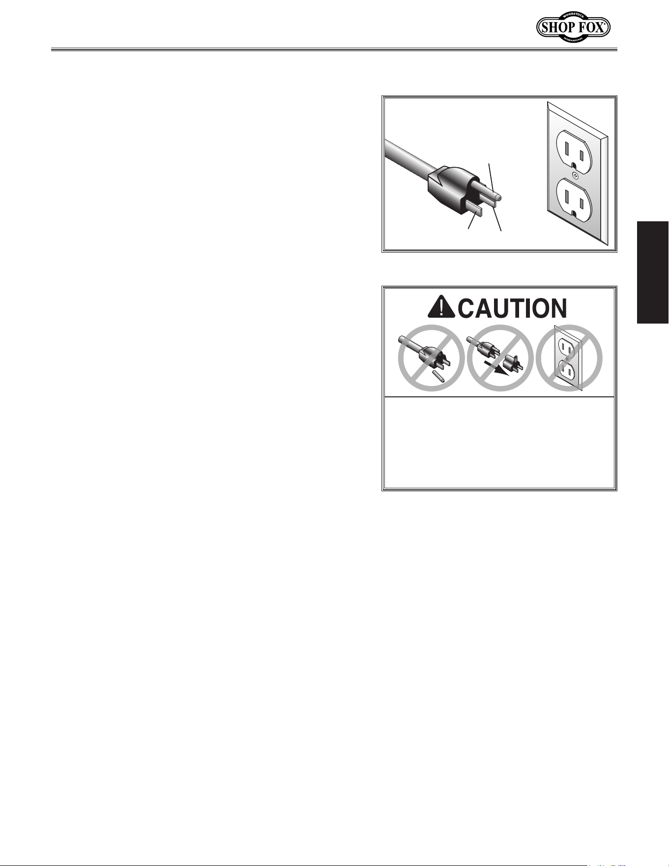
If you ever notice that a cord or
plug is damaged or worn, disconnect it from power, and
immediately replace it with a new one.
Grounding Prong
Neutral Hot
5-15 PLUG
GROUNDED
5-15 RECEPTACLE
110V
Figure.2. NEMA 5-15 plug & receptacle.
DO. NOT. modify. the. provided. plug. or.
use. an. adapter. if. the. plug. will. not.
fit . the. receptacle.. Instead,. have. an.
electrician.install.the.proper.receptacle.
on. a. power. supply. circuit. that. meets.
the.requirements.for.this.machine.
Extension.Cords
We do not recommend using an extension cord with
this machine. Extension cords cause voltage drop, which
may damage electrical components and shorten motor
life. Voltage drop increases with longer extension cords
and smaller gauge sizes (higher gauge numbers indicate
smaller sizes).
Any extension cord used with this machine must contain a
ground wire, match the required
plug and receptacle, and
meet the following requirements:
Minimum.Gauge.Size.at.110V....................... 14.AWG
Maximum.Length.(Shorter.is.Better).................50.ft.
For.110V.Connection.
This machine is equipped with a power cord with an
equipment-grounding
wire and NE M A 5-15 grounding
plug
(see figure). The plug must only be inserted into
a matching
receptacle that is properly installed and
grounded in accordance with local codes and ordinances.
-12-
Model W1843 (For Machines Mfd. Since 3/17)
SETUP
SET UP
Description. Qty
• Safety Glasses ..............................................1
• Cleaner/Degreaser ............................ As Needed
• Disposable Shop Rags ......................... As Needed
• Hex Wrench 4mm ..........................................1
• Hex Wrench 5mm ..........................................1
• Hex Wrench 6mm ..........................................1
• Dead-Blow Hammer .......................................1
• Mounting Hardware (Page 16) ............... As Needed
Items.Needed.for.Setup
Unpacking
This machine has been carefully packaged for safe
transportation. If you notice the machine has been
damaged during shipping, please contact your authorized
Shop Fox dealer immediately.
The following items are needed, but not included, to set
up your machine.
USE. helpers. or. p ower.
lifting. equipment. to. lift.
this.machine..Otherwise,.
serious. personal. injury.
may.occur..
Wear safety glasses during
entire setup process!
This machine presents
serious injury hazards
to untrained users. Read
through this entire manual
to become familiar with
the controls and opera-
tions before starting the
machine!
-13-
Model W1843 (For Machines Mfd. Since 3/17)
SETUP
Hex
Wrench
16mm
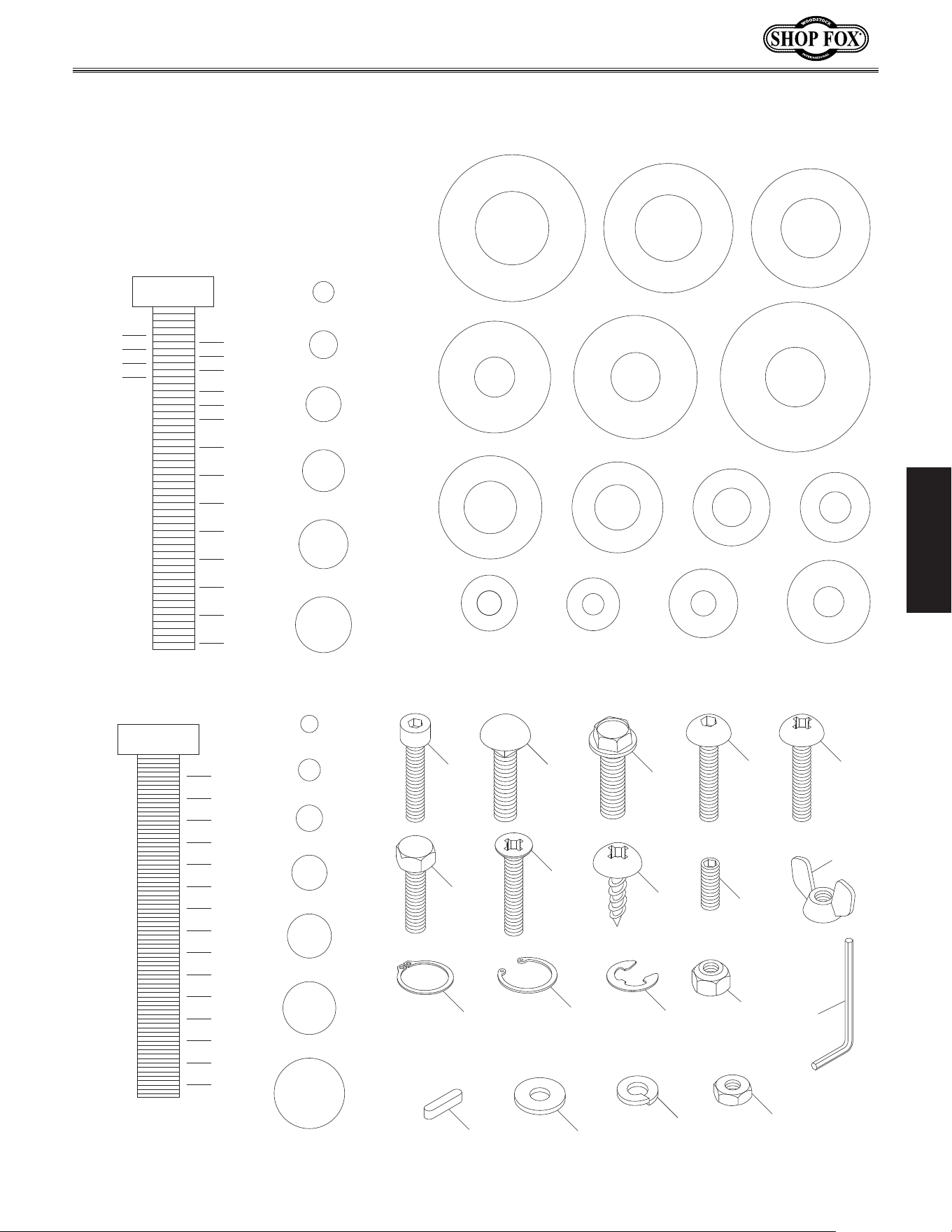
MEASURE BOLT DIAMETER BY PLACING INSIDE CIRCLE
7
⁄16"
3
⁄8"
1
⁄4"
5
⁄16"
#10
1
⁄2"
WASHERS ARE MEASURED BY THE INSIDE DIAMETER
USE THIS CHART TO IDENTIFY
HARDWARE DURING THE
INVENTORY/ASSEMBLY
PROCESS.
Flat Washer
Lock
Washer
Hex
Nut
Wing
Nut
Set
Screw
Cap
Screw
Carriage
Bolt
Hex
Bolt
Button
Head
Screw
Flange
Bolt
LINES ARE
1
⁄16" INCH APART
1
⁄4"
3
⁄8"
1
⁄2"
5
⁄8"
5
⁄16"
7
⁄16"
9
⁄16"
3
⁄4"
7
⁄8"
3
2
1
⁄4"
2
1
⁄2"
2
3
⁄4"
2
1
3
⁄4"
1
1
⁄2"
1
1
⁄4"
1
LINES ARE 1MM APART
5mm
10mm
20mm
15mm
25mm
40mm
30mm
35mm
45mm
50mm
60mm
55mm
70mm
65mm
75mm
W
A
S
H
E
R
D
I
A
M
E
T
E
R
5
⁄8"
W
A
S
H
E
R
D
I
A
M
E
T
E
R
9
⁄16"
1
⁄2"
W
A
S
H
E
R
D
I
A
M
E
T
E
R
W
A
S
H
E
R
D
I
A
M
E
T
E
R
12mm
W
A
S
H
E
R
D
I
A
M
E
T
E
R
10mm
7
⁄16"
W
A
S
H
E
R
D
I
A
M
E
T
E
R
W
A
S
H
E
R
D
I
A
M
E
T
E
R
8mm
3
⁄8"
W
A
S
H
E
R
D
I
A
M
E
T
E
R
5
⁄16"
W
A
S
H
E
R
D
I
A
M
E
T
E
R
1
⁄4"
W
A
S
H
E
R
D
I
A
M
E
T
E
R
#10
W
A
S
H
E
R
D
I
A
M
E
T
E
R
W
A
S
H
E
R
D
I
A
M
E
T
E
R
4mm
W
A
S
H
E
R
D
I
A
M
E
T
E
R
6mm
W
A
S
H
E
R
D
I
A
M
E
T
E
R
5mm
4mm
6mm
5mm
8mm
10mm
12mm
Tap
Screw
Phillips
Head
Screw
Flat
Head
Screw
E-Clip
External
Retaining
Ring
Internal
Retaining
Ring
Key
Lock
Nut
Hardware.Recognition.Chart
-14-
Model W1843 (For Machines Mfd. Since 3/17)
SETUP
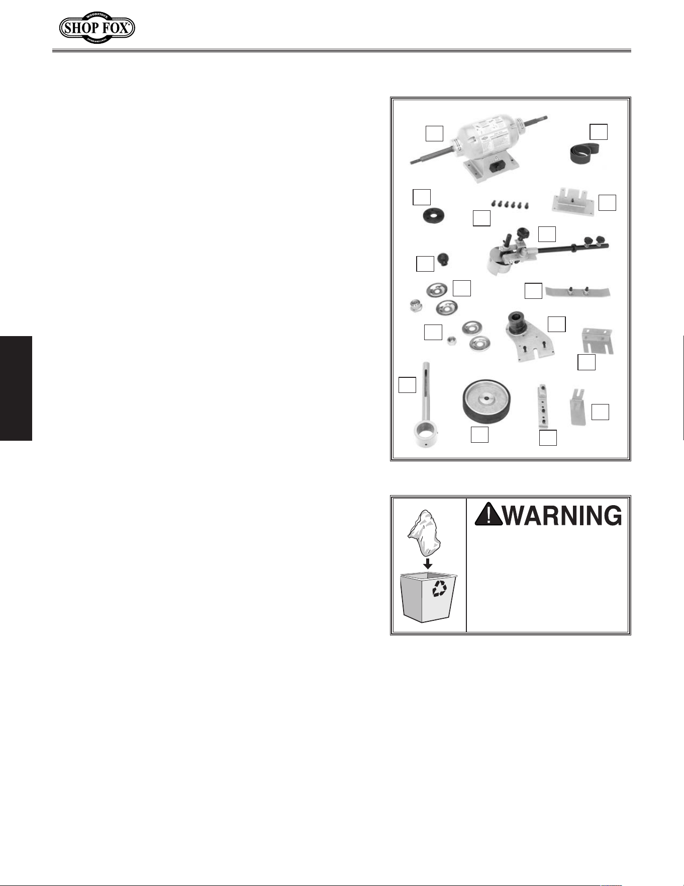
Inventory.(Figure.3). Qty
A. Motor Assembly ............................................1
B. Sanding Belt 2" x 72" 100-Grit ...........................1
C. Mounting Adapter ..........................................1
D. Cap Screws
1
⁄4"-20 x
1
⁄2" .................................6
E. Pivot Arm Mounting Bracket .............................1
F. Quick-Release Lever Knob ................................1
G. Sanding Arm Assembly ....................................1
H. Auxiliary Arbor Flanges & Hex Nut
5
⁄8"-18LH ..........1
I. Platen Bracket .............................................1
J. Drive Wheel Arbor Flanges & Hex Nut
3
⁄4"-16 .........1
K. Pivot Arm Bracket .........................................1
L. Platen Bracket .............................................1
M. Pivot Arm ...................................................1
N. Drive Wheel 10" ............................................1
O. Tool Rest Support Assembly ..............................1
P. Tool Rest ....................................................1
Inventory
Figure.3. Machine inventory.
A
B
H
O
P
I
J
K
L
M
N
C
D
E
F
G
The following is a list of items shipped with your machine.
Before beginning setup, lay these items out and inventory
them.
Note:
If you cannot find an item on this list, carefully
check around/inside the machine and packaging materials.
Often, these items get lost in packaging materials while
unpacking or they are pre-installed at the factory.
SUFFOCATION HAZARD!
Immediately discard all
plastic bags and packing
materials to eliminate
choking/suffocation
hazards for children and
animals.
-15-
Model W1843 (For Machines Mfd. Since 3/17)
SETUP
12
1
/
4
"
29"
Figure.4. Machine clearances.
Cleani ng.MachineMachine.Placement
Workbench.Load
Refer to the Machin e.Specifications for the
weight and footprint specifications of your
machine. Some workbenches may require
additional reinforcement to support the weight
of the machine and workpiece materials.
Consider anticipated workpiece sizes and
additional space needed for auxiliary stands,
work tables, or other machinery when
establishing a location for this machine in the
shop. Below is the minimum amount of space
needed for the machine.
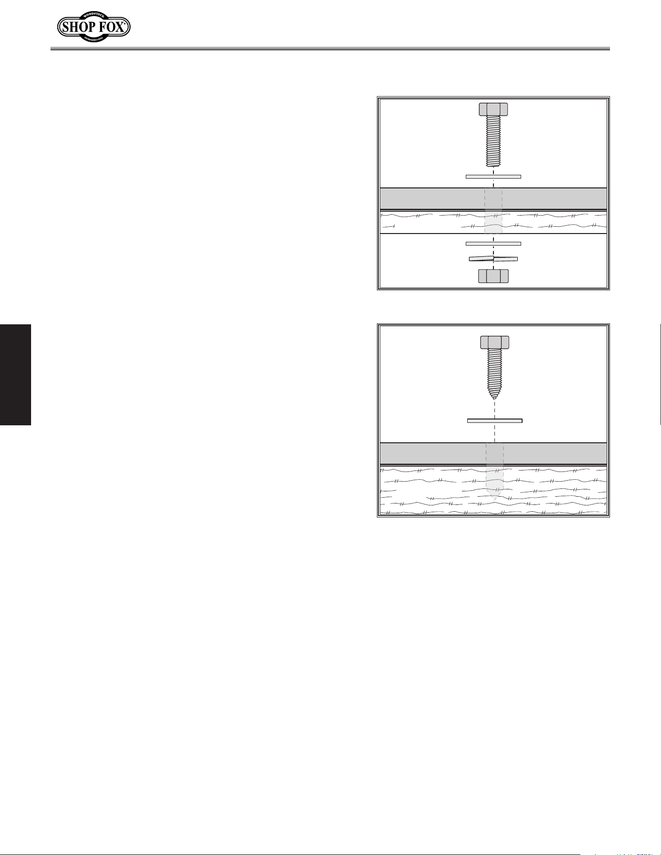
Placement.Location
INJURY.HAZARD!.Untrained.
users.can.injure.themselves.
with.this.machine..Restrict.
access. to. machine. when.
you.are.away,. especially.if.
it. is. installed. where. chil-
dren.are.present.
The unpainted surfaces of your machine are
coated with a heavy-duty rust preventative that
prevents corrosion during shipment and storage.
This rust preventative works extremely well, but
it will take a little time to clean.
Be patient and do a thorough job cleaning your
machine. The time you spend doing this now will
give you a better appreciation for the proper
care of your machine's unpainted surfaces.
There are many ways to remove this rust
preventative, but the following steps work well
in a wide variety of situations. Always follow the
manufacturer’s instructions with any cleaning
product you use and make sure you work in a
well-ventilated area to minimize exposure to
toxic fumes.
Before.cleaning,.gather.the.following:
• Disposable rags
• Cleaner/degreaser (WD•40 works well)
• Safety glasses & disposable gloves
• Plastic paint scraper (optional)
Basic.steps.for.removing.rust.preventative:
1.
Put on safety glasses.
2.
Coat the rust preventative with a liberal
amount of cleaner/degreaser, then let it
soak for 5–10 minutes.
3.
Wipe off the surfaces. If your cleaner/
degreaser is effective, the rust
preventative will wipe off easily. If you
have a plastic paint scraper, scrape off as
much as you can first, then wipe off the
rest with the rag.
4.
Repeat Steps.2–3 as necessary until clean,
then coat all unpainted surfaces with a
quality metal protectant to prevent rust.
Avoid. chlorine-based. solvents,. such. as.
acetone. or. brake. parts. cleaner,. that. may.
damage.painted.surfaces..
-16-
Model W1843 (For Machines Mfd. Since 3/17)
SETUP
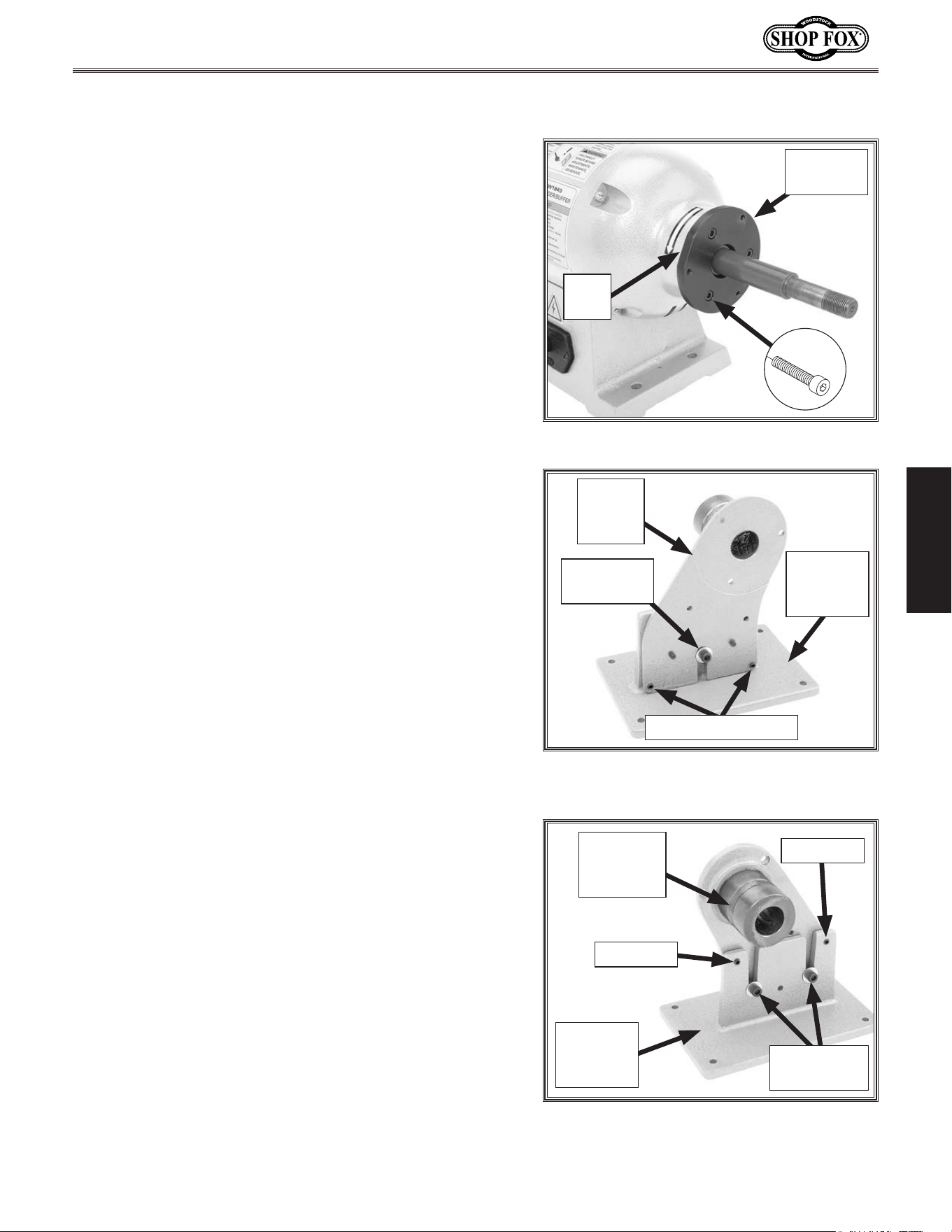
Bench.Mounting
Number.of.Mounting.Holes................................... 8
Diameter.of.Mounting.Hardware.Needed...............
1
⁄2"
Machine Base
Workbench
Bolt
Flat Washer
Flat Washer
Lock Washer
Hex Nut
Figure.5. Typical "Through Mount" setup.
Machine Base
Workbench
Lag Screw
Flat Washer
Figure.6. Typical "Direct Mount" setup.
Another option is a “Direct Mount” (see example) where
the machine is secured directly to the workbench with lag
screws and washers.
The base of this machine has mounting holes that allow it
to be fastened to a workbench or other mounting surface
to prevent it from moving during operation and causing
accidental injury or damage.
The strongest mounting option is a “Through Mount” (see
example) where holes are drilled all the way through the
workbench—and hex bolts, washers, and hex nuts are
used to secure the machine in place.
-17-
Model W1843 (For Machines Mfd. Since 3/17)
SETUP
Assembly
Before beginning the assembly process, refer to Items.
Needed.for.Setup
and gather everything you need.
Ensure all parts have been properly cleaned of the
heavy-duty rust-preventative applied at the factory, if
applicable. Be sure to complete all steps in the assembly
procedure prior to performing the Test.Run.
To.assemble.machine,.do.these.steps:
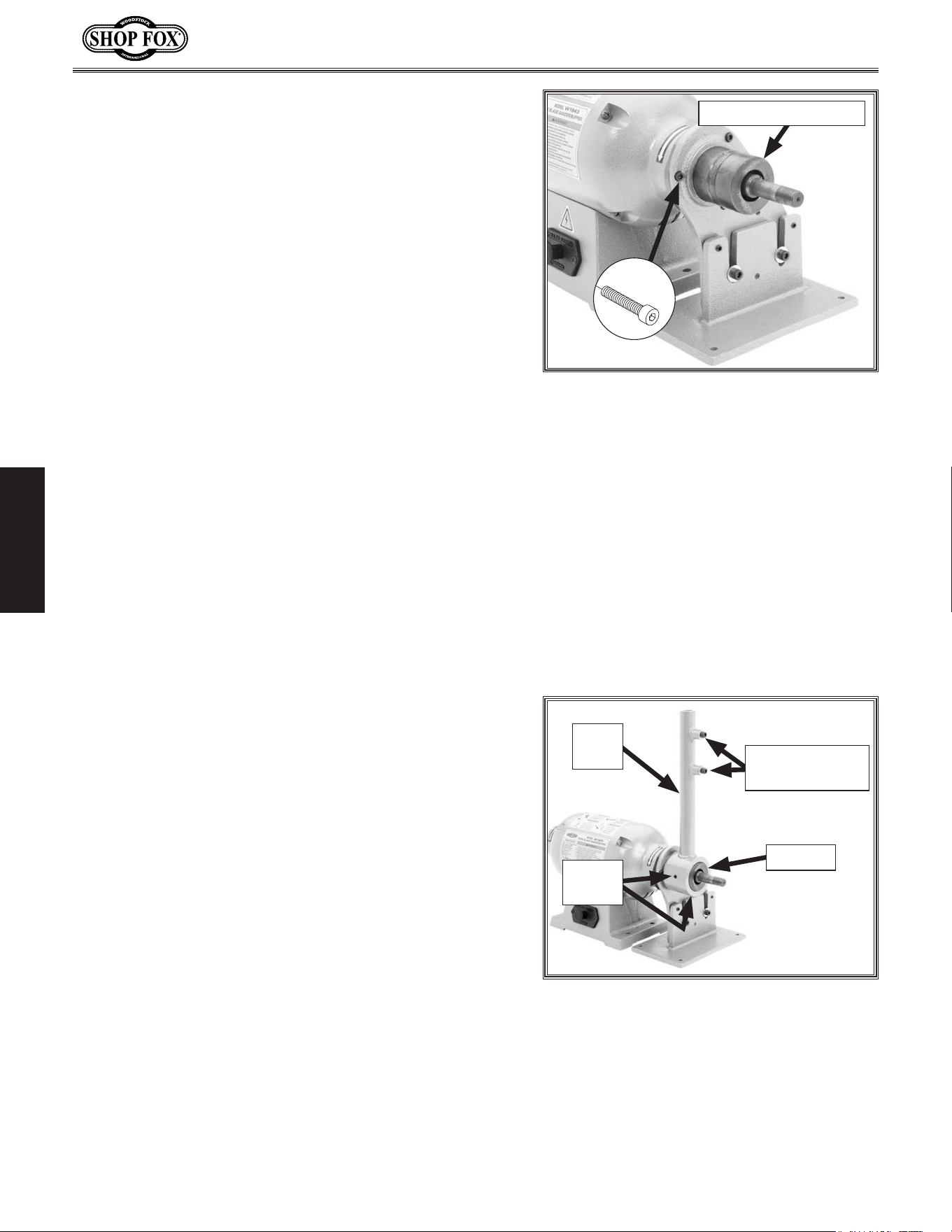
1... Slide the mounting adapter onto the right-hand arbor
of the motor assembly with the countersunk holes
facing out, then rotate it so that the flat edge is at
the 10 o'clock position, as shown in Figure 7.
2. Secure the adapter to the motor assembly with (3)
1
⁄4"-20 x
1
⁄2" cap screws (see Figure 7).
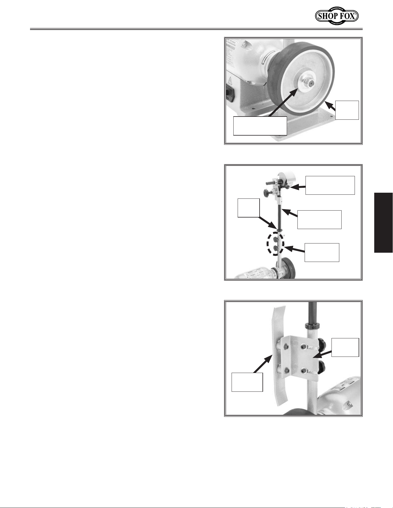
3. Back out the (3) cap screws and (4) set screws
in the pivot arm mounting bracket and the pivot
arm bracket, then slide the pivot arm bracket
onto the pivot arm mounting bracket, as shown in
Figures 8–9.
Note: The pivot arm bracket bushing is shipped with
a lubricating grease coating on its outer surface.
This lubricant will keep the motion of the pivot arm
smooth during operation and reduce the wear on the
metal-to-metal surfaces.
4. For now, finger-tighten the three cap screws enough
to hold the two brackets together. You will fully
tighten these fasteners in a later step.
Note: Make sure the four set screws DO NOT make
contact with the opposite bracket.
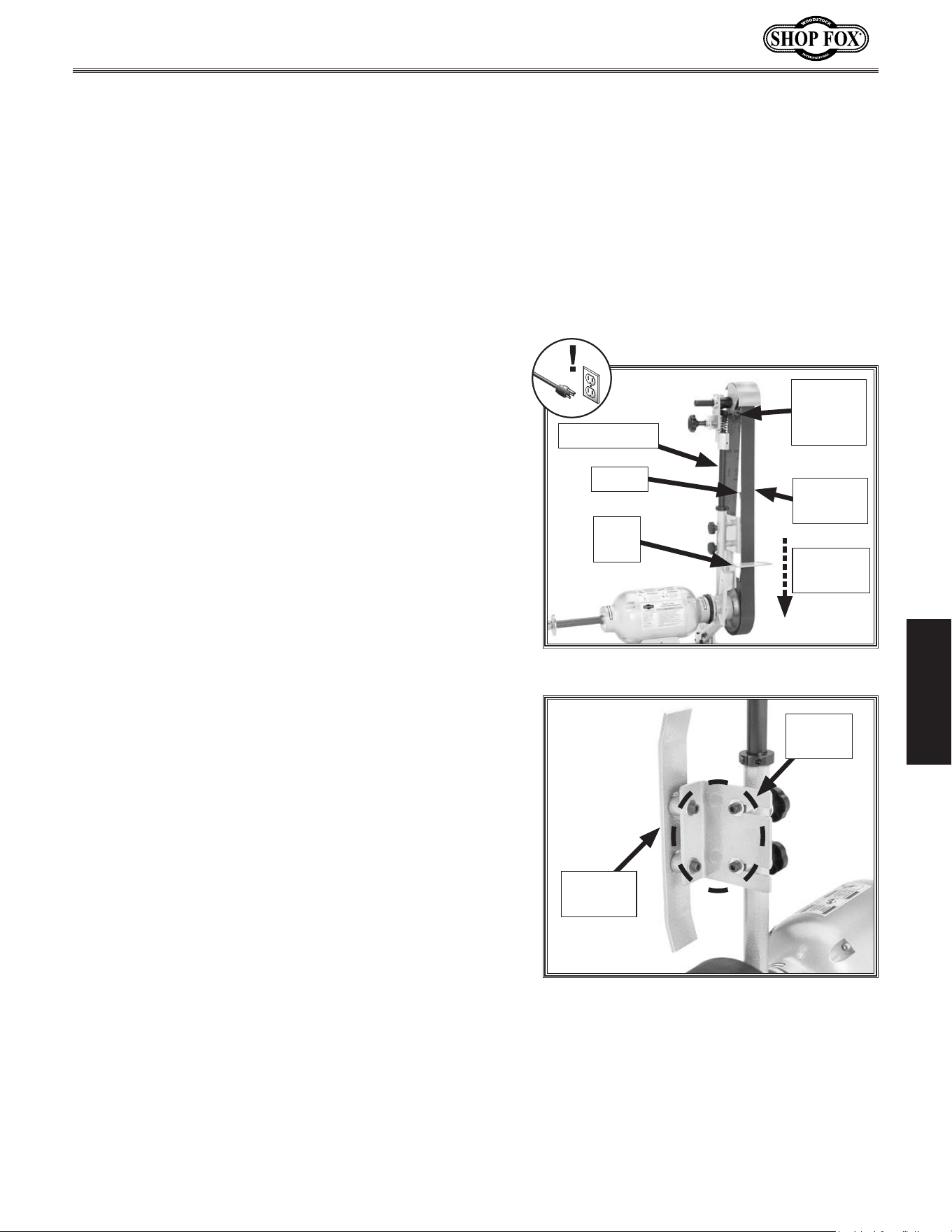
Figure 7. Mounting adapter installed.
x 3
Mounting
Adapter
Flat
Edge
Figure 8. Left side of pivot arm bracket
assembly.
Pivot Arm
Mounting
Bracket
Pivot
Arm
Bracket
Cap Screw
(1 of 3)
Set Screws (2 of 4)
Figure 9. Right side of pivot arm bracket
assembly.
Pivot Arm
Mounting
Bracket
Pivot Arm
Bracket
Bushing
Set Screw
Cap Screws
(2 of 3)
Set Screw
-18-
Model W1843 (For Machines Mfd. Since 3/17)
SETUP
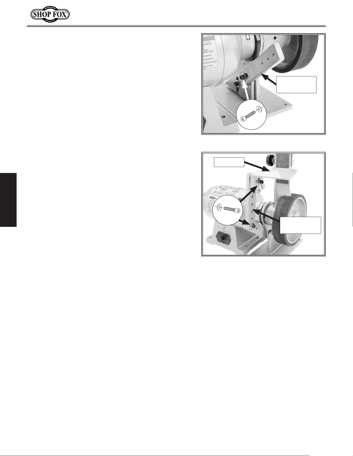
5. Slide the assembled arm brackets onto the right-
hand arbor with the arm bracket bushing facing
out, as shown in Figure 10, then secure it with the
remaining (3)
1
⁄4"-20 x
1
⁄2" cap screws.
6. Move the machine to the selected mounting surface,
and use the eight holes in the base of the motor
assembly and the pivot arm bracket assembly as a
template for drilling the mounting holes.
7. Loosen the three cap screws of the pivot arm
bracket assembly (see Figures 8–9 on Page.17),
then use the mounting hardware you have chosen to
firmly secure the motor assembly and the bracket
assembly in place.
Note: Before fully tightening the mounting
hardware, make sure that the three cap screws and
four set screws of the arm bracket assembly are
loose. This will allow the mounting bracket to lay
flat on the mounting surface.
8. Tighten the four set screws in the pivot arm bracket
assembly (see Figures 8–9.on Page.17) just until you
feel resistance. This will keep the two parts of the
assembly stable during operation.
9. Fully tighten the three cap screws on the pivot arm
bracket assembly.
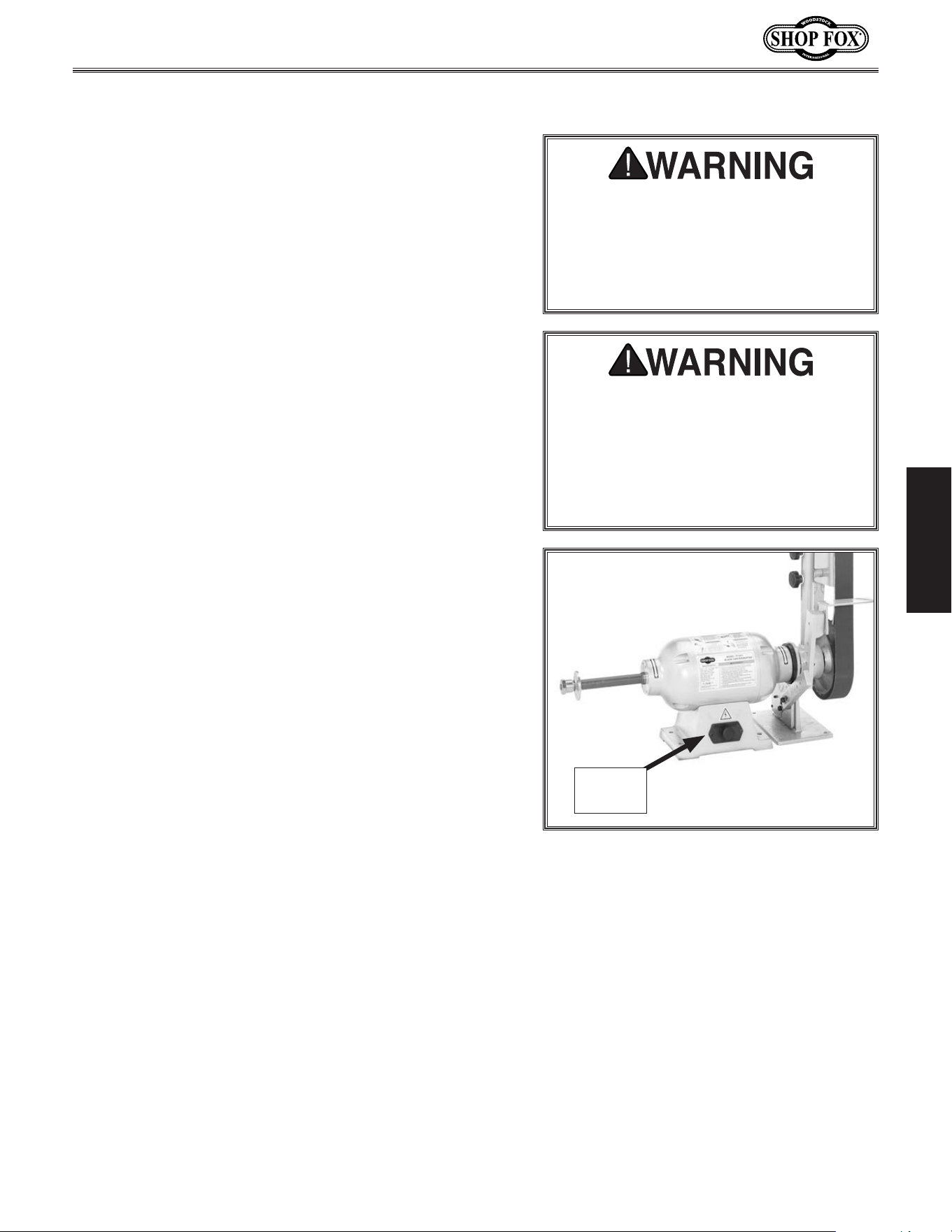
10. Back out the two set screws in the round end of the
pivot arm, slide the arm onto the bracket bushing so
that the platen bracket cap screws are facing to the
right, as shown in Figure 11, then tighten the set
screws to hold the pivot arm in place.
Note: The pivot arm and bushing are designed so
that the set screws tighten into the grooved surface
of the bushing. This keeps the pivot arm from
sliding off the bushing when using the tilt feature.
Figure 10. Pivot arm bracket assembly
installed onto the motor assembly.
x 3
Arm Bracket Bushing
Figure 11. Pivot arm installed.
Bushing
Platen Bracket
Cap Screws
Pivot
Arm
Set
Screws
-19-
Model W1843 (For Machines Mfd. Since 3/17)
SETUP
11. Slide the drive wheel onto the right-hand arbor with
a drive wheel flange (
3
⁄4" center bore) on each side,
then secure it in place with the remaining
3
⁄4"-16
arbor hex nut (see Figure 12).
Note: It may be necessary to use a dead-blow
hammer to seat the drive wheel onto the arbor.
Take great care not to damage the drive wheel or
the threads of the arbor.
Figure 12. Drive wheel installed.
Drive
Wheel
Outer Flange &
Arbor Hex Nut
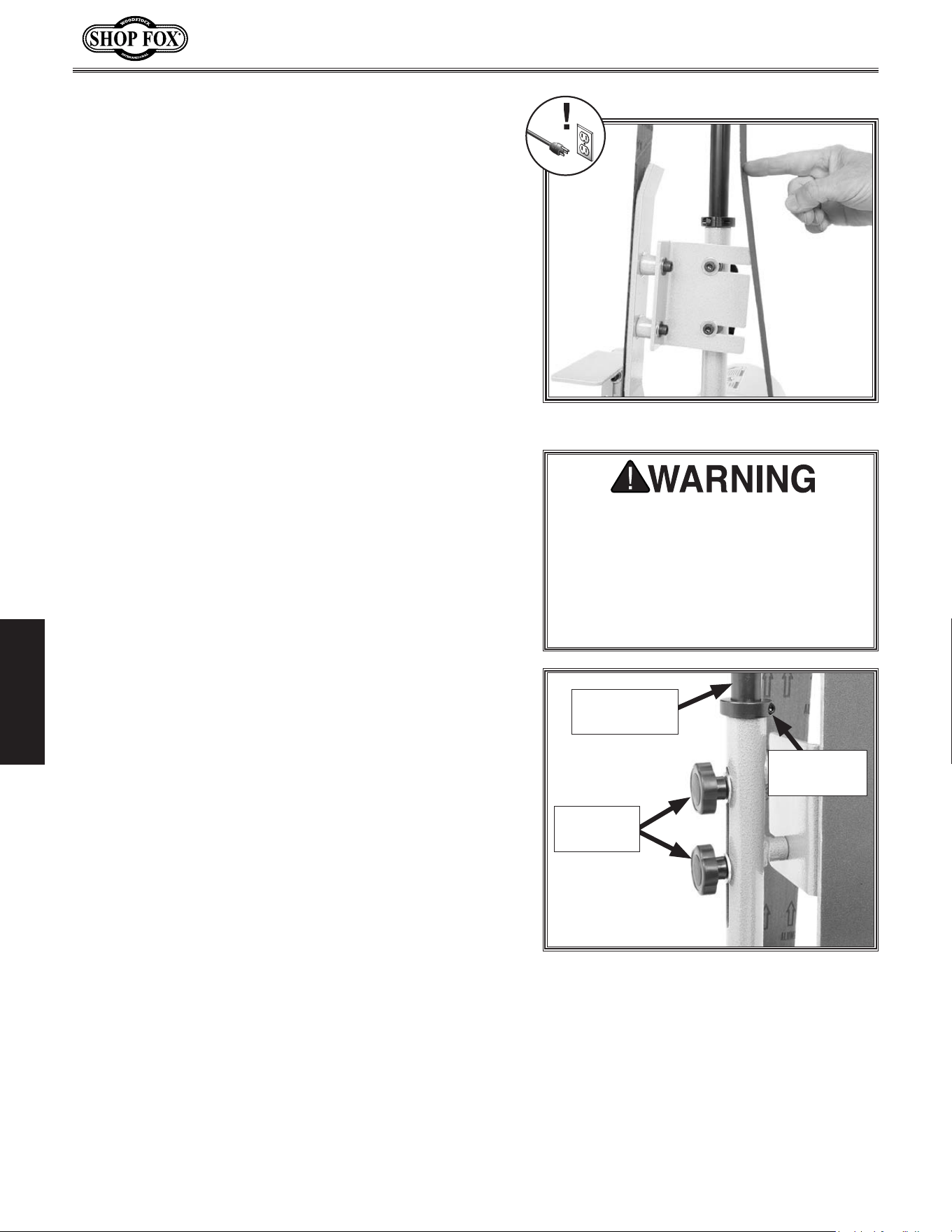
12. Remove the two threaded knobs and flat washers
from the sanding arm assembly, insert the shaft into
the pivot arm tube until the lock collar rests on top
of the tube, as shown in Figure 13, then re-install
the knobs and flat washers to hold it in place.
13. Install the quick-release lever knob, as shown in
Figure 13.
Figure 13. Sanding arm assembly installed.
Lock
Collar
Quick-Release
Lever Knob
Sanding Arm
Assembly
Threaded
Knobs
14. Install the platen bracket onto the pivot arm with
the pre-installed hardware, as shown in Figure 14.
15. Install the sanding platen onto the platen bracket
with the pre-installed hardware, as shown in
Figure 14.
Figure 14. Sanding platen and bracket
installed on pivot arm.
Platen
Bracket
Sanding
Platen
-20-
Model W1843 (For Machines Mfd. Since 3/17)
SETUP
16. Remove the (3) cap screws and flat washers that
hold the two pieces of the tool rest support assembly
together.
17. Mount the first tool rest support to the back of the
arm bracket with the
5
⁄16"-18 x
3
⁄4" cap screw (the
shortest of the three) and flat washer removed in
Step 16, as shown in Figure 15.
18. Position the second tool rest support so that its flat
side faces the first support, then secure it with (1)
5
⁄16"-18 x 1
1
⁄4" cap screw and flat washer removed in
Step 16, as shown in Figure 16.
Note: There are several holes provided for attaching
the tool rest assembly so that you can choose the
best position for your operation.
19. Secure the tool rest to the support assembly with
the remaining
5
⁄16"-18 x 1
1
⁄4" cap screw and flat
washer, as shown in Figure 16.
Note: When the sanding belt is installed and
properly tensioned, there should be no more than
1
⁄16" between the tool rest and the belt to ensure
the workpiece will not become trapped between the
rest and belt during operation.
Figure 16. Tool rest installed.
X 2
Second Tool
Rest Support
Tool Rest
Figure 15. First tool rest bracket installed.
First Tool
Rest Support
-21-
Model W1843 (For Machines Mfd. Since 3/17)
SETUP
Test. Run
To test run the machine, do these steps:
1. Make sure all tools and objects used during setup are
cleared away from the machine, and that a sanding
belt or auxiliary attachment are NOT installed on the
machine.
2. Make sure the ON/OFF button (see Figure 17) is
pushed in, then connect the machine to power.
3. Pull the ON/OFF button out to turn the machine ON.
4. Listen to and watch for abnormal noises or actions.
The machine should run smoothly with little or no
vibration or rubbing noises.
— Strange or unusual noises should be investigated
and corrected before operating the machine
further. Always disconnect the machine from
power when investigating or correcting potential
problems.
5. Push the ON/OFF button in to turn the machine
OFF.
Figure 17. Location of ON/OFF button.
ON/OFF
Button
Once assembly is complete, test run the machine to
ensure it is properly connected to power and safety
components are functioning properly.
If you find an unusual problem during the test run,
immediately stop the machine, disconnect it from power,
and fix the problem BEFORE operating the machine again.
The
Troubleshooting table in the SERVI CE
section of this
manual can help.
Serious. injury. or. death. can. result.
from. using. this. machine. BEFORE.
understanding. its. controls. and. related.
safety.information..DO.NOT.operate,.or.
allow.others.to.operate,.machine.until.
the.information.is.understood..
DO. NOT. start. machine. until. all.
preceding.setup.instructions.have.been.
performed..Operating.an.improperly.set.
up. machine. may. result. in. malfunction.
or. unexpected. results. that. can. lead.
to. serious. injury,. death,. or. machine/
property.damage.
-22-
Model W1843 (For Machines Mfd. Since 3/17)
OPERATIONS
OPERATIONS
To. reduce. your. risk. of. serious. injury.
or. damage. to. the. machine,. read. this.
entire.manual.BEFORE.using.machine.
To. reduce. the. risk. of. eye. injury. and.
long-term. respiratory. damage,. always.
wear. s afety. glasses. and. a. respirator.
while.operating.this.machine.
If you are an inexperienced operator, we
strongly recommend that you read books
or trade articles, or seek training from
an experienced operator of this type of
machinery before performing unfamiliar
operations. Above.all,.safety.must.come.
firs t!
General
To complete a typical sanding operation, the operator
does the following:
1. Examines the workpiece to make sure it is suitable
for sanding.
2. Installs the correct sanding belt for the operation
(composition and grit).
3. Turns the drive wheel by hand to make sure the
sanding belt is tracking correctly and is properly
tensioned.
4. Verifies that the platen is centered on the sanding
belt.
5. Adjusts the tool rest to the correct position for the
operation and makes sure that it is no more than
1
⁄16" away from the sanding belt.
6. Connects the machine to power and pulls the ON/
OFF button out to turn it ON.
7. Verifies that the sanding belt is tracking properly and
rotating without interference.
8. Places the workpiece onto the tool rest and slowly
moves it into the sanding belt with the direction of
the belt.
9. Removes the workpiece and pushes the ON/OFF
button in to turn the machine OFF.
The purpose of this overview is to provide the novice
machine operator with a basic understanding of how
the machine is used during operation, so the
machine
controls
/components discussed later in this manual are
easier to understand.
Due to the generic nature of this overview, it is
not
intended to be an instructional guide. To learn more
about specific operations,
read this entire manual and
seek
additional training from experienced machine
operators
, and do additional research outside of this
manual by reading "how-to" books, trade magazines, or
websites.
Loose hair, cloth-
ing, or jewelry
could get caught
in machinery and
cause serious
personal injury.
Keep these items
away from moving
parts at all times
to reduce this risk.
-23-
Model W1843 (For Machines Mfd. Since 3/17)
OPERATIONS
Sanding.Belt
Sanding Belt Width .......................................... 2"
Sanding Belt Length ........................................72"
To ensure a safe operation and good sanding results, the
sanding belt must be properly installed, tensioned, and
tracked.
Tool.Needed. Qty
Hex Wrench 6mm ...............................................1
Installing.Sanding.Belt
1. DISCONNECT MACHINE FROM POWER!
2. With the direction arrows printed on the inside front
of the belt facing down, pull down on the quick
release lever and wrap the belt around the idler and
drive wheels so that it is centered on both, as shown
in Figure 18, then release the lever.
Note: To prevent the belt seam from catching on
the workpiece, install the belt so that the direction
arrows printed on the inside face of the belt follow
the belt rotation, as shown in Figure 18.
Figure 18. Sanding belt installed.
Quick-
Release
Lever
Tool
Rest
Sanding
Belt
Platen
Belt
Direction
Vertical Rod
Figure 19. Sanding platen adjustment
(belt removed for clarity).
Cap
Screws
Sanding
Platen
3. Adjust the platen by loosening both cap screws
securing platen to vertical rod (see Figure 19).
Center platen behind the belt, and re-tighten cap
screws.
Note: The platen provides a solid back rest and
helps reduce friction as belt passes the tool rest.
Platen should be lightly touching backside of belt,
but not bowing belt outward.
4. If needed for your operation, adjust the tool rest
position as required. Make sure that it is no more
than
1
⁄16" away from the sanding belt to prevent the
workpiece being trapped between the tool rest and
belt.
-24-
Model W1843 (For Machines Mfd. Since 3/17)
OPERATIONS
To correctly tension the sanding belt, do these steps:
1. DISCONNECT MACHINE FROM POWER!
2. Make sure the sanding belt is correctly installed and
centered on the idler and drive wheels.
If sanding belt comes loose from
machine during operation, it could
cause serious personal injury from
entanglement or abrasion. ALWAYS
make sure sanding belt is properly
installed, tensioned, and tracked
before connecting machine to power.
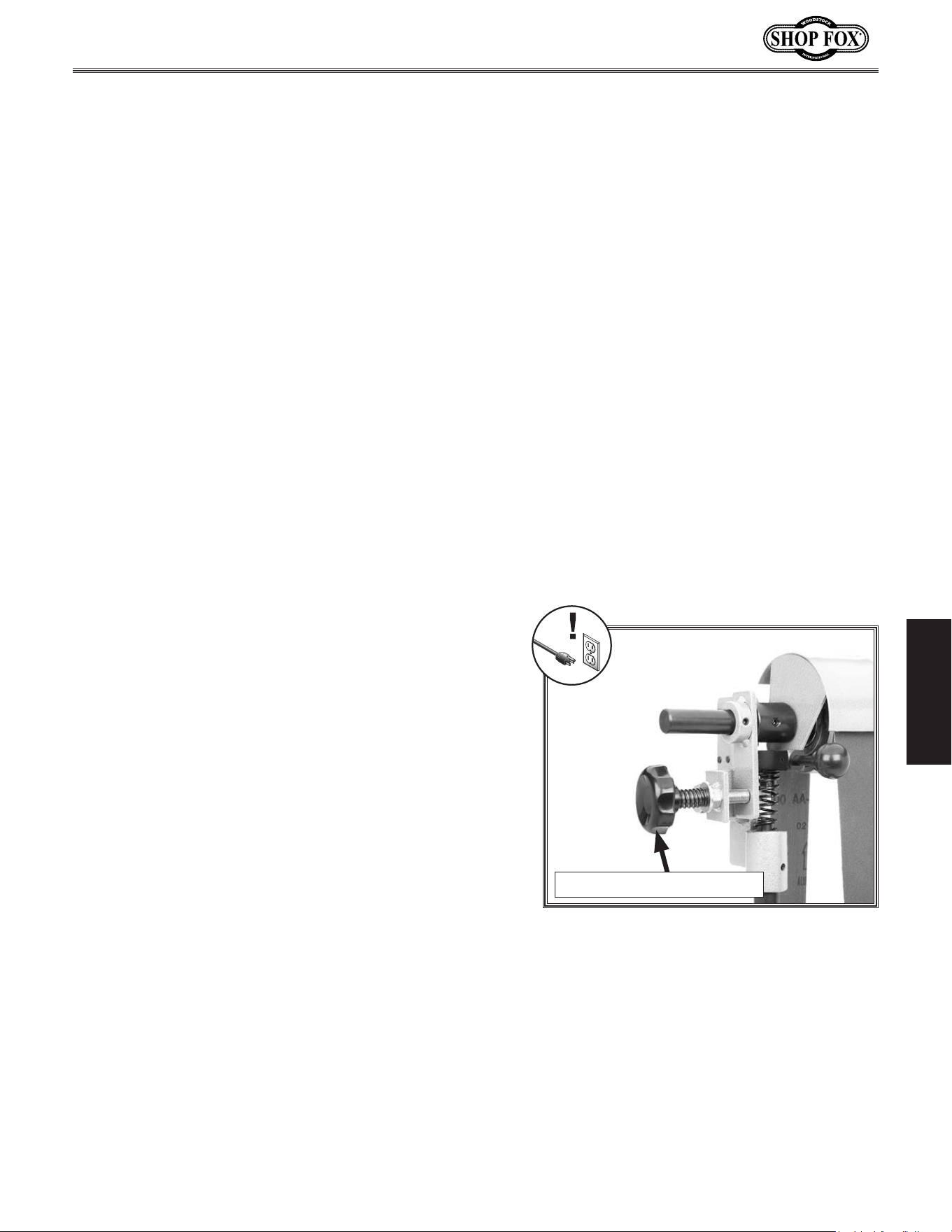
3. Hold onto the sanding arm assembly to keep it from
moving, then loosen the threaded knobs and the lock
collar cap screw shown in Figure 21.
4. Adjust the height of the sanding arm assembly
so there is the correct amount of tension on the
sanding belt, then re-tighten the threaded knobs to
hold the assembly in place.
5. Adjust the lock collar so that it is firmly seated on
the pivot arm top, then re-tighten its cap screw.
Note: The lock collar ensures the stability and
position of the sanding arm beyond the holding
power of the threaded knobs.
6. Re-check the sanding belt tension. If necessary,
repeat this procedure until the correct belt tension
is achieved.
Figure 21. Sanding belt tension controls.
Lock Collar
Cap Screw
Threaded
Knobs
Sanding Arm
Assembly
Figure 20. Checking sanding belt tension.
The sanding belt is properly tensioned when there is
approximately
1
⁄2" deflection with slight pressure applied
to the back loop of the belt, as shown in Figure 20.
The sanding belt tension is adjusted by raising or lowering
the sanding arm assembly.
Tool.Needed. Qty
Hex Wrench
3
⁄16" ................................................1
Tensioning.Sanding.Belt
-25-
Model W1843 (For Machines Mfd. Since 3/17)
OPERATIONS
Adjusting.Sanding.Belt.Tracking
To ensure safe operation, the sanding belt must stay
centered on the idler and drive wheels while the machine
is ON. This is a trial-and-error process that requires some
patience.
To adjust the sanding belt tracking, do these steps:
1. DISCONNECT MACHINE FROM POWER!
2. Make sure the sanding belt is correctly installed and
tensioned (refer to the Sanding Belt subsection on
Page 23 for detailed instructions).
3. Rotate the drive wheel several times by hand and
watch the sanding belt as it tracks on the idler and
drive wheels.
— If the sanding belt is centered on the idler and
drive wheels, and does not move to one side
or the other after several rotations, no further
adjustments are necessary.
— If the sanding belt moves to one side or the other
while rotating, continue with this procedure.
4. Make a small adjustment to the tracking adjustment
knob, then rotate the drive wheel several times
while observing the sanding belt (see Figure 22).
— If the sanding belt moves to the right, rotate the
adjustment knob clockwise.
— If the sanding belt moves to the left, rotate the
adjustment knob counterclockwise.
5. Repeat Step 4 until the sanding belt stays centered
on the idler and drive wheels after several rotations.
6. To verify the sanding belt tracking, turn the machine
ON and watch the belt tracking.
— If the belt does not wander, then it is tracking
correctly.
— If the belt does wander, very slowly adjust the
tracking adjustment knob until the belt stays
centered on the wheels.
Figure 22. Sanding belt tracking
adjustment knob.
Tracking Adjustment Knob
-26-
Model W1843 (For Machines Mfd. Since 3/17)
OPERATIONS
Belt.Sanding
The sanding belt is used to sand wood or metal. We
recommend using aluminum oxide sanding belts for wood
and silicon carbide for metal. Refer to Accessories on
Page 34 for options from Shop Fox.
Always be sure the sanding belt is properly installed,
tensioned, and tracked before connecting the machine to
power (refer to the Sanding Belt subsection on Page 23
for detailed instructions).
Always adjust the tool rest so that it is no more than
1
⁄16" away from the belt. This helps to ensure that the
workpiece does not get trapped between the rest and the
belt.
Make sure the platen is centered on the sanding belt.
Adjust the platen by loosening both cap screws securing
platen to the vertical rod, then re-tighten the cap screws.
Note: The platen provides a solid back rest and helps
reduce friction as the belt passes the tool rest. Platen
should be lightly touching backside of belt, but not
bowing belt outward.
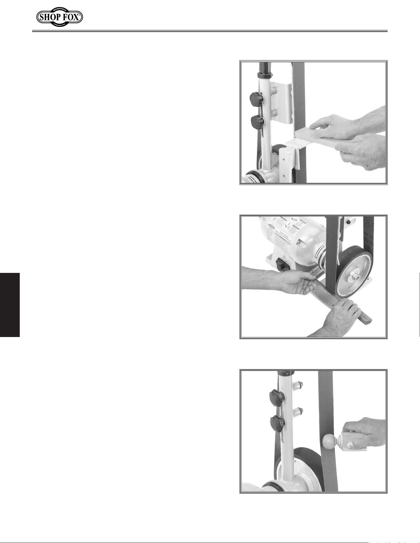
Figure 23 shows a typical wood sanding operation with
the tool rest perpendicular to the belt surface.
The sanding belt is also used for knife grinding and
sharpening. Figure 24 depicts a typical knife edge
grinding operation. Generally, this is done with the tool
rest removed.
Note: There are many different techniques for using the
sanding belt to grind and sharpen knives. Whichever one
you use, make sure that you hold the knife firmly and
ease it into the belt without excessive pressure to ensure
a safe operation.
The belt is also used for contour sanding. When doing this
type of operation, it is best to remove the platen and the
tool rest so the belt can flex to better conform to the
shape of the workpiece (see Figure 25).
Figure 23. Typical wood sanding
operation.
Figure 24. Typical knife grinding
operation.
Figure 25. An example of contour sanding.
-27-
Model W1843 (For Machines Mfd. Since 3/17)
OPERATIONS
The sanding arm assembly tilts to a horizontal position, as
shown in Figure 27. This arrangement is more convenient
for certain types of sanding or grinding operations.
To position the sanding arm assembly horizontally, do
these steps:
1. DISCONNECT MACHINE FROM POWER!
2. While holding the arm assembly, loosen the two
set screws in the round end of the pivot arm
(see Figure 26).
3. Pivot the assembly to the desired angle, then
re-tighten the pivot arm set screws to secure it in
place.
Figure 26. Pivot arm set screw locations.
x 2
4. Adjust the tool rest in the position (see Figure 27)
that is correct for your operation.
Note: If you will be using the contour of the drive
wheel for sanding or grinding, remove the tool
rest assembly so that it will not interfere with the
operation. Otherwise, you will need to mount it
differently so that it will not interfere with the
sanding belt.
5. Check and adjust, if necessary, the sanding belt
tracking (refer to Adjusting Sanding Belt Tracking
on Page 25 for detailed instructions).
Figure 27. Sanding arm assembly in the
horizontal position.
Tool Rest
Tools.Needed. Qty
Hex Wrench 5mm ...............................................1
Hex Wrench 6mm ...............................................1
-28-
Model W1843 (For Machines Mfd. Since 3/17)
OPERATIONS
Buffing.&.Polishing.Setup
To. reduce. the. risk. of. eye. injury. and.
long-term. respiratory. damage,. always.
wear. s afety. glasses. and. a. respirator.
while.operating.this.machine.
If you are an inexperienced operator, we
strongly recommend that you read books
or trade articles, or seek training from
an experienced operator of this type of
machinery before performing unfamiliar
operations. Above.all,.safety.must.come.
firs t!
The Model W1843 is capable of both buffing and sanding
operations. IT IS NOT A GRINDER. The absence of grinding
wheel guards and eye shields prohibits the use of this
machine as a grinder.
Note: Use caution when polishing plated metals; there is
a chance that the thin plated material may be damaged.
A light pressure is all that is needed for quality work.
Tool.Needed. Qty
Adjustable Wrench ..............................................1
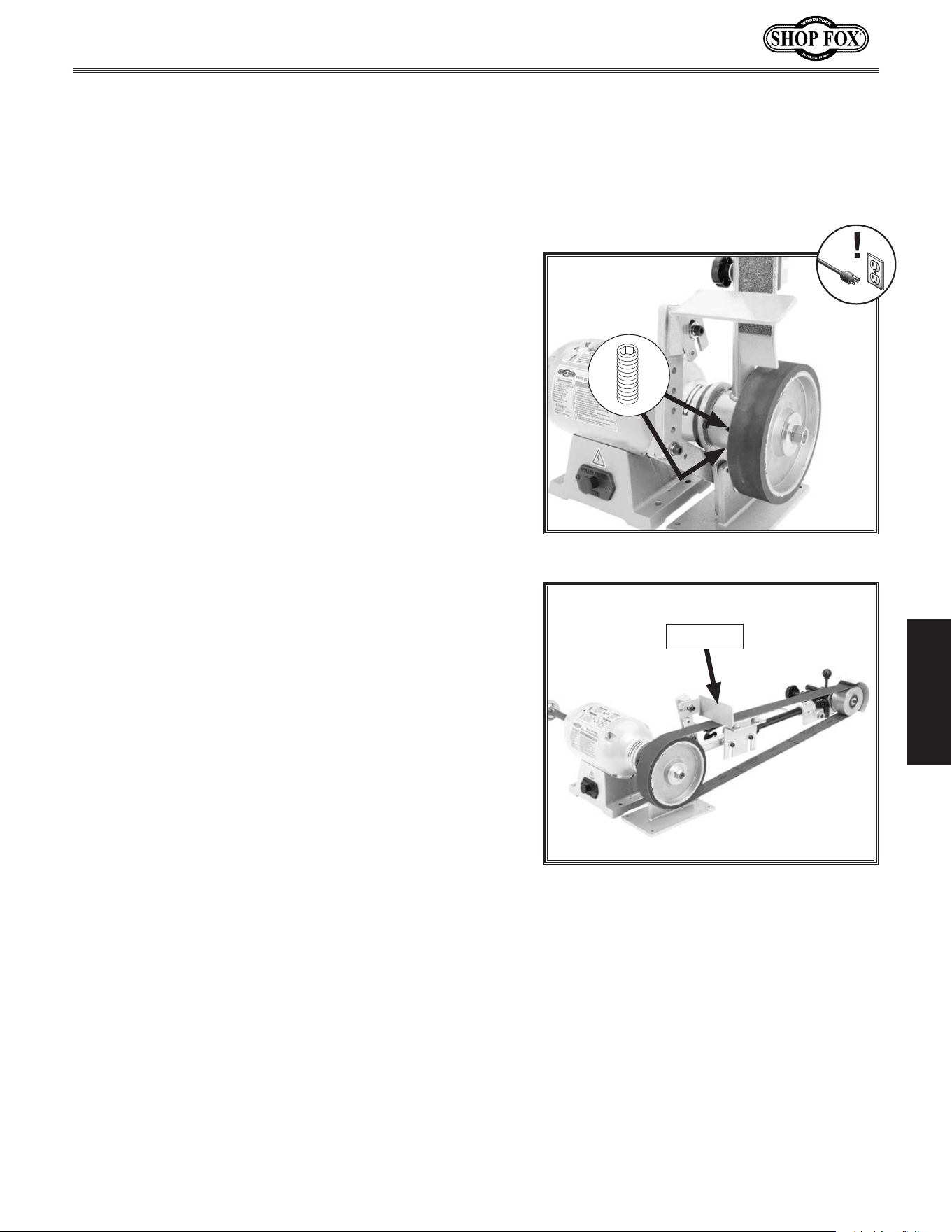
To buff or polish, do these steps:
1. DISCONNECT MACHINE FROM POWER!
2. Remove the arbor nut at the end of the shaft.
3. Insert a buffing wheel (not included) between the
provided wheel flanges. Secure flanges with the
arbor nut removed in the previous step, as shown in
Figure 28.
4. Put on safety glasses and a respirator, then connect
machine to power.
5. Stand to the side of the buffer and turn it ON.
6. Allow the buffer to reach full speed.
7. Select the appropriate stick of polishing compound
for your application, and apply to the rotating face
of the wheel.
8. Once compound is thoroughly applied, firmly grasp
the workpiece with both hands and lightly and
evenly move the workpiece back and forth on the
buffing wheel.
Figure 28. Buffing wheel installed.
CORRECT
Arbor
Nut
Wheel
Flanges
Motor
Arbor
Nut
Flange
(1 of 2)
-29-
Model W1843 (For Machines Mfd. Since 3/17)
OPERATIONS
Below are some quick tips for getting the most out of your
buffer. Remember, there is no substitute for experience.
Learning how to hold the workpiece, how much pressure
to apply, how to move the workpiece against the wheel,
and how much compound to use requires trial and error.
• Thoroughly clean all parts that you plan to buff.
Dirt, oil, rust, paint or other film must be removed
chemically or with water. Dry parts with a rag.
• Apply buffing compounds in small amounts at a time.
Apply paste-type compounds with a wand or directly
to the part. For wax-based polishing stick-type
compounds, press the compound on the wheel for
a couple of seconds while the machine is running.
Avoid using too much compound.
Buffing
• Put your workpiece under the wheel when you
are loading the compound on the buffing wheel.
This way, you will catch any compound that would
normally be wasted on the floor.
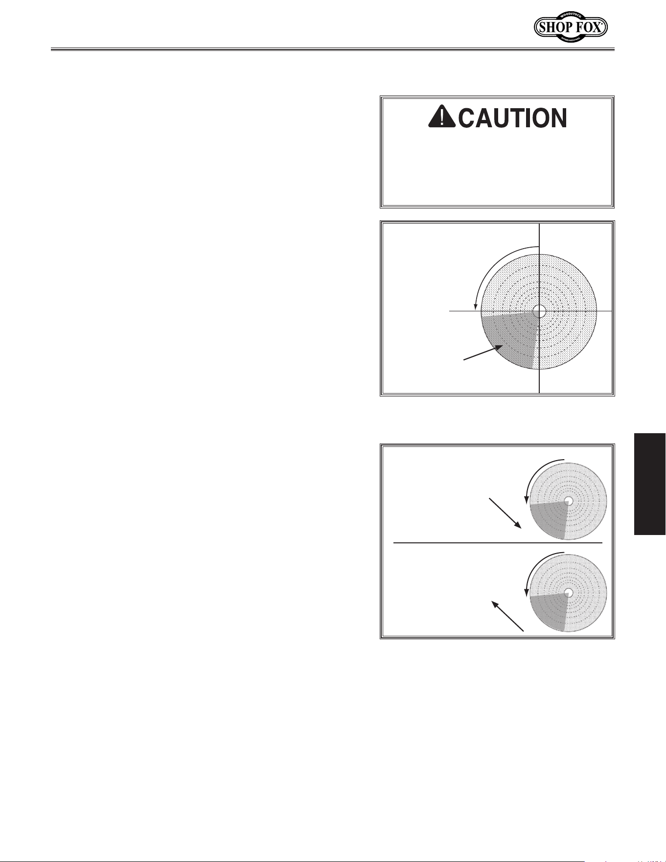
• Only use the area indicated in Figure 29 to do the
actual buffing. Contacting the workpiece on areas
outside the correct area may flip the workpiece out
of your hands.
• Hold the workpiece tightly at all times while buffing.
Placing one hand near the contact point will give you
better control.
• Keep buffing wheels raked out before each use and
when buildup gets heavy during use. Raking means
to clean the buffing wheels with a wheel rake to
remove built-up compounds and metal particles.
ALWAYS use light pressure when raking wheels!
• Do not mix two different compounds on the same
wheel. For best results, use a separate wheel for
each compound.
• Always use an upward stroke with heavy to moderate
pressure for cutting. Use a downward stroke with
light pressure for polishing. See Figure 30.
• Wear safety equipment when buffing. If the buffer
forces the workpiece out of your hand, be prepared
for it to come flying at you! Wear safety glasses or
a face shield and a heavy leather apron. Also, wear
a dust mask to protect your lungs from microscopic
particulate that will be flying off the wheel.
W
h
e
e
l
R
o
t
a
t
i
o
n
Figure.29. Location where workpiece
should contact wheel.
TOP
BOTTOM
FRONT
(Right Front Side View)
Workpiece
Contact Here
Figure.30. Cutting and polishing strokes.
W
h
e
e
l
R
o
t
a
t
i
o
n
W
h
e
e
l
R
o
t
a
t
i
o
n
(Right Front Side View)
Polishing
Stroke
(Downward)
Cutting
Stroke
(Upward)
Never buff with workpiece on top of
the wheel. Workpiece may catch on
wheel and be thrown at operator.
Always buff workpiece near the bot-
tom of the wheel!
-30-
Model W1843 (For Machines Mfd. Since 3/17)
OPERATIONS
Buffing.Compound.
Selection
Most colors of abrasives have similar applications, but
always check with the manufacturer of your particular
compound.
Shop Fox offers the following compounds:
Red Rouge — Made for fine polishing on brass and gold.
Provides an excellent shine when used with the loose
muslin buffing wheel.
Green (Extra Fine) — Great for extra-fine polishing on
most metals to bring out that mirror finish. Works best
with loose muslin and spiral-sewn buffing wheels.
White — Great for ivory, plastic and resins when used
successively with the soft spiral sewn and soft airway
buffing wheels.
Black — Designed to be used with sisal and airway hard
buffing wheels, this compound is perfect for the initial
rough cut on stainless steel and iron.
Tripoli — A true middle-of-the-road abrasive, Tripoli pro-
vides an excellent medium cut for brass, aluminum and
zinc alloy.
Green (Fine) — Slightly more abrasive than the extra
fine green, this green compound is great for a medium to
fine polish with most softer metals.
Plastics
Soft
Metals
Thin
Plating
Gold
Silver
Chrome
&
Nickel
Plate
Copper
Brass
Aluminum
Iron
Steel
Stainless
Compound Type
Tripoli
Dark Rouge
White Rouge
Black Rouge
R F P R F P R F P R F P R F P
X
X
X
X
X
X
X
X
X
X X
X
Buffing Sequence: R = Rough F= Final Cut, Initial Polish P = Final Polish
Figure.31. Applying buffing compound to
wheel.
-31-
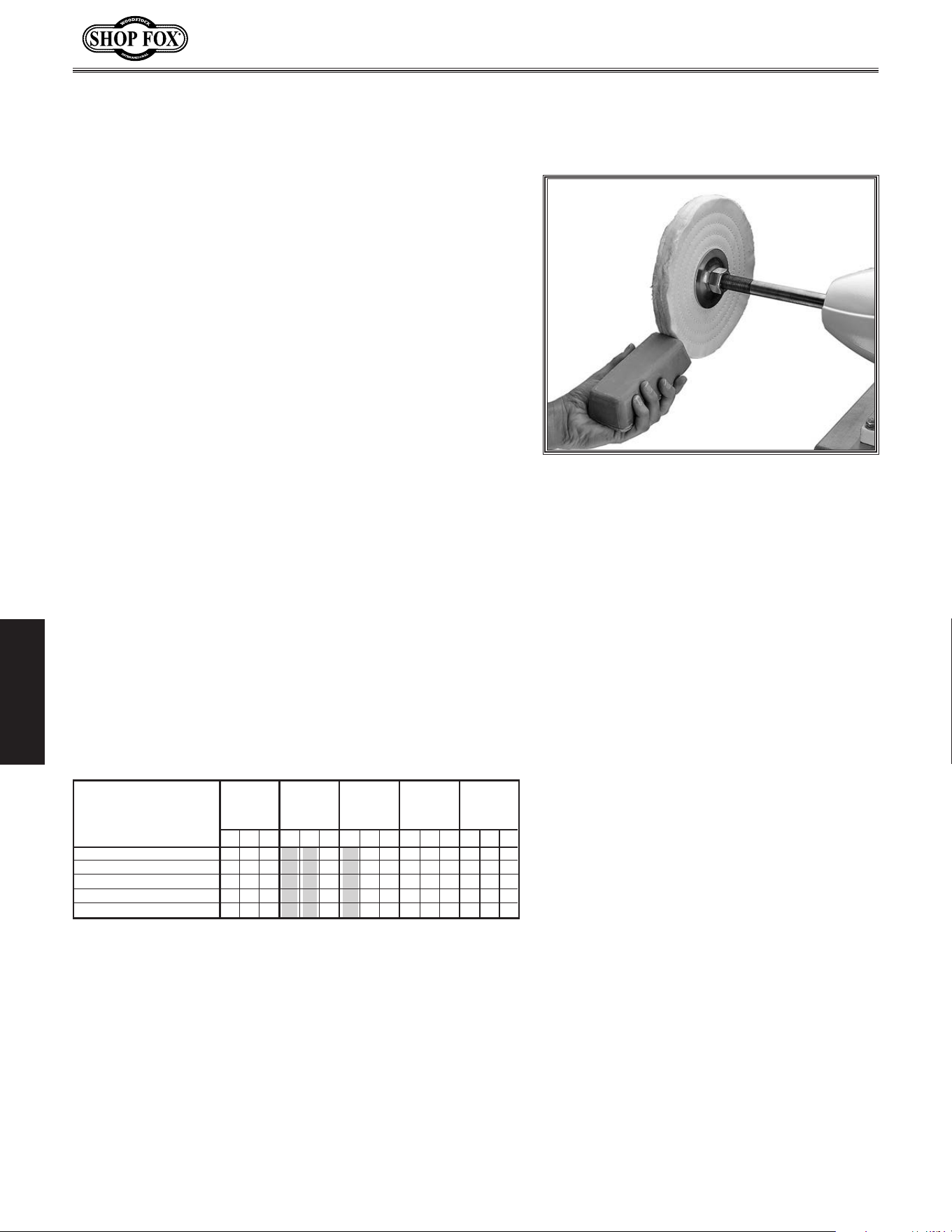
Model W1843 (For Machines Mfd. Since 3/17)
OPERATIONS
Buffing.Wheel.Selection
Buffing wheels are available for most types of metals
and for different stages in the buffing process. Below are
pictures and descriptions of common wheel types:
Buffing Sequence: R = Rough F= Final Cut, Initial Polish P = Final Polish
Spiral Sewn
Plastics
Soft
Metals
Thin
Plating
Gold
Silver
Chrome
&
Nickel
Plate
Copper
Brass
Aluminum
Iron
Steel
Stainless
Buff Style
Loose Muslin-Soft
Loose Muslin-Hard
Airway Hard
Airway Soft
Laminated Sisal
R F P R F P R F P R F P R F P
X
X
X
X
X
X
X
X
X
X
X X
X
X
X
X
X
X XX
Airway Hard
Made of 100% cotton sheets
that are treated to stiffen the
material. Pleats in the materi-
al help hold compound. These
are great for rough cutting
plastics and initial polishing a
wide variety of metals.
Loose Muslin
Soft feather-edged muslin
stitched together near the cen-
ter leaves the outer edge to
provide a wide angle, fine pol-
ishing surface. Perfect for pol-
ishing stainless steel, chrome,
gold or silver.
Laminated Sisal
Designed for rough cutting,
sisal works well with various
steels, copper, aluminum,
and brass to remove scratches
and prepare the piece for
polishing.
Airway Soft
Made of 100% cot-
ton sheets and
held together with
a steel retainer.
Pleats in the mate-
rial help hold com-
pound. These
wheels are great
for polishing soft
metals and plas-
tics.
Spiral Sewn
Consist of layers of
100% unbleached
cotton sheeting
that are spiral
sewn
1
⁄8" apart.
Works well for ini-
tial polish on brass,
stainless steel, alu-
minum, bronze and
cast iron.
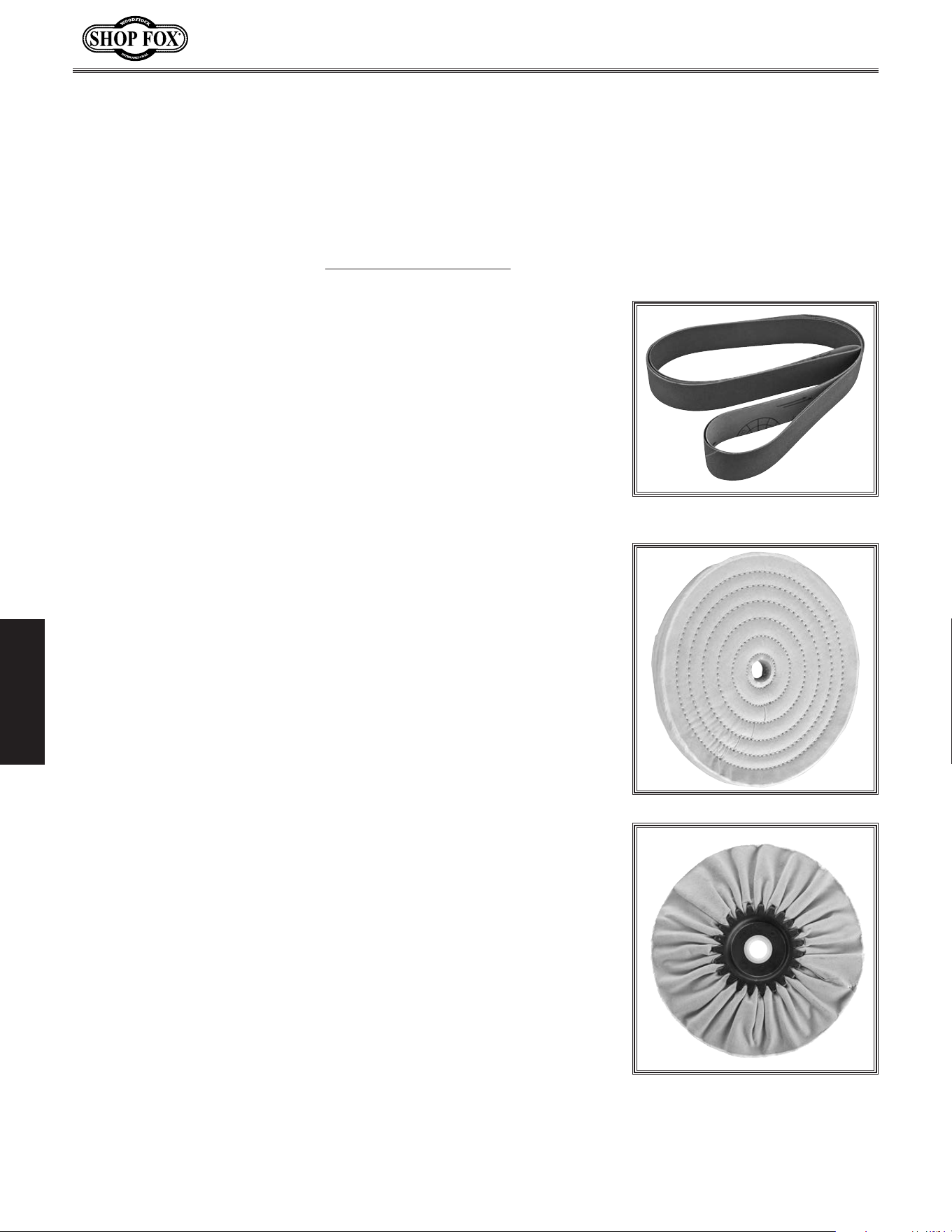
-32-
Model W1843 (For Machines Mfd. Since 3/17)
OPERATIONS
ACCESSORIES
Sander/Buffer.Accessories
The following sander/buffer accessories may be available through your local Woodstock International
Inc. Dealer. If you do not have a dealer in your area, these products are also available through online
dealers. Please call or e-mail Woodstock International Inc. Customer Service to get a current listing of
dealers at: 1-800-840-8420 or at sales@woodstockint.com.
Shop Fox Aluminum Oxide Sanding Belts are available in a wide range
of grit options for your wood sanding needs. Each belt measures 2" x
72" and are sold in a 2-pack.
D1221 – 60-Grit
D1222 – 80-Grit
D1223 – 100-Grit
D1224 – 120-Grit
D1225 – 150-Grit
D1226 – 180-Grit
D1227 – 220-Grit
Bring your soft and delicate metal workpiece to a fine polish with
our selection of Loose Muslin Buffing Wheels. Soft feathered edge
muslin is concentrically stitched near the center, leaving the outer
edge to provide a deep, lustrous shine. Perfect for stainless steel,
chrome, gold, or silver.
D3186 – 3"D x 40 Ply x
5
⁄8" Bore
D3187 – 4"D x 40 Ply x
5
⁄8" Bore
D3188 – 5"D x 40 Ply x
5
⁄8" Bore
D3189 – 6"D x 40 Ply x
5
⁄8" Bore
D3190 – 8"D x 40 Ply x
5
⁄8" Bore
D3191 – 6"D x 50 Ply x
5
⁄8" Bore
D3192 – 8"D x 50 Ply x
5
⁄8" Bore
Treated to provide stiffness, these 100% cotton wheels are perfect
for rough and final cuts of plastics, brass and stainless steel.
Reinforced by a metal fastener, the pleats trap the compound while
the airway design makes it possible to reach awkward places.
D3193 – 6" x 12 Ply x
5
⁄8" Bore
D2517 – 8" x 12 Ply x
5
⁄8" Bore
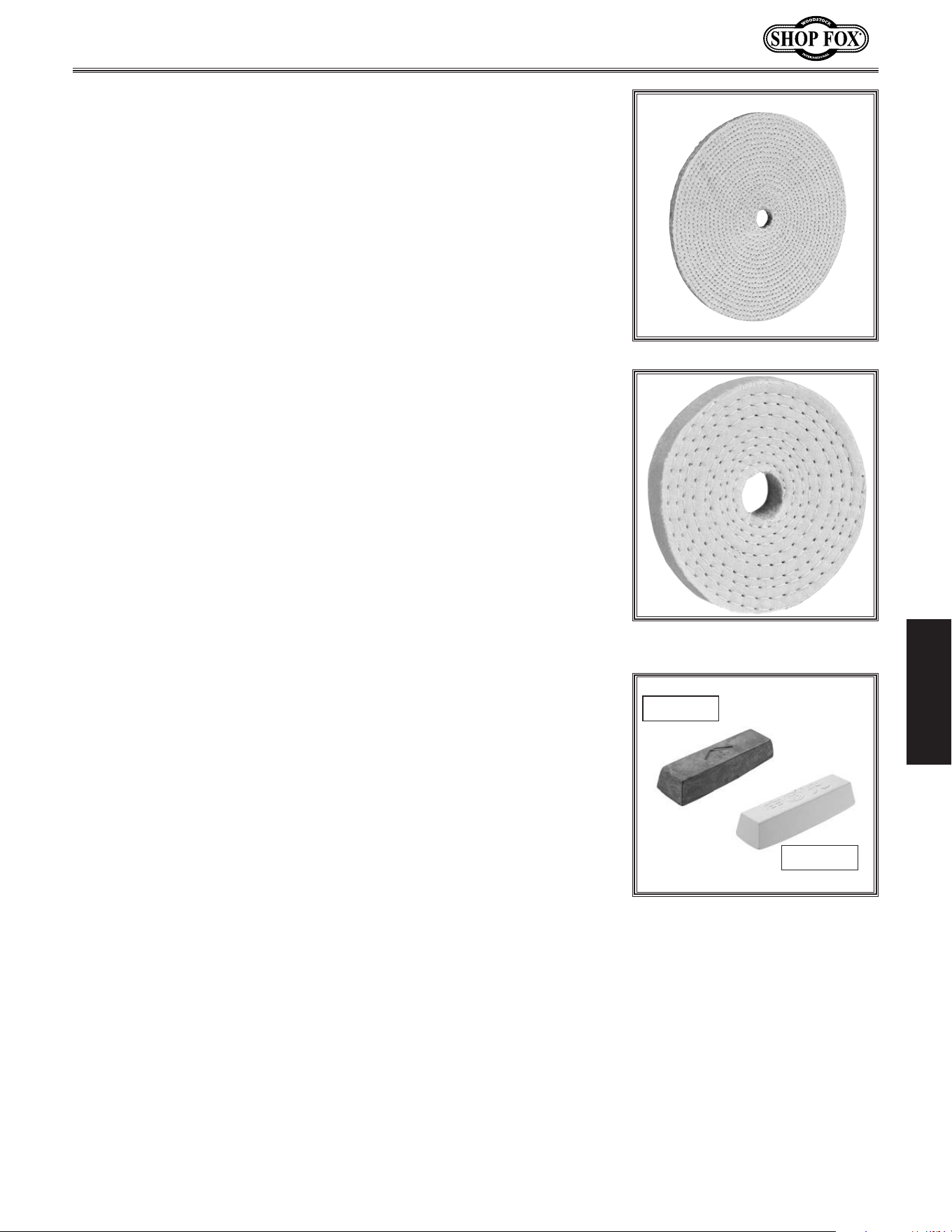
-33-
Model W1843 (For Machines Mfd. Since 3/17)
OPERATIONS
These Spiral Sewn Buffing Wheels are excellent for making the
final cut when polishing plastics and most metals (excluding delicate
metals such as gold and silver). Can be used with any compound.
For final finishing on brass, stainless steel, aluminum, bronze and
cast-iron. Each layer is 100% unbleached cotton sheeting, spiral-sewn
approximately
1
⁄8" apart.
D3175 – 3"D x 40 Ply x
5
⁄8" Bore
D3176 – 4"D x 40 Ply x
5
⁄8" Bore
D3177 – 4"D x 30 Ply x
5
⁄8" Bore
D3181 – 6"D x 40 Ply x
5
⁄8" Bore
D3182 – 8"D x 40 Ply x
5
⁄8" Bore
D3184 – 6"D x 60 Ply x
5
⁄8" Bore
D3185 – 8"D x 40 Ply x
5
⁄8" Bore
The Shop Fox Laminated Hard Sisal Wheel is a popular choice for
finishing various steels (including stainless), copper, aluminum and
brass. Sisal removes small scratches, while the cloth gives a fine
finish.
D3195 – 6" x
1
⁄2" x
5
⁄8" Bore
D2523 – 8" x
1
⁄2" x
5
⁄8" Bore
Shop Fox offers the best Buffing and Polishing Compounds money
can buy. Whether buffing resin, plastics, stainless steel, iron, or
any number of materials, our compounds are great for virtually all
buffing and polishing needs.
D2901 – Red Rouge Buffing Compound (Brass or Gold)
D2902 – Green Extra-Fine Buffing Compound (Most Metals)
D2903 – White Buffing Compound (Plastic, Resin, etc.)
D2904 – Black Buffing Compound (Stainless or Iron)
D2905 – Tripoli Buffing Compound (Brass, Aluminum, etc.)
D2912 – Green Fine Buffing Compound (Softer Metals)
D2912
D2903
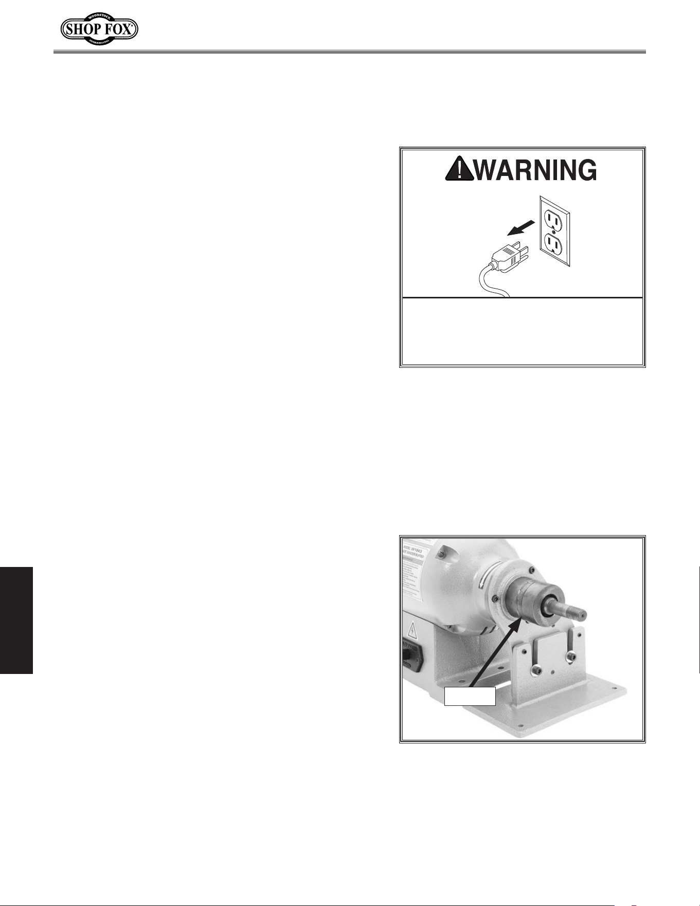
-34-
Model W1843 (For Machines Mfd. Since 3/17)
MAINTENANCE
MAINTENANCE
Cleaning the Model W1843 is relatively easy. Vacuum
excess chips, sawdust, and debris, then wipe off the
remaining dust and grime with a dry cloth. If any resin
has built up, use a resin dissolving cleaner to remove it.
Treat all unpainted cast iron and steel with a non-staining
lubricant after cleaning.
Cleani ng.&.Protecting
Lubrication
For optimum performance from your machine, follow
this maintenance schedule and refer to any specific
instructions given in this section.
Daily Check:
• Loose mounting bolts.
• Damaged or worn sanding belt.
• Worn or damaged wires.
• Any other unsafe condition.
Monthly Check:
• Lubricate pivot arm bushing.
General
The bearings for the Model W1843 were lubricated and
sealed at the factory. Merely leave them alone unless they
need replacement.
To lubricate the pivot arm bushing, remove the sanding
arm assembly and pivot arm, apply a light coat of multi-
purpose grease to the outer surface of the bushing (see
Figure 32), then re-install the components.
MAKE. SURE. that. your. machine. is.
unplugged. during. all. maintenance.
procedures!. If. this. warning. is. ignored,.
serious.personal.injury.may.occur.
Figure 32. Location of pivot arm bushing.
Bushing

-35-
Model W1843 (For Machines Mfd. Since 3/17)
SERVICE
SERVICE
Troubleshooting
Motor.and.Electrical
PROBLEM POSSIBLE.CAUSE CORRECTIVE.ACTION
Machine does not
start or a breaker
trips.
1. Incorrect power supply voltage or circuit size.
2. Power supply circuit breaker tripped or fuse
blown.
3. Motor wires connected incorrectly.
4. Wiring open/has high resistance.
5. ON/OFF button at fault.
6. Motor at fault.
1. Ensure correct power supply voltage and circuit
size.
2. Ensure circuit is sized correctly and free of shorts.
Reset circuit breaker or replace fuse.
3. Correct motor wiring connections.
4. Check/fix broken, disconnected, or corroded wires.
5. Replace button.
6. Test/repair/replace.
Machine stalls or
is underpowered.
1. Machine undersized for task.
2. Motor wired incorrectly.
3. Plug/receptacle at fault.
4. Motor overheated.
5. Motor bearings at fault.
6. Motor at fault.
1. Clean/replace sandpaper; reduce feed rate/sand-
ing depth.
2. Wire motor correctly.
3. Test for good contacts/correct wiring.
4. Clean motor, let cool, and reduce workload.
5. Test by rotating shaft; rotational grinding/loose
shaft requires bearing replacement.
6. Test/repair/replace.
Machine has
vibration or noisy
operation.
1. Motor or component loose.
2. Machine incorrectly mounted to workbench.
3. Motor bearings at fault.
4. Motor shaft bent.
1. Inspect/replace damaged bolts/nuts, and retighten
with thread-locking fluid.
2. Re-tighten mounting bolts; relocate/shim machine.
3. Test by rotating shaft; rotational grinding/loose
shaft requires bearing replacement.
4. Test with dial indicator and replace motor.
The following troubleshooting tables cover common problems that may occur with this machine. If you
need replacement parts or additional troubleshooting help, contact our Technical Support.
Note:
Before contacting Tech Support, find the machine serial number and manufacture date, and if
available, your original purchase receipt. This information is required to properly assist you.

-36-
Model W1843 (For Machines Mfd. Since 3/17)
OPERATIONS
PROBLEM POSSIBLE.CAUSE CORRECTIVE.ACTION
Sanding belt runs
off wheels.
1. Belt tracking not correct.
2. Belt not correctly tensioned.
3. Belt is damaged.
1. Adjust belt tracking (Page 25).
2. Correctly adjust the belt tension (Page 24).
3. Replace belt.
Sanding belt
breaking or
tearing.
1. Belt tension too tight.
2. Belt rotation incorrect.
3. Poor quality/incorrect type belt.
1. Correctly adjust the belt tension (Page 24).
2. Make sure belt is installed with direction arrows
following rotation direction (Page 23).
3. Replace belt with good quality belt of the correct
type for the operation.
Sanding belt
makes grind-
ing noise during
operation.
1. Belt rubbing against wheel housing.
2. Tool rest rubbing against belt.
3. Graphite coating on platen worn out.
4. Idler wheel bearing worn out.
1. Adjust upper wheel guard; correctly adjust belt
tracking (Page 25).
2. Adjust tool rest away from belt no more than
1
⁄16".
3. Replace platen.
4. Replace bearing and idler wheel.
Pivot arm hard to
move.
1. Pivot arm set screws tight.
2. Pivot arm bushing not lubricated.
1. Loosen pivot arm set screws before rotating the
arm (Page 27).
2. Lubricate the pivot arm bushing (Page 34).
Operations
-37-
Model W1843 (For Machines Mfd. Since 3/17)
SERVICE
Elec trical.Safety.Instructions
SHOCK.HAZARD. Working on wiring that is
connected to a power source is extremely
dangerous. Touching electrified parts will
result in personal injury including but not
limited to severe burns, electrocution,
or death. Disconnect the power from
the machine before servicing electrical
components!
QUALIFIED.ELECTRICIAN. Due to the inherent
hazards of electricity, only a qualified
electrician should perform wiring tasks on
this machine. If you are not a qualified
electrician, get help from one before
attempting any kind of wiring job.
WIRE.CONNECTIONS. All connections must
be tight to prevent wires from loosening
during machine operation. Double-check all
wires disconnected or connected during any
wiring task to ensure tight connections.
WIRE/COMPONENT.DAMAGE..Damaged wires
or components increase the risk of serious
personal injury, fire, or machine damage. If
you notice that any wires or components are
damaged while performing a wiring task,
replace those wires or components before
completing the task.
MODIFICATIONS. Using aftermarket parts or
modifying the wiring beyond what is shown
in the diagram may lead to unpredictable
results, including serious injury or fire.
MOTOR.WIRING. The motor wiring shown
in these diagrams is current at the time
of printing, but it may not match your
machine. Always use the wiring diagram
inside the motor junction box.
CAPACITORS/INVERTERS. Some capacitors
and power inverters store an electrical
charge for up to 10 minutes after being
disconnected from the power source.
To reduce the risk of being shocked,
wait at least this long before working on
capacitors.
CIRCUIT.REQUIREMENTS. You MUST follow
the requirements at the beginning of this
manual when connecting your machine to a
power source.
EXPERIENCING.DIFFICULTIES. If you are
experiencing difficulties understanding
the information included in this section,
contact our Technical Support at
(360) 734-3482.
The photos and diagrams
included in this section are
best viewed in color. You
can view these pages in
color at www.shopfox.biz.
BLACK
WHITE
GREEN
RED
BLUE
BROWN
GRAY
ORANGE
YELLOW
YELLOW
GREEN
PURPLE
PINK
LIGHT
BLUE
BLUE
WHITE
TUR-
QUOISE
WIRING DIAGRAM COLOR KEY
These pages are current at the time of printing. However, in the spirit of improvement, we may make
changes to the electrical systems of future machines. Compare the manufacture date of your machine to
the one stated in this manual, and study this section carefully.
If there are differences between your machine and what is shown in this section, call Technical Support
at (360) 734-3482
for assistance BEFORE making any changes to the wiring on your machine. An updated
wiring diagram may be available. Note: Please gather the serial number and manufacture date of your
machine before calling. This information can be found on the main machine label.
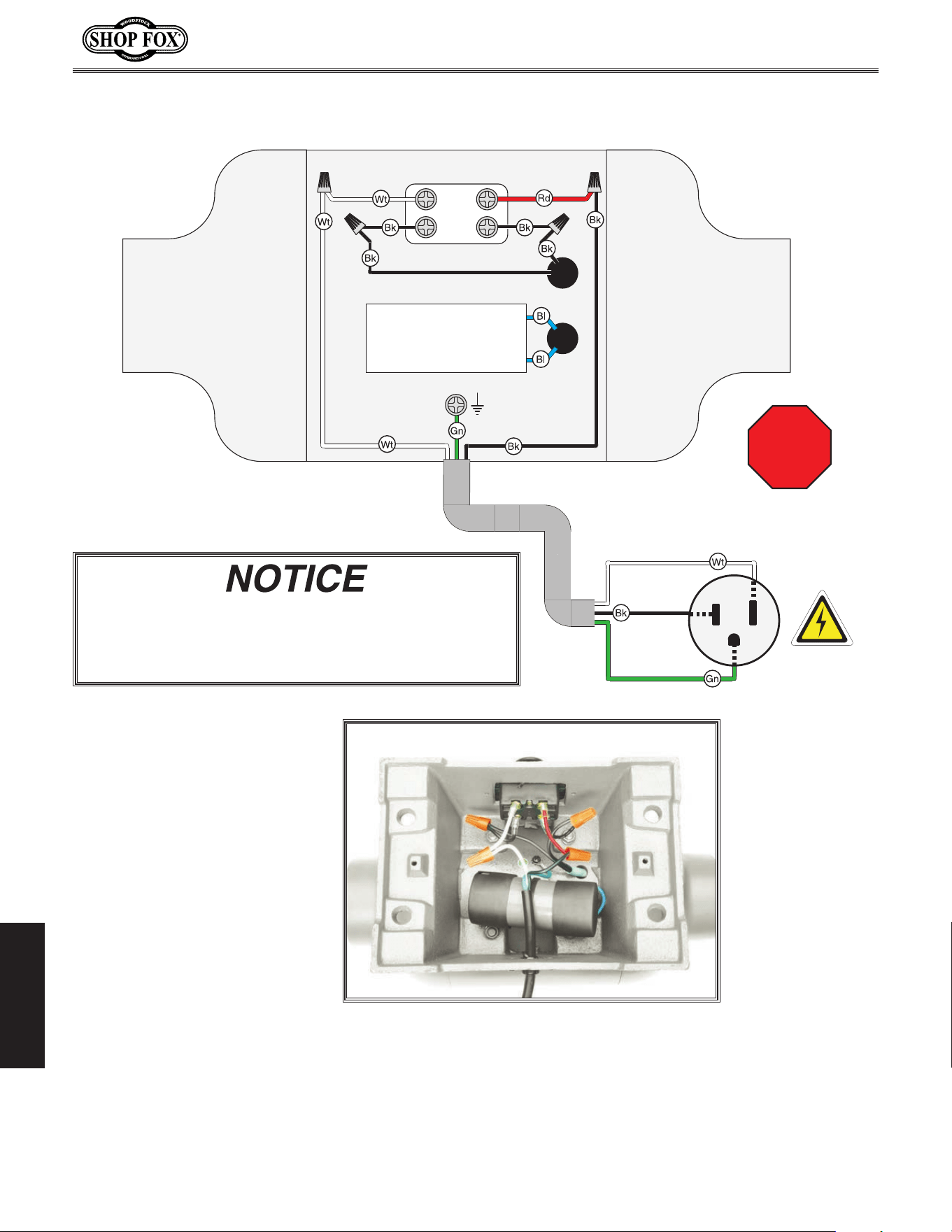
-38-
Model W1843 (For Machines Mfd. Since 3/17)
SERVICE
Motor
ON/OFF Button
Ground
110V NEMA 5-15 Plug
Ground
Hot
Neutral
Start Capacitor
300MFD 125V
101
STOP
Read
Page 39
Before
Wiring
Wiring.Diagram
This.motor.wiring.diagram.is.current.at.the.time.of.
printing;. however,. always. use. the. diagram. on. the.
inside.of.the.junction.box.cover.when.rewiring.your.
motor!
Figure 33. Electrical wiring.
-39-
Model W1843 (For Machines Mfd. Since 3/17)
PARTS
10
6
11
13
14
16
2
3
20
26
27
7
19
12
14
13
16
9
8
1
4
5
21
28
24
17
18
31
29
22
25
23
17-1
15
85
15
PARTS
Motor.Ass embly
REF PART # DESCRIPTION REF PART # DESCRIPTION
1 X1843001 BASE 17 X1843017 CORD BRACKET
2 X1843002 MOTOR CASE 17-1 X1843017-1 STRAIN RELIEF 3/8" TYPE-1
3 X1843003 PHLP HD SCR 5/16-18 X 1-1/4 18 X1843018 PHLP HD SCR 10-24 X 1-1/4
4 X1843004 LOCK WASHER 5/16 19 X1843019 POWER CORD 16G 3W 73"L 5-15P
5 X1843005 HEX NUT 5/16-18 20 X1843020 PULL ON/PUSH OFF SWITCH 20A 250V
6 X1843006 STATOR WINDING 21 X1843021 PHLP HD SCR 10-24 X 1/2
7 X1843007 CONTACT PLATE 22 X1843022 S CAPACITOR 400M 125V 1-3/4 X 3-3/8
8 X1843008 LOCK WASHER #10 23 X1843023 CAPACITOR CAP
9 X1843009 PHLP HD SCR 10-24 X 1/2 24 X1843024 CAPACITOR CLAMP
10 X1843010 ROTOR/SHAFT 25 X1843025 PHLP HD SCR 10-24 X 3/8
11 X1843011 FAN 26 X1843026 BOTTOM PLATE
12 X1843012 CENTRIFUGAL SWITCH 27 X1843027 FLAT WASHER #10
13 X1843013 END COVER 28 X1843028 PHLP HD SCR 10-24 X 3/8
14 X1843014 BALL BEARING 6206ZZ 29 X1843029 WHEEL FLANGE 19.2 X 64.7 X 2.7MM
15 X1843015 LOCK WASHER 1/4 31 X1843031 ARBOR W/COLLAR NUT 5/8-18 LH
16 X1843016 PHLP HD SCR 1/4-20 X 5/8 85 X1843085 MOTOR ASSEMBLY
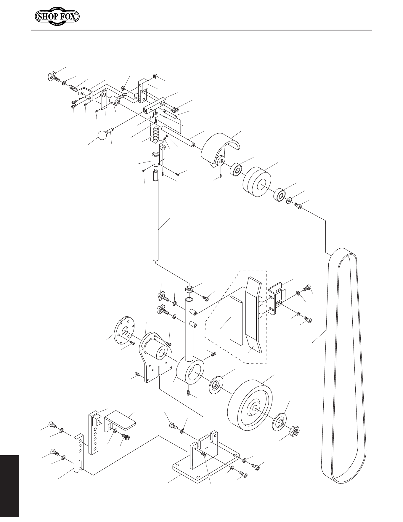
-40-
Model W1843 (For Machines Mfd. Since 3/17)
PARTS
Sanding.Assembly
81
78
79
81
80
86
83
75-1
37
36
37
81
81
74
76
76
81
42
41
40
39
82
73
30
84
32
34
81
81
34
35
35
52
54
53
46
51
47
68
66
50
65
57
56
62
63
43
44
51
48
55
59
49
58
64
67
69
45
77
45
68
72
69
70
71
38
60
61
81
34
75
87
88
87
89
89
33

-41-
Model W1843 (For Machines Mfd. Since 3/17)
PARTS
Sanding.Assembly.Parts.List
REF PART # DESCRIPTION REF PART # DESCRIPTION
30 XP1843030 HEX NUT 3/4-16 61 X1843061 HEX NUT 1/4-20
32 X1843032 PIVOT ARM MOUNTING BRACKET 62 X1843062 SPRING BUSHING
33 X1843033 PIVOT BRACKET W/O BUSHING 63 X1843063 CAP SCREW 1/4-20 X 1
34 X1843034 CAP SCREW 5/16-18 X 1 64 X1843064 AXLE
35 X1843035 SET SCREW 5/16-18 X 1/2 65 X1843065 PIVOT BUSHING
36 X1843036 PIVOT ARM 66 X1843066 SET SCREW 1/4-20 X 3/8
37 X1843037 SET SCREW 3/8-16 X 1/2 67 X1843067 WHEEL GUARD
38 X1843038 SHAFT 1" 68 X1843068 SET SCREW 5/16-18 X 1/4
39 X1843039 KNOB 3/8-16 5-LOBE 69 X1843069 BALL BEARING 6204ZZ
40 X1843040 FLAT WASHER 5/16 70 X1843070 FLAT WASHER 1/4
41 X1843041 COLLAR FOR 1" SHAFT 71 X1843071 CAP SCREW 1/4-20 X 1/2
42 X1843042 CAP SCREW 1/4-28 x 5/8 72 X1843072 IDLER WHEEL
43 X1843043 COMPRESSION SPRING 22 X 87 X 3 73 X1843073 DRIVE WHEEL 10"
44 X1843044 UPPER SHAFT BRACKET 74 X1843074 PLATEN BRACKET
45 X1843045 SET SCREW 5/16-18 X 1/4 75 X1843075 PLATEN
46 X1843046 TRACKING BRACKET 75-1 X1843075-1 GRAPHITE PAD 2"W X 9"L
47 X1843047 CAP SCREW 1/4-20 X 1/2 76 X1843076 CAP SCREW 5/16-18 X 3/4
48 X1843048 PIVOT BRACKET 77 X1843077 ROLL PIN 1/8 X 1
49 X1843049 TENSION BAR SHAFT 78 X1843078 TOOL REST SUPPORT LOWER
50 X1843050 TRACKING LEVER 79 X1843079 TOOL REST SUPPORT UPPER
51 X1843051 LOCK NUT 3/8-16 80 X1843080 CAP SCREW 5/16-18 X 1
52 X1843052 KNOB 1/2-20 6-LOBE 81 X1843081 FLAT WASHER 5/16
53 X1843053 COMPRESSION SPRING 18 X 56 X 2 82 X1843082 CAP SCREW 5/16-18 X 3/4
54 X1843054 FLAT WASHER 1/2 83 X1843083 TOOL REST
55 X1843055 TENSION BAR 4-1/8 X 3/4 X 3/4 84 X1843084 SANDING BELT 2" X 72" 100-GRIT
56 X1843056 TENSION KNOB SHAFT 3/8-16 X 3 86 X1843086 CAP SCREW 5/16-18 X 1-1/4
57 X1843057 TENSION KNOB 1-1/4 87 X1843087 CAP SCREW 1/4-20 X 1/2
58 X1843058 ROLL PIN 5 X 20 88 X1843088 MOUNTING ADAPTER
59 X1843059 CAP SCREW 5/16-18 X 3/4 89 X1843089 WHEEL FLANGE 16.1 X 73.2 X 2.8MM
60 X1843060 SET SCREW 1/4-20 X 5/8
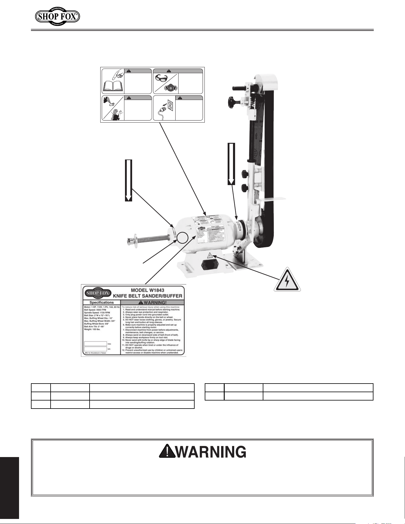
-42-
Model W1843 (For Machines Mfd. Since 3/17)
PARTS
Labels.&.Cosmetics
Safety.labels.warn.about.machine.hazards.and.how.to.prevent.serious.personal.injury..The.owner.
of.this.machine.MUST.maintain.the.original.location.and.readability.of.all.labels.on.this. machine..
If.any.label.is.removed.or.becomes.unreadable,.REPLACE.that.label.before.allowing.machine.to.
be.operated.again..Contact.us.at.(360).734-3482.or.www.woodstockint.com.to.order.new.labels..
EYE/LUNG INJURY
HAZARD!
Always wear safety
glasses and a
respirator when
using this machine.
WARNING!
WARNING!
ENTANGLEMENT
HAZARD!
Tie back long hair, roll up
long sleeves, and remove
loose clothing, jewelry, or
gloves to prevent getting
caught in moving parts.
WARNING!
DISCONNECT
POWER BEFORE
ADJUSTMENTS,
MAINTENANCE,
OR SERVICE.
COPYRIGHT © GRIZZLY INDUSTRIAL, INC.
FOR GRIZZLY MACHINES ONLY! DO NOT REPRODUCE OR CHANGE THIS ARTWORK
WITHOUT WRITTEN APPROVAL!
Grizzly will not accept labels changed without approval.
artwork changes are required, contact us immediately at [email protected]
G1015 Machine Labels B (12/2/16)
• Scale= 1:1 (unless otherwise noted)
• Labels MUST be made of chemical-resistant material
***IMPORTANT***: Labels marked *** have changed since last sending.
PANTONE 151 C or RAL 2005
WARNING
CAUTION
PANTONE 109 C
COLOR CODES
To reduce risk of death
or serious injury, read
manual BEFORE using
machine.
To get a new manual, call
(800) 523-4777 or go to
www.grizzly.com.
WARNING!
COPYRIGHT © WOODSTOCK INTERNATIONAL, INC.
FOR SHOP FOX MACHINES ONLY! DO NOT REPRODUCE OR CHANGE THIS ARTWORK
WITHOUT WRITTEN APPROVAL!
Woodstock will not accept labels changed without
approval. If artwork changes are required, contact us immediately at
MODEL W1843
KNIFE BELT SANDER/BUFFER
Specifications
Motor: 1 HP, 110V, 1-Ph, 14A, 60 Hz
Belt Speed: 3600 FPM
Spindle Speed: 1725 RPM
Belt Size: 2"W x 72"–76"L
Max. Buffing Wheel Dia.: 10"
Max. Buffing Wheel Width: 3/4"
Buffing Wheel Bore: 5/8"
Belt Arm Tilt: 0°–90°
Weight: 105 lbs.
To reduce risk of serious injury when using this machine:
1. Read and understand manual before starting machine.
2. Always wear eye protection and respirator.
3. Only plug power cord into grounded outlet.
4. Never place hands directly on the belt or wheel.
5. DO NOT wear loose clothing, gloves, or jewelry. Secure
long hair and button all long sleeves.
6. Make sure machine is properly adjusted and set up
correctly before starting motor.
7. Disconnect machine from power before adjustments,
maintenance, belt changes, or service.
8. Always sand on downward side of belt (front of belt).
9. Always keep workpiece firmly on tool rest.
10. Never sand with knife tip or sharp edge of blade facing
into sanding/buffing rotation.
11. DO NOT operate when tired or under the influence of
drugs or alcohol.
;sresudeniartnuronerdlihcybesudezirohtuanutneverP.21
restrict access or disable machine when unattended.
WARNING!
Date
S/N
Mfd. for Woodstock in Taiwan
W1843 Machine Labels
(04/04/17)
• Scale= 1:1
(unless otherwise noted)
• Labels MUST be made of
chemical-resistant material
COLOR CODES
PANTONE 151 C or RAL 2005
WARNING
SF LOGO RED
PANTONE 1795C
SF LOGO YELLOW
PANTONE 600C
EYE/LUNG INJURY
HAZARD!
Always wear safety
glasses and a
respirator when
using this machine.
WARNING!
WARNING!
ENTANGLEMENT
HAZARD!
Tie back long hair, roll up
long sleeves, and remove
loose clothing, jewelry, or
gloves to prevent getting
caught in moving parts.
WARNING!
DISCONNECT
POWER BEFORE
ADJUSTMENTS,
MAINTENANCE,
OR SERVICE.
READ and UNDERSTAND
MANUAL to avoid serious
injury! If a manual is not
available, DO NOT use
machine! Instead, go to
www.woodstockint.com
or call
(
360
)
734-3482.
WARNING!
COPYRIGHT © WOODSTOCK INTERNATIONAL, INC.
DO NOT REPRODUCE OR CHANGE THIS ARTWORK
Woodstock will not accept labels changed without
If artwork changes are required, contact us immediately at
MODEL W1843
KNIFE BELT SANDER/BUFFER
To reduce risk of serious injury when using this machine:
1. Read and understand manual before starting machine.
2. Always wear eye protection and respirator.
3. Only plug power cord into grounded outlet.
4. Never place hands directly on the belt or wheel.
5. DO NOT wear loose clothing, gloves, or jewelry. Secure
long hair and button all long sleeves.
6. Make sure machine is properly adjusted and set up
correctly before starting motor.
7. Disconnect machine from power before adjustments,
maintenance, belt changes, or service.
8. Always sand on downward side of belt (front of belt).
9. Always keep workpiece firmly on tool rest.
10. Never sand with knife tip or sharp edge of blade facing
into sanding/buffing rotation.
11. DO NOT operate when tired or under the influence of
drugs or alcohol.
;sresudeniartnuronerdlihcybesudezirohtuanutneverP.21
restrict access or disable machine when unattended.
WARNING!
W1843 Machine Labels
(04/04/17)
• Scale= 1:1
(unless otherwise noted)
• Labels MUST be made of
chemical-resistant material
COLOR CODES
PANTONE 151 C or RAL 2005
WARNING
SF LOGO RED
PANTONE 1795C
SF LOGO YELLOW
PANTONE 600C
EYE/LUNG INJURY
HAZARD!
Always wear safety
glasses and a
respirator when
using this machine.
WARNING!
WARNING!
ENTANGLEMENT
HAZARD!
Tie back long hair, roll up
long sleeves, and remove
loose clothing, jewelry, or
gloves to prevent getting
caught in moving parts.
WARNING!
DISCONNECT
POWER BEFORE
ADJUSTMENTS,
MAINTENANCE,
OR SERVICE.
READ and UNDERSTAND
MANUAL to avoid serious
injury! If a manual is not
available, DO NOT use
machine! Instead, go to
www.woodstockint.com
734-3482.
WARNING!
COPYRIGHT © WOODSTOCK INTERNATIONAL, INC.
FOR SHOP FOX MACHINES ONLY! DO NOT REPRODUCE OR CHANGE THIS ARTWORK
WITHOUT WRITTEN APPROVAL!
Woodstock will not accept labels changed without
approval. If artwork changes are required, contact us immediately at
restrict access or disable machine when unattended.
S/N
Mfd. for Woodstock in Taiwan
COLOR CODES
PANTONE 151 C or RAL 2005
WARNING
SF LOGO RED
PANTONE 1795C
SF LOGO YELLOW
PANTONE 600C
EYE/LUNG INJURY
HAZARD!
Always wear safety
glasses and a
respirator when
using this machine.
WARNING!
WARNING!
ENTANGLEMENT
HAZARD!
Tie back long hair, roll up
long sleeves, and remove
loose clothing, jewelry, or
gloves to prevent getting
caught in moving parts.
WARNING!
DISCONNECT
POWER BEFORE
ADJUSTMENTS,
MAINTENANCE,
OR SERVICE.
READ and UNDERSTAND
MANUAL to avoid serious
injury! If a manual is not
available, DO NOT use
machine! Instead, go to
www.woodstockint.com
or call
(
360
)
734-3482.
WARNING!
101
102
103
104
105
102
REF PART # DESCRIPTION REF PART # DESCRIPTION
101 X1843101 COMBO WARNING LABEL 104 X1843104 MACHINE ID LABEL
102 X1843102 ROTATION DIRECTION LABEL 105 X1843105 TOUCH-UP PAINT, SHOP FOX WHITE
103 X1843103 ELECTRICITY LABEL


tape along edges--please do not staple
Fold along dotted lIne
Fold along dotted lIne
Woodstock international inc.
p.o. box 2309
bellingham, Wa 98227-2309
place
stamp
Here

WARRANTY
Woodstock International, Inc. warrants all Shop Fox machinery to be free of defects from workmanship
and materials for a period of two years from the date of original purchase by the original owner.
This warranty does not apply to defects due directly or indirectly to misuse, abuse, negligence or
accidents, lack of maintenance, or reimbursement of third party expenses incurred.
Woodstock International, Inc. will repair, replace, or arrange for a dealer refund, at its expense and
option, the Shop Fox machine or machine part proven to be defective for its designed and intended
use, provided that the original owner returns the product prepaid to an authorized warranty or repair
facility as designated by our Bellingham, Washington office with proof of their purchase of the product
within two years, and provides Woodstock International, Inc. reasonable opportunity to verify the
alleged defect through inspection. If it is determined there is no defect, or that the defect resulted
from causes not within the scope of Woodstock International Inc.'s warranty, then the original owner
must bear the cost of storing and returning the product.
This is Woodstock International, Inc.’s sole written warranty and any and all warranties that may be
implied by law, including any merchantability or fitness, for any particular purpose, are hereby limited
to the duration of this written warranty. We do not warrant that Shop Fox machinery complies with
the provisions of any law, acts or electrical codes. We do not reimburse for third party repairs. In no
event shall Woodstock International, Inc.’s liability under this limited warranty exceed the purchase
price paid for the product, and any legal actions brought against Woodstock International, Inc. shall be
tried in the State of Washington, County of Whatcom. We shall in no event be liable for death, injuries
to persons or property or for incidental, contingent, special or consequential damages arising from the
use of our products.
Every effort has been made to ensure that all Shop Fox machinery meets high quality and durability
standards. We are commited to continuously improving the quality of our products, and
reserve the
right to change specifications at any time
.
WARRANTY

High Quality Machines and Tools
Woodstock International, Inc. carries thousands of products designed
to meet the needs of today's woodworkers and metalworkers.
Ask your dealer about these fine products: