

These instructions accompanying the product are the original instructions. This document is part of the product, keep
it for the life of the product passing it on to any subsequent holder of the product. Read all these instructions before
assembling, operating or maintaining this product.
This manual has been compiled by Draper Tools describing the purpose for which the product has been designed,
and contains all the necessary information to ensure its correct and safe use. By following all the general safety
instructions contained in this manual, it will ensure both product and operator safety, together with longer life of the
product itself.
All photographs and drawings in this manual are supplied by Draper Tools to help illustrate the operation of the
product.
Whilst every effort has been made to ensure the accuracy of information contained in this manual, the Draper Tools
policy of continuous improvement determines the right to make modifications without prior warning.
230V OSCILLA TING
SPINDLE AND BELT
SANDER
98425

– 2 –
1.1 INTRODUCTION:
USER MANUAL FOR: 230V Oscillating Spindle and Belt Sander
Stock No: 98425
Part No: OSBS450D
1.2 REVISIONS:
Date first published March 2021.
As our user manuals are continually updated, users should make
sure that they use the very latest version.
Downloads are available from: http://drapertools.com/manuals
Draper Tools Limited
Hursley Road
Chandler’s Ford
Eastleigh
Hampshire
SO53 1YF
UK
Website: drapertools.com
Product Help Line: +44 (0) 23 8049 4344
General Fax: +44 (0) 23 8026 0784
1.3 UNDERSTANDING THIS MANUALS SAFETY CONTENT:
Warning! – Information that draws attention to the risk of injury or death.
Important – Information that draws attention to the risk of damage to the product or surroundings.
1.4 COPYRIGHT © NOTICE:
Copyright © Draper Tools Limited.
Permission is granted to reproduce this publication for personal and educational use only.
Commercial copying, redistribution, hiring or lending is prohibited.
No part of this publication may be stored in a retrieval system or transmitted in any other form or
means without written permission from Draper Tools Limited.
In all cases this copyright notice must remain intact.
1. TITLE PAGE

– 3 –
2.1 TABLE OF CONTENTS
2. CONTENTS
1. TITLE PAGE
1.1 INTRODUCTION .......................................................................................................... 2
1.2 REVISIONS .................................................................................................................. 2
1.3 UNDERSTANDING THIS MANUALS SAFETY CONTENT ......................................... 2
1.4 COPYRIGHT © NOTICE .............................................................................................. 2
2. CONTENTS
2.1 TABLE OF CONTENTS ............................................................................................... 3
3. WARRANTY
3.1 WARRANTY ................................................................................................................. 4
4. INTRODUCTION
4.1 SCOPE ......................................................................................................................... 5
4.2 SPECIFICATION .......................................................................................................... 5
4.3 HANDLING AND STORAGE ........................................................................................ 5
5. HEALTH AND SAFETY INFORMATION
5.1 GENERAL SAFETY INSTRUCTIONS FOR POWER TOOL USE ............................... 6
5.2 OSCILLATING SPINDLE & BELT SANDER SAFETY ............................................7-8
5.3 ADDITIONAL SAFETY INSTRUCTIONS FOR SANDERS ....................................... 8-9
5.4 RESIDUAL RISK .......................................................................................................... 9
5.5 CONNECTION TO THE POWER SUPPLY.................................................................. 9
6. TECHNICAL DESCRIPTION
6.1 IDENTIFICATION ....................................................................................................... 10
7. UNPACKING AND CHECKING
7.1 PACKAGING .............................................................................................................. 11
7.2 WHAT’S IN THE BOX ................................................................................................ 11
8.
PREPARING THE SANDER
8.1 TOOL HOLDERS ....................................................................................................... 12
8.2 BOBBIN STORAGE ................................................................................................... 12
8.3 INSERTS STORAGE ................................................................................................. 12
8.4 NO-VOLT ON/OFF SWITCH ...................................................................................... 12
8.5 BENCH MOUNTING ................................................................................................. 12
9.
OPERATION AND USE
9.1 DUST EXTRACTION ................................................................................................. 13
9.2 BELT SANDER MODE .............................................................................................. 13
9.3 TRACKING ADJUSTMENT ....................................................................................... 14
9.4 SPINDLE SANDER MODE ....................................................................................... 15
9.5 TABLE TILTING ......................................................................................................... 15
10. MAINTENANCE AND TROUBLESHOOTING
10.1 MAINTENANCE ......................................................................................................... 16
10.2 CLEANING ............................................................................................................... 16
10.3 BRUSH REPLACEMENT .......................................................................................... 16
10.4 TROUBLESHOOTING .............................................................................................. 17
11. EXPLANATION OF SYMBOLS
11.1 EXPLANATION OF SYMBOLS .................................................................................. 18
12. DISPOSAL
12.1 DISPOSAL ................................................................................................................. 19
DECLARATION OF CONFORMITY.............................................................................. ENCLOSED

– 4 –
3. WARRANTY
3.1 WARRANTY
Draper tools have been carefully tested and inspected before shipment and are guaranteed to be
free from defective materials and workmanship.
Should the tool develop a fault, please return the complete tool to your nearest distributor or
contact:
Draper Tools Limited, Chandler’s Ford, Eastleigh, Hampshire, SO53 1YF. England.
Telephone Sales Desk: +44 (0) 8049 4333 or Product Help Line +44 (0) 23 8049 4344.
A proof of purchase must be provided with the tool.
If upon inspection it is found that the fault occurring is due to defective materials or workmanship,
repairs will be carried out free of charge. This warranty period covering labour is 12 months from
the date of purchase except where tools are hired out when the warranty period is 90 days from
the date of purchase. The warranty is extended to 24 months for parts only. This warranty does not
apply to any consumable parts, any type of battery or normal wear and tear, nor does it cover any
damage caused by misuse, careless or unsafe handling, alterations, accidents, or repairs
attempted or made by any personnel other than the authorised Draper warranty repair agent.
Note: If the tool is found not to be within the terms of warranty, repairs and carriage charges will
be quoted and made accordingly.
This warranty applies in lieu of any other warranty expressed or implied and variations of its terms
are not authorised.
Your Draper warranty is not effective unless you can produce upon request a dated receipt or
invoice to verify your proof of purchase within the warranty period.
Please note that this warranty is an additional benefit and does not affect your statutory rights.
Draper Tools Limited.

– 5 –
4.1 SCOPE
This oscillating spindle sander is a versatile machine allowing various finishing tasks to be
undertaken.
4.2 SPECIFICATION
Stock No. .................................................................................................................................. 98425
Part No. ............................................................................................................................OSBS450D
Motor:
Rated voltage ................................................................................................................ 230V~
Rated frequency .............................................................................................................. 50Hz
Rated input ..................................................................................................................... 450W
Revolutions per minute ........................................................................................................ 2000rpm
Oscillations per minute .................................................................................................................. 58
Oscillations stroke length ......................................................................................................... 16mm
Sanding sleeves included ......................................................................................13mmØ x 114mm
......................................................................................................................19mmØ x 114mm
..................................................................................................................... 26mmØ x 114mm
..................................................................................................................... 38mmØ x 114mm
..................................................................................................................... 51mmØ x 114mm
Table size ........................................................................... 430 x 410mm, table tilting 220 x 410mm
Table tilt ............................................................................................................... 0-45° tilting section
Belt size ....................................................................................................................... 100 x 610mm
Dust extraction outlet ............................................................................................................... 38mm
Max. spindle working height .................................................................................................. 110mm
Max. spindle height ................................................................................................................ 115mm
Sound pressure level (LpA) .................................................................................................. 76dB(A)
Sound power level (LWA) ...................................................................................................... 89dB(A)
Vibration level ..................................................................................................................... <2.5m/s2
Weight (Nett) .......................................................................................................................... 12.9kg
4.3 HANDLING AND STORAGE
− Care must be taken when handling this product.
• Dropping this power tool could have an effect on its accuracy and could also result in
personal injury. This product is not a toy and must be respected.
− Environmental conditions can have a detrimental effect on this product if neglected.
• Exposure to damp air can gradually corrode components. If the product is unprotected from
dust and debris, components will become clogged.
• If not cleaned and maintained correctly or regularly, the machine will not perform at its best.
4. INTRODUCTION

– 6 –
5. HEALTH AND SAFETY INFORMATION
5.1 GENERAL SAFETY INSTRUCTIONS FOR POWER TOOL USE
WARNING: Read all safety warnings, instructions, illustrations and specifications provided with
this power tool. Failure to follow all instructions listed below may result in electric shock, fire and/or
serious injury.
Save all warnings and instructions for future reference.
The term “power tool” in the warnings refers to your mains-operated (corded) power tool or
battery-operated (cordless) power tool.
Work area safety
Keep work area clean and well lit. Cluttered or dark areas invite accidents.
Do not operate power tools in explosive atmospheres, such as in the presence of flammable
liquids, gases or dust. Power tools create sparks which may ignite the dust or fumes.
Keep children and bystanders away while operating a power tool. Distractions can cause you to
lose control.
Electrical safety
Power tool plugs must match the outlet. Never modify the plug in any way. Do not use any adapter
plugs with earthed (grounded) power tools. Unmodified plugs and matching outlets will reduce risk
of electric shock.
Avoid body contact with earthed or grounded surfaces, such as pipes, radiators, ranges and
refrigerators. There is an increased risk of electric shock if your body is earthed or grounded.
Do not expose power tools to rain or wet conditions. Water entering a power tool will increase the
risk of electric shock.
Do not abuse the cord. Never use the cord for carrying, pulling or unplugging the power tool. Keep
cord away from heat, oil, sharp edges or moving parts. Damaged or entangled cords increase the
risk of electric shock.
When operating a power tool outdoors, use an extension cord suitable for outdoor use. Use of a
cord suitable for outdoor use reduces the risk of electric shock.
If operating a power tool in a damp location is unavoidable, use a residual current device (RCD)
protected supply. Use of an RCD reduces the risk of electric shock.
Personal safety
Stay alert, watch what you are doing and use common sense when operating a power tool. Do
not use a power tool while you are tired or under the influence of drugs, alcohol or medication. A
moment of inattention while operating power tools may result in serious personal injury.
Use personal protective equipment. Always wear eye protection. Protective equipment such as a
dust mask, non-skid safety shoes, hard hat or hearing protection used for appropriate conditions
will reduce personal injuries.
Prevent unintentional starting. Ensure the switch is in the OFF-position before connecting to power
source and/or battery pack, picking up or carrying the tool. Carrying power tools with your finger on
the switch or energising power tools that have the switch ON invites accidents.
Remove any adjusting key or wrench before turning the power tool ON. A wrench or a key left
attached to a rotating part of the power tool may result in personal injury.
Do not overreach. Keep proper footing and balance at all times. This enables better control of the
power tool in unexpected situations.
Dress properly. Do not wear loose clothing or jewellery. Keep your hair and clothing away from
moving parts. Loose clothes, jewellery or long hair can be caught in moving parts.
If devices are provided for the connection of dust extraction and collection facilities, ensure these
are connected and properly used. Use of dust collection can reduce dust-related hazards.
Do not let familiarity gained from frequent use of tools allow you to become complacent and ignore

5. HEALTH AND SAFETY INFORMATION
– 7 –
tool safety principles. A careless action can cause severe injury within a fraction of a second.
Power tool use and care
Do not force the power tool. Use the correct power tool for your application. The correct power tool
will do the job better and safer at the rate for which it was designed.
Do not use the power tool if the switch does not turn it ON and OFF. Any power tool that cannot be
controlled with the switch is dangerous and must be repaired.
Disconnect the plug from the power source and/or remove the battery pack, if detachable, from
the power tool before making any adjustments, changing accessories, or storing power tools. Such
preventive safety measures reduce the risk of starting the power tool accidentally.
Store idle power tools out of the reach of children and do not allow persons unfamiliar with the
power tool or these instructions to operate the power tool. Power tools are dangerous in the hands
of untrained users.
Maintain power tools and accessories. Check for misalignment or binding of moving parts,
breakage of parts and any other condition that may affect the power tool’s operation. If damaged,
have the power tool repaired before use. Many accidents are caused by poorly maintained power
tools.
Keep cutting tools sharp and clean. Properly maintained cutting tools with sharp cutting edges are
less likely to bind and are easier to control.
Use the power tool, accessories and tool bits, etc. in accordance with these instructions, taking
into account the working conditions and the work to be performed. Use of the power tool for
operations different from those intended could result in a hazardous situation.
Keep handles and grasping surfaces dry, clean and free from oil and grease. Slippery handles and
grasping surfaces do not allow for safe handling and control of the tool in unexpected situations.
Service
Have your power tool serviced by a qualified repair person using only identical replacement parts.
This will ensure that the safety of the power tool is maintained.
5.2 OSCILLATING SPINDLE & BELT SANDER SAFETY
WARNING!
Hold the power tool by insulated handles or gripping surfaces only, because the sanding belt/sheet
may contact its own cord. Cutting a “live” wire may make exposed metal parts of the power tool
‘live’ and could give the operator an electric shock.
Recommendation that the tool always be supplied via a residual current device with a rated
residual current of 30 mA or less.
If the replacement of the supply cord is necessary, this has to be done by the manufacturer or his
agent in order to avoid a safety hazard.
The warnings, precautions, and instructions discussed in this manual cannot cover all possible
conditions and situations that may occur. The operator must understand that common sense and
caution are factors which cannot be built into this product, but must be supplied by the operator.
Do not operate the spindle sander until it is fully assembled and you have read and understood the
following instructions and the warning labels on the sander.
Check the condition of the sander. If any part is missing, bent, or does not operate properly,
replace the part before using the sander.
Determine the type of work you are going to be doing before operating the sander.
Secure your work. Support the workpiece securely on the table, and hold it with both hands.
Be aware of the direction of feed. Feed the workpiece into the sanding sleeve or belt against the
direction of rotation of the sanding sleeve or belt.

– 8 –
5.3 ADDITIONAL SAFETY INSTRUCTIONS FOR SANDERS
Safety is a combination of operator common sense and alertness at all times when the sander is
being used.
Warning! For your own safety, do not attempt to operate the oscillating spindle sander until it is
completely assembled and installed according to the instructions and until you have read and
understand the following.
There may be a tendency for the machine to tip over or move during certain operations, due to
this, the sander must be bolted down.
The machine should be positioned so the operator or a casual observer are not forced to stand in
line with the sanding sleeve. This machine is intended for indoor use only.
Always wear safety goggles (not glasses) that comply to a recognised standard. Wear a face mask
if the operation is dusty. Wear ear plugs or muffs during extended periods of operation. Do not
wear gloves, jewellery or watches. Roll long sleeves above the elbow. Tie back long hair.
Do not sand pieces of material too small to hold comfortably by hand.
Avoid awkward hand positions, where a sudden slip could cause a hand to move into the sanding
sleeve.
Never stand on the machine.
Never turn your sander “ON” before clearing the belt table and worktable of all objects.
Make sure the sanding sleeves runs in the right direction. Always have it adjusted correctly so
that the sleeve does not run off the spindle.
Always adjust the worktable to within a maximum of 2mm off the sanding sleeve.
Always keep your hands out of the path of the sander and away from the sanding sleeves or belt.
Avoid hand positions where a sudden slip could cause your hand to contact the sleeve or belt.
Do not reach underneath the workpiece or around the sanding sleeve or belt while the spindle is
rotating.
Disconnect the sander after turning off the power switch. Wait for the spindle to stop rotating
before performing maintenance. The sander must be disconnected when not in use or when
changing throat plates, sanding sleeves, sanding belts, or other items.
Make sure there are no nails or other foreign objects in the area of the workpiece to be sanded.
Never use this sander for wet sanding. Failure to comply may result in electrical shock, causing
serious injury or worse.
Use only identical replacement parts when servicing this sander.
Make sure the spindle has come to a complete stop before touching the workpiece.
Take precautions when sanding painted surfaces. Sanding lead-based paint is NOT
RECOMMENDED. The contaminated dust is too difficult to control, and could cause lead
poisoning.
When sanding paint:
Protect your lungs. Wear a dust mask or respirator.
Do not allow children or pregnant women in the work area until the paint sanding job is finished
and the clean-up is completed
Do not eat, drink, or smoke in an area where painted surfaces are being sanded
Use a dust collection system when possible. Seal the work area with plastic. Do not track paint
dust outside of the work area
Thoroughly clean the area when the paint sanding project is completed
5. HEALTH AND SAFETY INFORMATION

– 9 –
When sanding a large piece of material, provide additional support at table height.
Never leave when the machine is on, wait until the machine has come to a complete stop.
Do not perform assembly or adjustment work on the table while the sander is operating.
Turn sander “OFF” and remove plug from power supply before removing any accessories.
If any part of this oscillating spindle sander breaks, bends, or fails in any way, or any electrical
component fails to perform properly, or if any part is missing, turn off power switch, remove plug
from the power supply and replace damaged, missing and/or failed parts before resuming
operation.
Do not sand with the workpiece unsupported. Support it with the backstop or worktable. The only
exception is curved work performed on the outer end of the belt (idler roller).
Safety is a combination of operator common sense and alertness at all times when the sander is in
operation.
Caution: This oscillating spindle sander is designed solely for wood and nonferrous metals only.
Any other materials will cause damage to the product or risk of fire.
5.4 RESIDUAL RISK
Important: Although the safety instructions and operating manuals for our tools contain extensive
instructions of safe working with power tools, every power tool involves a certain residual risk
which can not be completely excluded by safety mechanisms. Power tools must therefore always
be operated with caution!
5.5 CONNECTION TO THE POWER SUPPLY
Caution: Risk of electric shock. Do not open.
This appliance is supplied with an approved plug and cable for your safety. The value of the fuse
fitted is marked on the pin face of the plug. Should the fuse need replacing, ensure the substitute
is of the correct rating, approved to BS1362 and ASTA or BS Kite marked.
ASTA
BSI
The fuse cover is removable with a small plain slot screwdriver. Ensure the fuse cover is replaced
before attempting to connect the plug to an electrical outlet. If the cover is missing, a replacement
must be obtained or the plug replaced with a suitable type.
If a replacement plug is to be fitted this must be carried out by a qualified electrician.
The damaged or incomplete plug, when cut from the cable should be disabled to prevent
connection to a live electrical outlet.
This appliance is Class II† and is designed for connection to a power supply matching that detailed
on the rating label and compatible with the plug fitted.
If an extension lead is required, use an approved and compatible lead rated for this appliance.
Follow all the instructions supplied with the extension lead.
†Double insulated
: This product requires no earth connection as supplementary insulation is
applied to the basic insulation to protect against electric shock in the event of failure of the basic
insulation.
IMPORTANT: If using an extension lead, follow the instructions that came with your lead
regarding maximum load while cable is wound. If in doubt, ensure that the entire cable is
unwound. Using a coiled extension lead will generate heat which could melt the lead and
cause a fire.
5. HEALTH AND SAFETY INFORMATION

– 10 –
6.1 IDENTIFICATION
6. TECHNICAL DESCRIPTION
(1) Belt Tracking knob
(2) Belt release lever
(3) Workpiece stop
(4) Spindle lock knob
(5) Workpiece stop wing nut
(6) Fixed Table
(7) Throat plate storage
(8) Table angle knob
(9) Table angle gauge
(10)Table angle notches
(11) Bench mounting holes
(12)“OFF” switch
(13)“ON” switch
(14)Washer storage
(15)Drum storage
(16)Tilting table
(17) Belt sander
(18)Dust extraction port
(19)Table angle knob
(20)Throat plate storage
(21)Wrench storage
(22)Rear storage.
(1)
(2)
(3)
(4)
(5)
(6)
(7)
(8)
(9)
(10)
(11)
(12)
(13)
(14)
(15)
(16)
(17)
(18)
(19)
(20)
(21)
(22)

– 11 –
7.1 PACKAGING
Carefully remove the product from the packaging and examine it for any sign of damage that may
have happened during shipping. Lay the contents out and check them against the parts shown
below. If any part is damaged or missing, please contact the Draper Help Line (the telephone
number appears on the Title page) and do not attempt to use the product.
The packaging material should be retained at least during the warranty period, in case the
machine needs to be returned for repair.
Warning!
− Some of the packaging materials used may be harmful to children. Do not leave any of these
materials in the reach of children.
− If any of the packaging is to be thrown away, make sure they are disposed of correctly,
according to local regulations.
7.2 WHAT’S IN THE BOX
As well as the main product, there are several parts not fitted or attached to it.
7. UNPACKING AND CHECKING
(17) Belt sander
(18)Dust extraction port
(19)Table angle knob
(20)Throat plate storage
(21)Wrench storage
(22)Rear storage.
(3) Workpiece stop
(5) Workpiece stop wing nut
(23) Belt sanding unit
(24)Sanding belt
(25)Sanding sleeves (x5 sizes)
(26)Throat plates (x5 sizes)
(27)Spindle nut
(28)Spindle washers
(29)Table insert
(30)Wrench
(31) Sleeve drums (4x sizes)
(32)Spindle
(33)Spindle knob
(34)Dust port adaptor
Note: For details of our full range of accessories and consumables, please visit drapertools.com
(5)
(23)
(24)
(25)
(26)
(3)
(27)
(28)
(29)
(30)
(31)
(33)
(34)
(32)
– 12 –
FIG.1
FIG.2
FIG.3
Note: Remove the plug from the socket before
carrying out adjustment, servicing or maintenance.
8.1 TOOL HOLDERS
The sander comes equipped with two sets of
holders, one for the sanding sleeve and rubber
drums when not in use, the other for the table
inserts.
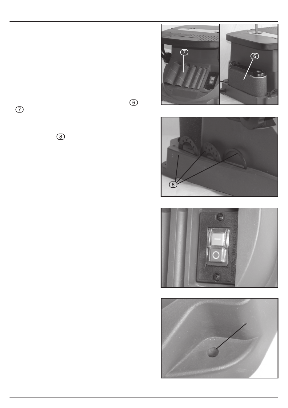
8.2 BOBBIN STORAGE - FIG. 1
Place the sanding sleeve and rubber drums
& onto the storage pins.
8.3 INSERTS STORAGE - FIG. 2
Place the inserts into the storage slots.
8.4 NO-VOLT ON/OFF SWITCH
- FIG. 3
This machine is fitted with a no-volt type
ON/OFF switch.
In the event of a power supply disruption, the
machine will require manually restarting once
power has been returned.
To switch the machine on, press the green button
marked ‘I’.
To switch the machine off, press the red button
marked ‘O’.
8.5 BENCH MOUNTING
Use the bench mounting holes (11)in the base
of the sander to mark and drill 4 x holes into your
intended mounting surface. Secure the spindle
sander into position using large bolts, washers and
nuts (not supplied). If the sander is intended to be
used as a more portable device, fix a board to the
base which can be clamped and removed from
potential mounting surfaces.
Note: Use nylon insert lock nuts or spring washers
when fixing to prevent vibration or loosening of
fittings.
8. PREPARING THE SANDER
FIG.4
(11)
– 13 –
Important: Make sure that the mains voltage matches
the voltage stated on the machines rating plate.
Important: If the sander is to be used in a permanent
position, it is recommended that it is secured to a hard
work surface.
9.1 DUST EXTRACTION - FIG. 5
Inhalation of dust particles can be detrimental to
health. The dust outlet must be connected with a
dust extraction machine.
NOTE: Due to the outlet diameter, a size
adaptation may be necessary.
All wood dust (including dust from composites like
chipboards and fibre boards etc.) is hazardous to
health: it can affect the nose, the respiratory
system and the skin. For example MDF (medium
density fibreboard) which contains formaldehyde is
a known carcinogen. In addition to the above
measures a correctly fitted dust mask, suitable for
the activity and in accordance to the relevant
standard, must be worn.
For work activities involving exposure to fine wood
dust, a mask rated to at least FFP2 should be
used.
Attach the hose to the dust extraction port (18) and
make sure it is connected securely.
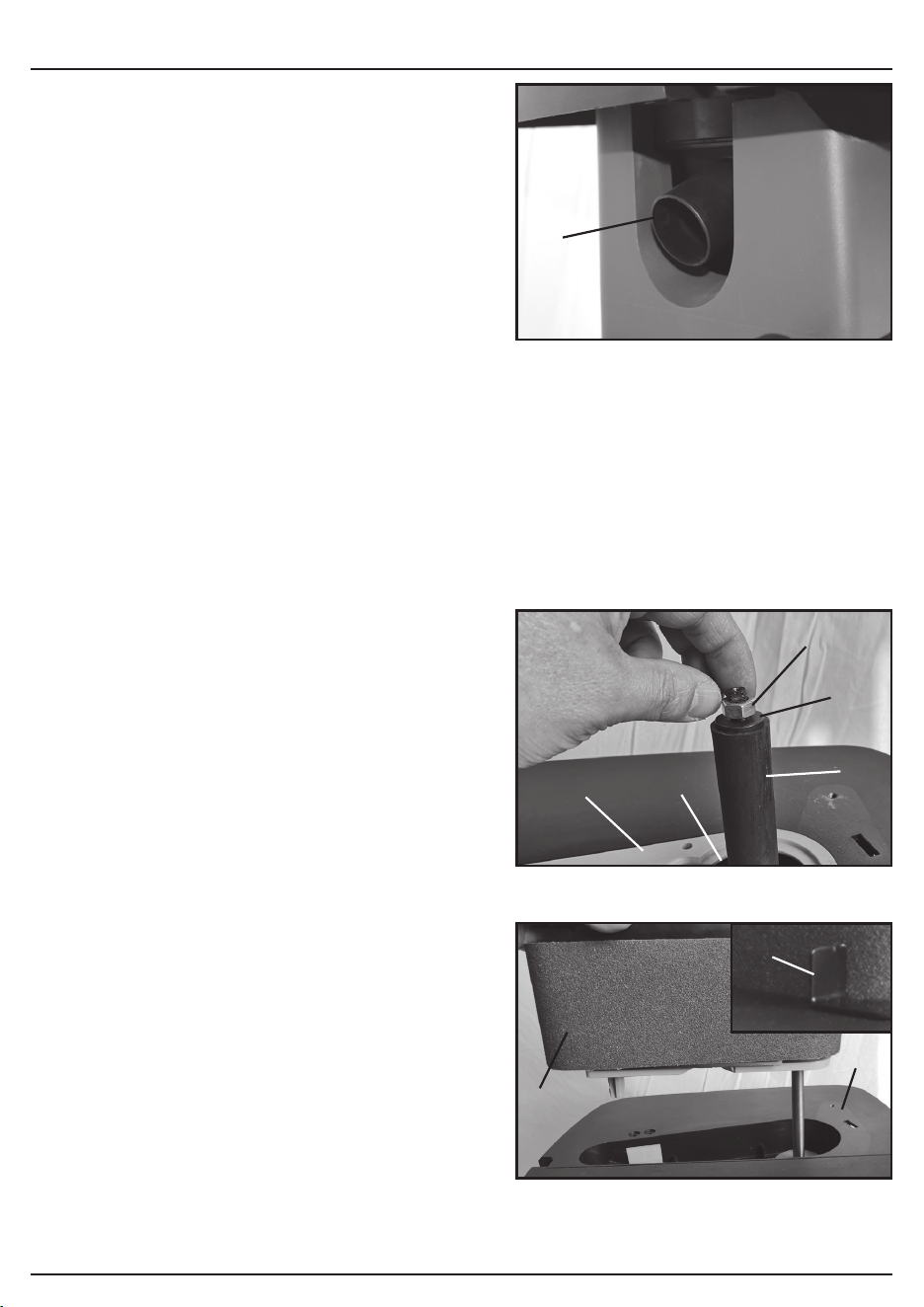
9.2 BELT SANDER MODE - FIGS.
6-10
To remove the spindle components, unscrew the
spindle nut (27) using the wrench supplied and
remove the fitted spindle washer (28), sleeve
drum (31), throat plate (26) and table insert (29).
Store the various spindle components into their
designated storage areas. FIG.6.
Fit the sanding belt unit (23) into the recess
located on the fixed table (6) and secure into
position with the spindle knob (33). FIG.7.
If required, fit the workpiece stop (3) using the
workpiece stop wing nut (5). FIG.7B.
9. OPERATING THE SANDER
FIG.5
FIG.6
FIG.7
(18)
(27)
(28)
(31)
(26)
(29)
FIG.7B
(3)
(23)
(6)
– 14 –
9. OPERATING THE SANDER
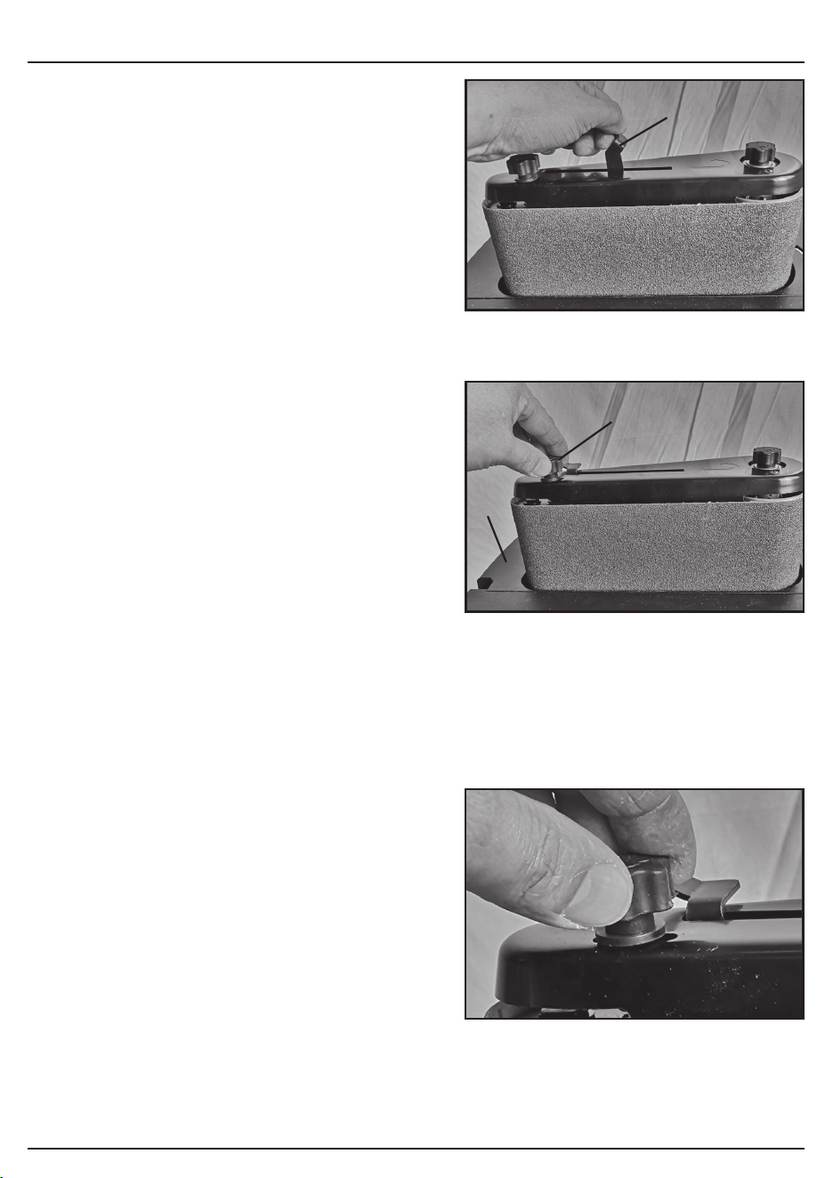
If no sanding belt is fitted, move the belt release
lever (2) towards the spindle knob to allow the belt
to be fitted. Ensure movement is controlled due to
the tensioned spring loaded mechanism avoided
potential damage or injury. FIG.8.
Fit the sanding belt and check that it is lined up
level at the correct height on the main roller of the
belt sanding unit. Ensure the orientation of the belt
is correct and matches the direction of the arrow.
FIG.8.
Move the belt release lever back towards the belt
tracking knob to secure the belt.
Turn the machine on but ensure to check the
tracking of the belt to ensure it runs correctly.
Switch the machine off immediately if the tracking
of the belt is incorrect and it is moving around on
the roller.
9.3
TRACKING ADJUSTMENT - FIG.9
Adjust the belt tracking using the belt tracking knob
(1). If the belt adjusts and moves slowly from its
set position, make small adjustments using the belt
tracking knob. If the tracking is poor each time the
machine is switched off, use the belt release lever
so to re-adjust the belt height to the correct height
before using the belt tracking knob to make
adjustments.
• To increase the height of the belt, turn the belt
tracking knob clockwise. To decrease the height of
the belt, turn anti-clockwise. FIG.10.
• There may be an adjustment range on the belt
tracking knob where the belt tracks consistently.
When tracking, ensure you aim for the middle of
the adjustment range for optimal centralised
tracking even when under load.
NOTE: You risk damaging the belt if it rubs against
the surface in the recess of the fixed table (6) due
to incorrect tracking adjustment. It is more efficient
to adjust the tracking that causes the belt to move
upwards than downwards as when the belt is
moving upwards, it will not damage the edge of the
sanding belt. Ensure you make a large adjustment
clockwise on the belt tracking knob and then
gradual adjusting anti-clockwise to bring the height
back down.
FIG.9
FIG.8
FIG.10
(2)
(1)
(6)
– 15 –
Important: Make sure that the mains voltage matches
the voltage stated on the machines rating plate.
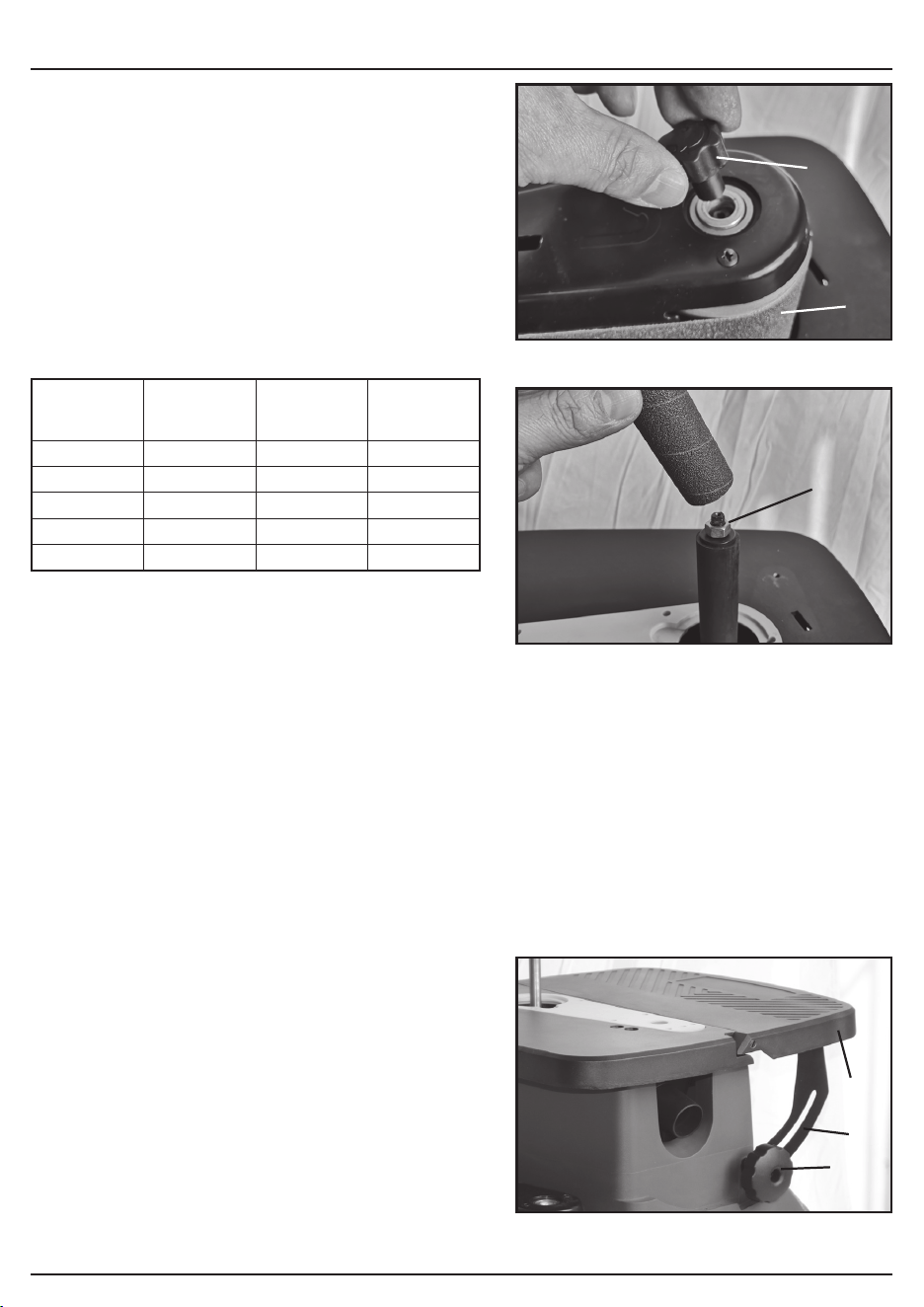
9.4
SPINDLE SANDER MODE
- FIGS. 11 - 12
Remove the belt sander (17) by unscrewing and
removing the spindle knob (33). Lift the belt
sander unit from the fixed table and store in the
rear storage compartment.
Refer to to the throat plate chart below to ensure
correct compatible parts.
Install the spindle sander as shown in Fig.12,
tighten the spindle nut (27) using the wrench
supplied (30) to ensure that the sanding sleeve
does not slip during operation. Do not over-tighten.
NOTE: It is recommended to use the spindle nut
(27), however, if you are frequently changing
between belt and spindle sander modes, the
spindle knob (33) can be used if it proves
adequate compression to hold the sanding sleeve
in place. This depends on the fit of the sleeve and
the drum.
9.5
TABLE TILTING - FIG. 13
The tilting table (16)can be tilted up to 45 degrees.
This allows easy chamferring as well as other edge
work.
• Loosen the 2 x angle knobs (8 & 19) on both
sides of the table.
• Move the table to the required angle position
using the table angle gauge (9). At common angle
positions (0, 15, 22.5, 30 and 45 degrees), there
are lockable click-stop angle notches (10).
9. OPERATING THE SANDER
FIG.11
FIG.13
Sanding
Sleeve (25)
Sleeve
Drum (31)
Throat Plate
(26)
Spindle
Washer
(28)
13mm N/A 13mm Small
19mm Small 10mm Medium
26mm Medium 26mm Medium
38mm Large 38mm Medium
51mm Very Large 51mm Large
THROAT PLATE CHART
FIG.12
(17)
(33)
(27)
(16)
(19)
(9)

– 16 –
10. MAINTENANCE AND TROUBLESHOOTING
10.1 MAINTENANCE
Regular inspection and cleaning reduces the necessity for maintenance operations and will keep
your tool in good working condition.
The motor must be correctly ventilated during tool operation. For this reason avoid blocking the air
inlets. After use disconnect the tool from the power supply and vacuum the ventilation slots.
If the replacement of the supply cord is necessary, this has to be done by the manufacturer or his
agent in order to avoid a safety hazard.
10.2 CLEANING
Remove dust and dirt regularly. Frequently blow or vacuum dust away from all sander parts and
the motor housing
Periodically remove the table insert and lower washer from the spindle and remove any dust
accumulation in the table insert area
Re-lubricate all moving parts at regular intervals
Never use caustic agents to clean plastic parts
Do not use cleaning agents to clean the plastic parts of the tool. A mild detergent on a damp cloth
is recommended. Water must never come into contact with the tool.
10.3 BRUSH REPLACEMENT
Over time the carbon brushes inside the motor may become worn which may cause loss of power,
intermittent failure, or visible sparking.
To replace the brushes;
Place the sander on its side and remove the screws that secure the base cover to allow access to
the motor.
Carefully clean out any accumulated wood dust or chippings by the base cover.
Remove the 2 screws that secure the brush cover and remove cover. Carefully remove brush
assembly.
Disconnect wire attached to brush assembly and remove brush.
Fit replacement brush and reconnect wire.
Replace motor brush assembly ensuring small leg is correctly in place.
Refit brush cover and screws
Repeat steps above with the other brush assembly. It is important to always replace brushes in
pairs.
Re-install and tighten base plate.
Alternatively, have the machine serviced at an authorised service centre.
Important: Please note all repairs/service should be carried out by a qualified person.

– 17 –
10. MAINTENANCE AND TROUBLESHOOTING
10.4 TROUBLESHOOTING GUIDE
Warning! For you own safety always turn the main switch on the machine “OFF” and remove the
plug from the power supply before carrying out any maintenance or troubleshooting.
Problem Possible Cause Remedy
Motor does not start. 1. Defective ON/OFF switch. 1. Replace defective parts
before using again.
2. Burned out motor. 2. Any attempt to repair this
motor may create a
HAZARD unless repair is
done by a qualified
service technician.
Machine slows down when
sanding.
1. Drive belt too tight. 1. Decrease belt tension.
2. Applying too much
pressure to workpiece.
2. Ease up on pressure.
Sanding sleeve does not
rotate with sleeve drum
Spindle nut not tight enough Gradually tighten spindle nut
until sleeve drum secures the
sanding sleeve
Sanding drum not operating
at full speed or motor sounds
different to normal
1. Motor overheating 1. Switch off and allow to
cool for half an hout
2. Motor faulty 2. Contact an advised
service centre
3. Brushes need replacing 3. See “Brush Replacement”
4. Motor belt worn or
stretched
4. Contact an advised
service centre
Sanding belt runs off pulleys. 1. Not tracking properly. 1. Adjust tracking.
A lot of dust is being
produced
1. Dust extractor passage is
blocked
1. Turn machine off at the
mains. Remove the
spindle sander
components or belt
sander unit and remove
the blockage from dust
extractor passage
2. Incorrect throat plate used 2. Use correct size of throat
plate
Wood burns while sanding. 1. Sanding disc or belt is
glazed with sap.
1. Replace disc or belt.

– 18 –
11. EXPLANATION OF SYMBOLS
11.1 EXPLANATION OF SYMBOLS
Read the instruction manual.
Wear face mask and safety
glasses.
Disable the machine before
attempting to maintain it.
WEEE –
Waste Electrical & Electronic Equipment.
Do not dispose of Waste Electrical & Electronic
Equipment in with domestic rubbish.
Double insulated

– 19 –
12.1 DISPOSAL
– At the end of the machine’s working life, or when it can no longer be repaired, ensure that it is
disposed of according to national regulations.
– Contact your local authority for details of collection schemes in your area.
In all circumstances:
• Do not dispose of power tools with domestic waste.
• Do not incinerate.
• Do not dispose of WEEE* as unsorted municipal waste.
* Waste Electrical & Electronic Equipment.
12. DISPOSAL

CONTACTS
Draper Tools Limited, Hursley Road,
Chandler’s Ford, Eastleigh, Hampshire. SO53 1YF. U.K.
Help Line: (023) 8049 4344
Sales Desk: (023) 8049 4333
Internet: drapertools.com
E-mail: [email protected]
General Enquiries: (023) 8026 6355
Service/Warranty Repair Agent:
For aftersales servicing or warranty repairs, please contact the
Draper Tools Help Line for details of an agent in your local area.
YOUR DRAPER STOCKIST
TAFW0321
© Published by Draper Tools Limited.
No part of this publication may be reproduced, stored in a retrieval system or transmitted in any form or by any means,
electronic, mechanical photocopying, recording or otherwise without prior permission in writing from Draper Tools Ltd.