OPERATOR'S MANUAL
MODEL #200947
WALk BEhiND BLOWER
REV 20210430 Champion Power Equipment, Inc., Santa Fe Springs, CA USA
or visit championpowerequipment.com
READ AND SAVE ThiS MANUAL. This manual contains important safety precautions which should be read and understood before operating the product. Failure to
do so could result in serious injury. This manual should remain with the product.
Specifications, descriptions and illustrations in this manual are as accurate as known at the time of publication, but are subject to change without notice.
REGISTER YOUR PRODUCT ONLINE
at championpowerequipment.com
WARNiNG
To reduce the risk of injury, the user must read and understand the operator’s manual before using this product. If you do not
understand the warnings and instructions in the operator’s manual, do not use this product.

2
200947 - WALk BEhiND BLOWER
TABLE Of CONTENTS
TABLE Of CONTENTS
introduction ................................................... 3
Safety Definitions
.......................................... 3
important Safety instructions
....................... 4
Fuel Safety .........................................................6
Safety And Dataplate Labels/Tags ................................7
Safety Symbols .....................................................9
Operation Symbols ............................................... 11
Quickstart Label Symbols........................................ 11
Controls and features ................................. 12
Blower ............................................................ 12
Engine ............................................................ 12
Parts Included .................................................... 13
Parts Not Included ............................................... 13
Assembly ..................................................... 14
Remove the Blower from the Shipping Carton .................. 14
Assemble Front Wheel ........................................... 14
Assemble Upper Handle ......................................... 14
Assemble Throttle Control ....................................... 14
Operation ..................................................... 15
Add Engine Oil .................................................... 15
Add Fuel .......................................................... 16
Starting the Engine ............................................... 17
Stopping the Engine .............................................. 18
Blower Operation ................................................. 19
Before Each Use Inspect the Blower ............................ 19
Adjust the Handle Height ......................................... 19
Vertical Air Flow Adjustment ..................................... 20
Forward Air Flow Attachment ................................... 20
Front Wheel Swivel ............................................... 21
Operation at High Altitude ....................................... 21
Maintenance ................................................ 21
Cleaning the Blower .............................................. 22
Engine Oil Services ............................................... 22
Cleaning and Adjusting the Spark Plug(s) ....................... 23
Cleaning the Air Filter ............................................ 23
Cleaning the Spark Arrestor ..................................... 23
Adjusting the Governor ........................................... 24
Maintenance Schedule ........................................... 24
Storage ........................................................ 24
Short Term Engine Storage (Up to 30 Days) .................... 24
Long Term Engine Storage (30 Days – 1 Year) .................. 24
Specifications .............................................. 26
Blower Specifications ............................................ 26
Engine Specifications ............................................ 26
Spark Plug Specifications ........................................ 26
Valve Specifications .............................................. 26
Oil Specifications ................................................. 26
Fuel Specifications ............................................... 26
Important Message About Temperature......................... 26
Parts Diagram - Figure A ........................................ 27
Parts List - Figure A .............................................. 28
Parts Diagram - Figure B ........................................ 29
Parts List - Figure B .............................................. 30
Engine Parts Diagram ............................................ 31
Engine Parts List ................................................. 32
Troubleshooting ........................................... 34

3
200947 - WALk BEhiND BLOWER
iNTRODUCTiON
iNTRODUCTiON
Congratulations on your purchase of a Champion Power Equipment
(CPE) product. CPE designs, builds, and supports all of our
products to strict specifications and guidelines. With proper
product knowledge, safe use, and regular maintenance, this
product should bring years of satisfying service.
Every effort has been made to ensure the accuracy and
completeness of the information in this manual at the time of
publication, and we reserve the right to change, alter and/or
improve the product and this document at any time without prior
notice.
Since CPE highly values how our products are designed,
manufactured, operated and are serviced, and also highly value
your safety and the safety of others, we would like you to take the
time to review this product manual and other product materials
thoroughly and be fully aware and knowledgeable of the assembly,
operation, dangers and maintenance of the product before use.
Fully familiarize yourself, and make sure others who plan on
operating the product fully familiarize themselves too, with the
proper safety and operation procedures before each use. Please
always exercise common sense and always err on the side
of caution when operating the product to ensure no accident,
property damage, or injury occurs. We want you to continue to use
and be satisfied with your CPE product for years to come.
When contacting CPE about parts and/or service, you will need to
supply the complete model and serial numbers of your product.
Transcribe the information found on your product’s nameplate
label to the table below
CPE TEChNICaL SUPPORT TEam
1-877-338-0999
mODEL NUmBER
200947
SERIaL NUmBER
DaTE OF PURChaSE
PURChaSE LOCaTION
SAfETY DEfiNiTiONS
The purpose of safety symbols is to attract your attention to
possible dangers. The safety symbols, and their explanations,
deserve your careful attention and understanding. The safety
warnings do not by themselves eliminate any danger.
The instructions or warnings they give are not substitutes for
proper accident prevention measures.
DANGER
DANGER indicates a hazardous situation which, if not avoided,
will result in death or serious injury.
WARNiNG
WARNING indicates a hazardous situation which, if not
avoided, could result in death or serious injury.
CAUTiON
CAUTION indicates a hazardous situation which, if not avoided,
could result in minor or moderate injury.
NOTiCE
NOTICE indicates information considered important, but not
hazard-related (e.g., messages relating to property damaged).
4
200947 - WALk BEhiND BLOWER
iMPORTANT SAfETY iNSTRUCTiONS
iMPORTANT SAfETY iNSTRUCTiONS
WARNiNG
Cancer and Reproductive Harm – www.P65Warnings.ca.gov
DANGER
The blower engine exhaust contains carbon monoxide,
a colorless, odorless, poison gas. Breathing carbon monoxide
will cause nausea, dizziness, fainting or death.
If you start to feel dizzy or weak, get to fresh air immediately.
Operate the blower outdoors only in a well ventilated area.
DO NOT operate the blower inside any building, including
garages, basements, crawlspaces and sheds, enclosure or
compartment.
DO NOT allow exhaust fumes to enter a confined area through
windows, doors, vents or other openings.
DANGER
Using an engine indoors CaN KILL YOU IN mINUTES. Engine
exhaust contains carbon monoxide. This is a poison you cannot
see or smell.
NEVER use inside a home or garage, EVEN IF doors and
windows are open.
ONLY use OUTSIDE and far away from windows, doors,
and vents.
Install battery-operated carbon monoxide alarms or plug-in
carbon monoxide alarms with battery back-up according to the
manufacturer’s instructions.
DANGER
Rotating parts can entangle hands, feet, hair, clothing and/or
accessories. Traumatic amputation or severe laceration can
result.
Keep hands and feet away from rotating parts.
Tie up long hair and remove jewelry.
Operate equipment with guards in place.
DO NOT wear loose-fitting clothing, dangling drawstrings or
items that could become caught.
DANGER
DO NOT allow children or untrained individuals to use this unit.
WARNiNG
Maintain a firm grip on the handle with both hands while using
the blower.
WARNiNG
Always wear eye protection with side shields marked to
comply with ANSI Z87.1. Failure to do so could result in objects
being thrown into your eyes and other possible serious injuries.
WARNiNG
Always wear sound protection (ear mufflers or ear plugs) to
protect your hearing. Long term blower noise exposure may
damage your hearing.
WARNiNG
Keep all bystanders, children, and pets at least 50’ (15m) away
when operating the blower.
WARNiNG
Wear heavy long pants, long sleeves, boots, and gloves. Do not
wear loose fitting clothing, short pants, sandals, jewelry of any
kind, or go barefoot.
WARNiNG
To reduce the risk of injury associated with objects being
drawn into rotating parts, do not wear loose clothing, scarves,
neck chains, and the like.
WARNiNG
Secure long hair so it is above shoulder level to prevent
entanglement in any rotating parts.
WARNiNG
Do not operate this unit when you are tired, ill, or under the
influence of alcohol, drugs, or medication.
WARNiNG
Do not operate in poor lighting.

5
200947 - WALk BEhiND BLOWER
iMPORTANT SAfETY iNSTRUCTiONS
WARNiNG
Wear a face filter mask in dusty conditions to reduce the risk
of injury associated with the inhalation of dust.
WARNiNG
Check the work area before each use. Remove all objects such
as rocks (where possible), broken glass, nails, wire, or string
which can be thrown or become entangled in the machine.
WARNiNG
Keep firm footing and balance. Do not overreach. Overreaching
can result in loss of balance or exposure to hot surfaces.
WARNiNG
The engine is equipped with a spark arrestor. Never operate
the unit without a spark arrestor screen.
WARNiNG
Use only identical manufacturer’s replacement parts and
accessories.
WARNiNG
Inspect the unit before each use for loose fasteners, fuel leaks,
etc. Replace damaged parts.
WARNiNG
Rotating impeller blades can cause severe injury. Stop the
engine and ensure impeller blades have stopped rotating
before installing/changing parts or diverters.
WARNiNG
Do not point the blower nozzle in the direction of people or
pets when in operation.
WARNiNG
Spark from a removed spark plug wire can result in fire or
electrical shock.
When servicing the engine:
Disconnect the spark plug wire and place it where it cannot
contact the plug or any other metal object.
DO NOT check for spark with the plug removed.
Use only approved spark plug testers.
WARNiNG
Running engines produce heat. Severe burns can occur on
contact. Combustible material can catch fire on contact.
DO NOT touch hot surfaces.
Avoid contact with hot exhaust gases.
Allow equipment to cool before touching.
Maintain at least 3 ft. (91.4 cm) of clearance on all sides to
ensure adequate cooling.
Maintain at least 5 ft. (1.5 m) of clearance from combustible
materials.

6
200947 - WALk BEhiND BLOWER
iMPORTANT SAfETY iNSTRUCTiONS
WARNiNG
Rapid retraction of the starter cord will pull hand and arm
towards the engine faster than you can let go. Unintentional
startup can result in entanglement, traumatic amputation or
laceration. Broken bones, fractures, bruises or sprains could
result.
When starting engine, pull the starter cord slowly until
resistance is felt and then pull rapidly to avoid kickback.
CAUTiON
Prolonged exposure to vibrations, also known as vibration
white finger, through use of gasoline-powered equipment,
such as this blower, could cause blood vessel or nerve damage
in fingers, hands, and joints. If symptoms occur such as
numbness, or loss of feeling in the fingers, hands, or joints,
discontinue the use of this blower and seek medical attention.
fuel Safety
DANGER
GaSOLINE aND GaSOLINE VaPORS aRE hIGhLY
FLammaBLE aND EXPLOSIVE.
Fire or explosion can cause severe burns or death.
Gasoline and gasoline vapors:
– Gasoline is highly flammable and explosive.
– Gasoline can cause a fire or explosion if ignited.
– Gasoline is a liquid fuel but its vapors can ignite.
– Gasoline is a skin irritant and needs to be cleaned up
immediately if spilled on skin or clothes.
– Gasoline has a distinctive odor, this will help detect potential
leaks quickly.
– In any petroleum gas fire, flames should not be extinguished
unless by doing so the fuel supply valve can be turned OFF.
This is because if a fire is extinguished and a supply of fuel is
not turned OFF, then an explosion hazard could be created.
– Gasoline expands or contracts with ambient temperatures.
Never fill the gasoline tank to full capacity, as gasoline needs
room to expand if temperatures rise.
When adding or removing gasoline:
– DO NOT light or smoke cigarettes.
– Always turn the blower off and let cool for minimum of two
minutes before removing the gasoline cap. Afterwards, loosen
gasoline cap to relieve pressure from the gasoline tank.
– Only fill or drain gasoline outdoors in a well-ventilated area.
– DO NOT pump gasoline directly into the blower at the gas
station. Always use an approved fuel container to transfer the
fuel to the gasoline tank.
– DO NOT overfill the gasoline tank.
– Always keep gasoline away from sparks, open flames, pilot
lights, heat and other sources of ignition.
– Mix and store fuel in a container approved for gasoline.
When starting the blower:
– DO NOT attempt to start a damaged engine.
– Always make certain that the gasoline cap, air filter, spark
plug, fuel lines and exhaust system are properly secured,
connected and in place.
– Always allow spilled gasoline to evaporate fully before
attempting to start the engine.
– Make certain that the blower is resting firmly on level ground.
When operating the blower:
– DO NOT move or tip the blower during operation.
– DO NOT tip the blower or allow fuel or oil to spill.
When storing the blower:
– Store away from sparks, open flames, pilot lights, heat and
other sources of ignition.
– Do not store the blower or gasoline near furnaces, water
heaters, or any other appliances that produce heat or have
automatic ignitions.
WARNiNG
NEVER use a gasoline container, gasoline tank, or any other
fuel item that is broken, cut, torn or damaged.
7
200947 - WALk BEhiND BLOWER
iMPORTANT SAfETY iNSTRUCTiONS
Top viewFront view Back view
A
B
Safety And Dataplate Labels/Tags
These labels warn you of potential hazards that can cause serious injury. Read them carefully.
If a label comes off or becomes hard to read, contact Technical Support Team for possible replacement.
C
LaBEL DESCRIPTION
a
2233-L-SF-A
DANGER DANGER PELIGRO
50 ft.
15m
K 109 186 2945 ---
ColorsLPN 2233-L- SF
Rev A
Size 55 x 177.8 mm
Artwork Notes
5mm corner radius; 2mm safe margin;
to be printed
on
WHITE
substrate.
Revision Changes
---
This ar twork belongs t o Champion Power Eq uipment. The con tents are confi dential and priv ileged and shall not b e disclosed to or us ed by or for
outside p arties withou t the explicit conse nt of Champion Power E quipment.
Blower Housing Danger
Label
B
2222-L-SF-A
DANGER PELIGRO DANGER PELIGRO
50 ft.
15m
485 K --- --- ---
ColorsLPN 2222-L-SF
Rev A
Size 101.6 x 43 mm
Artwork Notes
3mm corner radius; 2mm safe margin;
to be printed
on
WHITE
substrate.
Revision Changes
---
This ar twork belongs to Champion Power Equipment. T he contents are confident ial and privileged and shall not be disclosed to or used by or for
outside parties without the explicit consent of Champion Power Equipment.
Blower Discharge Danger
Label
C
2018-L-OP-A
ESSENCE SANS PLOM SEULEMENT.
Indice d’octane minimal de
87. Maximum 10 % d'éthanol.
La clasificación mínimo de 87
octano. Máximo de etanol de 10%.
GASOLINA SIN PLOMO SOLAMENTE.UNLEADED FUEL ONLY.
Minimum octane rating of 87.
Maximum 10% ethanol.
K 109 --- --- ---
ColorsLPN 2018 -L-OP
Rev B
Size Special
Artwork Notes
3mm corner radius; 2mm safe margin;
to be printed
on
WHITE
substrate.
Revision Changes
-Cha nge octane rati ng 85 to oct ane rat ing 87
(20200409)
This ar twork belongs to Champion Power Equipment. The content s are confiden tial and privileged and shall not be disclosed to or used by or for
outside parties without the explicit consent of C hampion Power Equipment.
Fuel Requirements Label
D
E
f
G
8
200947 - WALk BEhiND BLOWER
iMPORTANT SAfETY iNSTRUCTiONS
LaBEL DESCRIPTION
D
1966-L-SF-A
DO NOT TOUCH!
Hot surface.
WARNING
¡NO TOCAR!
Superficie caliente.
ADVERTENCIA
AVERTISSEMENT
NE TOUCHEZ PAS!
Surface chaude.
K 485 152 --- ---
ColorsLPN 1966-L-SF
Rev A
Size 59 x 47 mm
Artwork Notes
3mm corner radius; 2mm safe margin;
white to be
printed shown in 50% process magenta
Revision Changes
---
This artwork belongs to Champion Power Equipment. The contents are confidential and privileged and shall not be disclosed to or used by or for
outside parties without the explicit consent of Champion Power Equipment.
Hot Surface Warning Label
E
1253-L-SF-A
DANGER PELIGRO DANGER
K 485 2945 109 ---
ColorsLPN 1253-L-SF
Rev A
Size 85 x 35 mm
Artwork Notes
3mm corner radius; 2mm safe margin;
white to be
printed shown in 50% process magenta
Revision Changes
---
This ar twork belongs to Champion Power Equipment. The contents are confidential and privileged and shall not be disclosed to or used by or for
outside parties without the explicit consent of Champion Power Equipment.
Engine Danger Label
F
WARNING
Operation of this equipment may create sparks that can start fires around dry vegetation. A spark arrestor may be required.
The operator should contact local fire agencies for laws or regulations relating to fire prevention requirements.
AVERTISSEMENT
Le fonctionnement de cet équipement peut créer des étincelles qui peuvent déclencher des incendies autour de
la végétation sèche. Un pare-étincelles peut être nécessaire. L'utilisateur doit communiquer avec le service
d'incendie local pour les lois et les règlements relatifs à la prévention des incendies.
2303-L-SF-A
ADVERTENCIA
Operación de este equipo puede crear chispas que pueden iniciar incendios en vegetación seca.
Un parachispas puede ser requerido. El operador debería contactar las agencias locales de incendios para
leyes o regulaciones relacionadas con requisitos de prevención de incendios.
K 152 --- --- ---
ColorsLPN 2303-L-SF
Rev A
Size 133 x 32 mm
Artwork Notes
3mm corner radius; 2mm safe margin
Revision Changes
--
This artwork belongs to Champion Power Equipment. The contents are confidential and privileged and shall not be disclosed to or used by or for
outside parties without the explicit consent of Champion Power Equipment.
Spark Arrestor Warning
Label
G
CHAMPION POWER EQUIPMENT, INC.
12039 SMITH AVENUE
SANTA FE SPRINGS, CA 90670
USA / É.-U.
1-877-338-0999
WWW.CHAMPIONPOWEREQUIPMENT.COM
MADE IN CHINA / FABRIQUÉ EN CHINE
Manufactured to meet ANSI B71.6-2000
2223-L-PR-A
MANUFACTURE DATE
DATE DE FABRICATION
SOUND PRESSURE
PRESSION SONORE
SERIAL NO.
N° DE SÉRIE
MODEL
MODÈLE
200947
85 dB(A)
@ 20 ft. (6 m)
XXXX
XXXXXXXXXXXX
K --- --- --- ---
ColorsLPN 2223 -L-PR
Rev A
Size 51 x 70 mm
Artwork Notes
3mm cor ner radius ; 2mm safe mar gin; to be prin ted
on secu rity subst rate; magen ta text to be fill ed in
durin g time of prod uction
Revision Changes
---
This art work belongs to Cham pion Power Equipment. T he contents are con fidential and privi leged and shall not be disc losed to or used by or for
outside p arties withou t the explicit consen t of Champion Power E quipment.
Product Data Plate Label
9
200947 - WALk BEhiND BLOWER
iMPORTANT SAfETY iNSTRUCTiONS
Safety Symbols
Some of the following symbols may be used on this product. Please study them and learn their meaning. Proper interpretation of these
symbols will allow you to more safely operate the product.
SYmBOL mEaNING
Read Operator’s manual. To reduce the risk of injury, the user must read and understand
the operator’s manual before using this product. If you do not understand the warnings and
instructions in the operator’s manual, do not use this product.
Eye and Ear Protection. Always wear eye protection with side shields marked to comply with
ANSI Z87.1. Failure to do so could result in objects being thrown into your eyes and other possible
serious injuries.
Always wear sound protection (ear mufflers or ear plugs) to protect your hearing. Long term
blower noise exposure may damage your hearing.
Footwear. Always wear safety shoes or heavy boots when operating the machine.
Gloves. Always wear nonslip, heavy-duty protective gloves when operating this product.
Safety alert. Precautions that involve your safety.
Risk of Fire. Fuel and its vapors are extremely flammable and explosive. Fire can cause severe
burns or death. Do not add fuel while the product is operating or still hot.
Open Flame alert. Fuel and its vapors are extremely flammable and explosive. Keep fuel away
from smoking, open flames, sparks, pilot lights, heat, and other ignition sources.
hot Surface. To reduce the risk of injury or damage, avoid contact with any hot surface
10
200947 - WALk BEhiND BLOWER
iMPORTANT SAfETY iNSTRUCTiONS
SYmBOL mEaNING
amputation hazard. Rotating parts can entangle hands, feet, hair, clothing and/or accessories.
Traumatic amputation or severe laceration can result.
Toxic Fumes. The engine exhaust from this product contains chemicals known to the state of
California to cause cancer and birth defects and other reproductive harm.
Risk of asphyxiation. This engine emits carbon monoxide, an odorless, colorless poison gas.
Breathing carbon monoxide can cause nausea, fainting or death. Use only in a well ventilated
area.
Thrown Objects. This machine may pick up and throw objects which can cause personal injury.
Check the work area before each use. Remove all objects such as rocks (where possible), broken
glass, nails, wire, or string which can be thrown or become entangled in the machine.
50 ft.
15m
Clearance. Keep all bystanders, children, and pets at least 50’ (15m) away when operating the
blower.
Never run the unit without the blower fan cover installed. Use of an improperly assembled unit
could result in serious personal injury.
Serious Personal Injury or Property Damage. Before inspecting, cleaning, or servicing the
blower, shut off the engine. Wait for all moving parts to stop, disconnect spark plug wire and
move it away from the spark plug. Failure to follow these instructions could result in personal
injury or damage to the blower.
11
200947 - WALk BEhiND BLOWER
iMPORTANT SAfETY iNSTRUCTiONS
Operation Symbols
Some of the following symbols may be used on this product. Please study them and learn their meaning. Proper interpretation of these
symbols will allow you to more safely operate the product.
SYmBOL mEaNING
Choke/Run
Fuel Valve: CLOSED/OPEN
Throttle Lever
FAST: forward position
Throttle Lever
SLOW: rear position
Quickstart Label Symbols
Some of the following symbols may be used on this product. Please study them and learn their meaning. Proper interpretation of these
symbols will allow you to more safely operate the product.
Starting the Engine
1. Check Oil Level. Recommended oil is 10W-30. The engine
can be seriously damaged without oil. Always check the oil
level before using. The machine must be resting firmly on
level ground when checking.
2. Add gasoline with a minimum octane rating of 87 and an
ethanol content of less than 10% by volume.
3. Move the choke lever to “ChOKE” position.
4. Move the throttle lever, on the handle at the user position,
to the “FaST” position (forward).
5. Move the fuel valve to “OPEN” position.
6. Pull the starter cord slowly until resistance is felt and then
pull rapidly.
7. As engine warms up, move the choke to “RUN”.
SYmBOL mEaNING
Fuel Gauge: Full
Fuel Gauge: Empty
Stop
2197-L-OP-A
1
10W-30
5
1
2
3
7
42
6
186 ---
ColorsLPN 2197-L-OP
Rev A
Size 75 x 35 mm
Artwork Notes
3mm corner radius; 2mm safe margin
Revision Changes
---
This artwork belongs to Champion Power Equipment. The contents are confidential and privileged and shall not be disclosed to or used by or for
outside parties without the explicit consent of Champion Power Equipment.
K 152 CG1
Stopping the Engine
1. Move the fuel valve to the “CLOSED” position.
2. Press the engine switch to the “OFF” position.
12
200947 - WALk BEhiND BLOWER
CONTROLS AND fEATURES
CONTROLS AND fEATURES
Read this operator’s manual before operating your blower. Familiarize yourself with the location and function of the controls and features.
Save this manual for future reference.
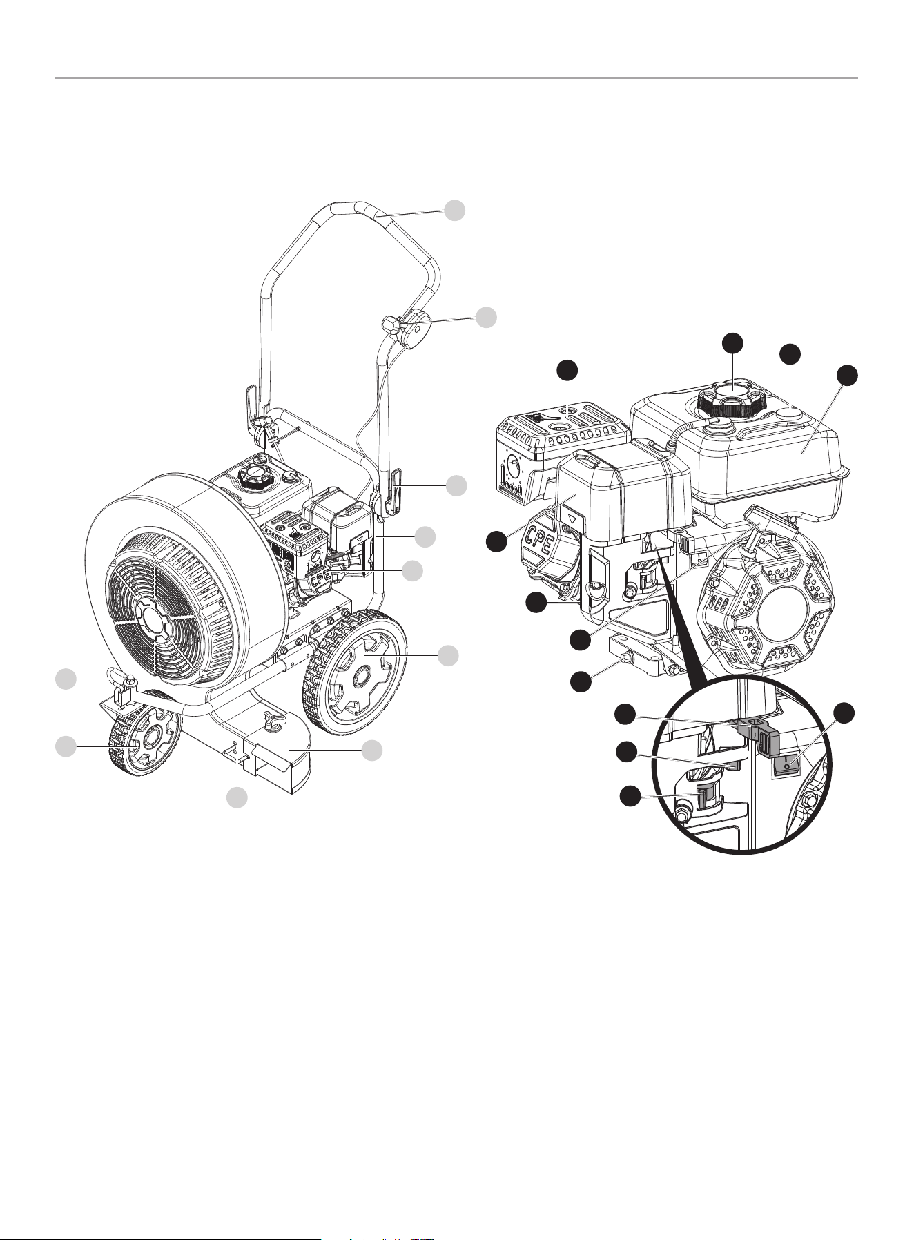
Blower
1. Upper handle
2. Throttle/Speed Control
3. handle adjust Lever
4. Lower handle
5. Engine
6. Rear Wheel
7. Forward air Flow attachment
8. Vertical air Flow adjustment
9. Front Wheel
10. Front Wheel Swivel Lock
2
1
3
4
6
5
7
8
9
10
Engine
1. muffler
2. air Filter
3. Oil Fill Cap/Dipstick
4. Recoil Starter
5. Oil Drain Bolt
6. Throttle
7. Choke
8. Fuel Valve
9. Engine OFF Switch
10. Fuel Tank
11. Fuel Gauge
12. Fuel Tank Cap
1
11
10
12
2
3
5
4
6
7
8
9
13
200947 - WALk BEhiND BLOWER
CONTROLS AND fEATURES
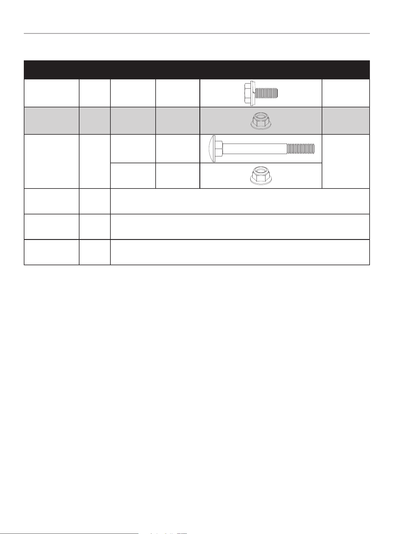
Parts included
Part Part Qty.
hardware
Needed
hardware Qty. hardware Reference Tool Needed
Front wheel 1
M8x20
Hexagon bolt
4
13mm Wrench
Upper handle 1
M8 Nylon
flange lock nut
1
13mm Wrench
Throttle control 1
M6x65 carriage
bolt
1
10mm Wrench
M6 Nylon
flange lock nut
1
Forward flow air
attachment
1 N/A
Engine Oil
16.9 fl. oz (500 ml)
1 N/A
Engine Oil Funnel 1 N/A
Parts Not included
– Metric Wrench or Socket Set
– Phillips Screwdriver
– Pliers
14
200947 - WALk BEhiND BLOWER
ASSEMBLY
ASSEMBLY
Your blower requires some assembly. This unit ships from the
factory without oil. It must be properly serviced with fuel and oil
before operation. For questions regarding the assembly of your
blower, call our help line at 1-877-338-0999. Please have your
serial number and model number available.
Remove the Blower from the Shipping Carton
1. Set the shipping carton on a solid, flat surface.
2. Remove all contents from the carton.
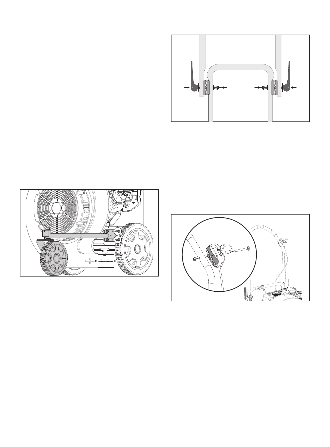
Assemble front Wheel
1. Align the 4 holes on the front wheel bracket with the 4 holes
on the blower frame near the rear wheel on the left side of
the frame (from the user position).
2. Thread a M8 × 20 hex bolt into each hole and, using a 13mm
wrench, tighten to 15 lbf. ft. - 19 lbf. ft.
(20.3 - 25.8 Nm)
Assemble Upper handle
1. Place the upper handle assembly down over the lower handle
assembly, with the upper handle on the outside, and align the
teeth of the upper handle adjuster so they seat into the teeth
on the lower handle adjuster.
2. From the outside of the handle assembly, insert the threaded
end of the handle adjust lever through the hole on the upper
handle assembly and the hole on the lower handle assembly.
3. Thread a M8 nylon lock nut onto the threaded end of the
handle adjust lever. Holding the handle adjust lever in place,
use a 13mm socket or wrench to tighten the lock nut securely
locking the handle in place. (see operation section for handle
height adjustment).
Assemble Throttle Control
1. Align the throttle control to the outside of the upper left
handle (from the user position) with the groove against the
handle and fast speed towards the front.
2. From the outside of the throttle control, place the M6 × 65
carriage bolt through the hole on the throttle and through the
hole on the handle tube.
3. Thread the M6 nylon lock nut onto the bolt and tighten
securely.
15
200947 - WALk BEhiND BLOWER
OPERATiON
OPERATiON
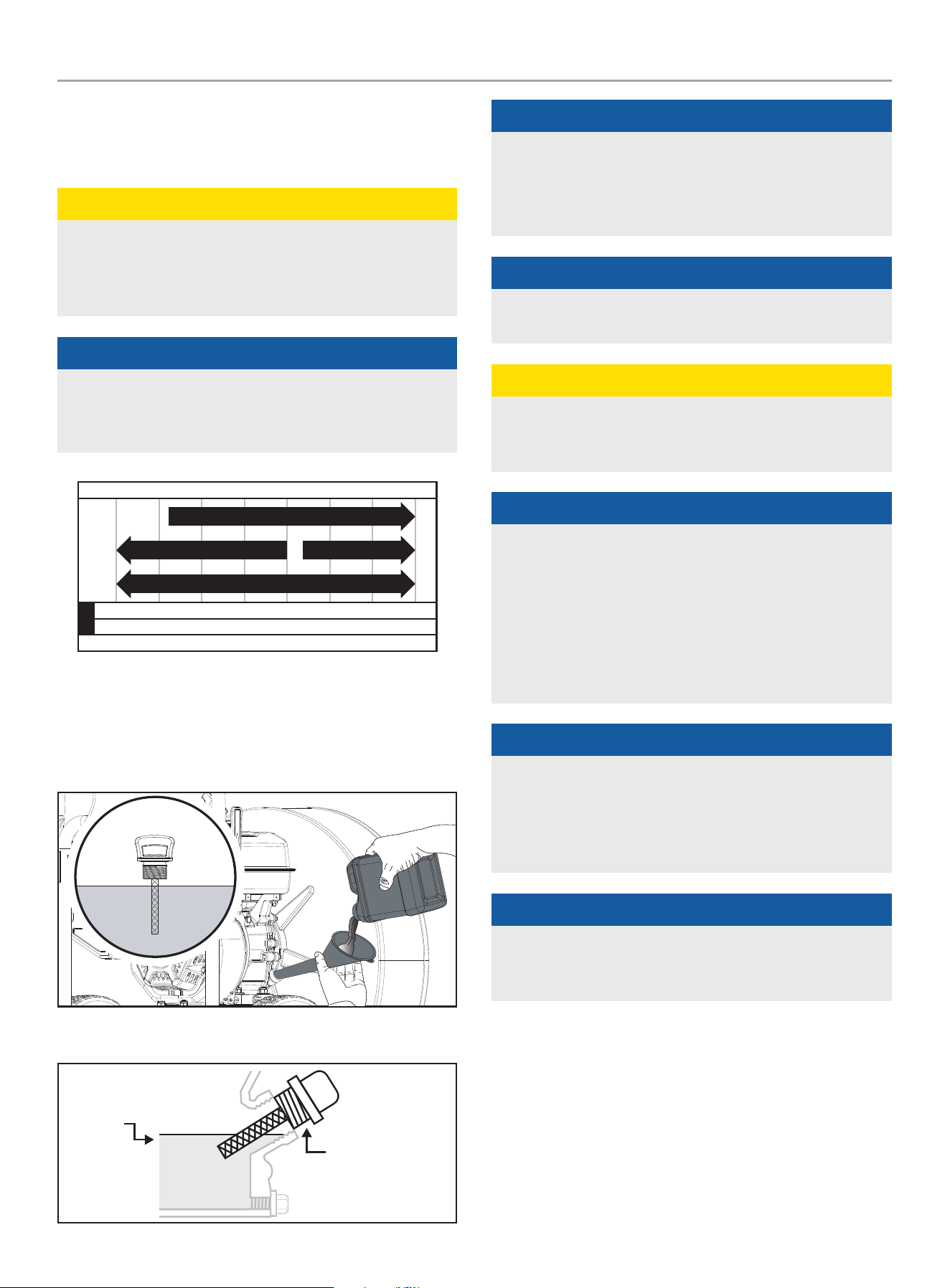
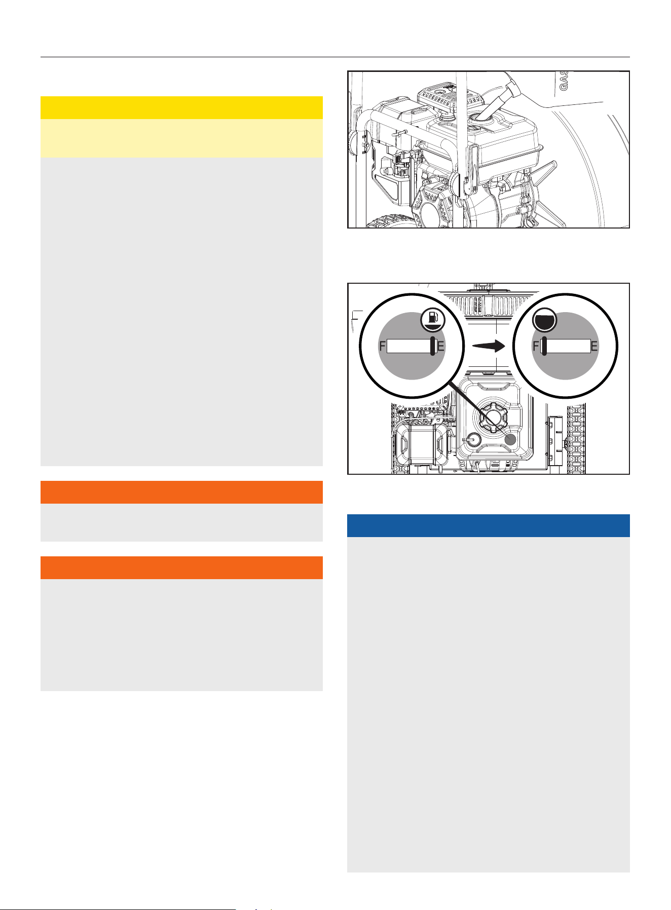
Add Engine Oil
CAUTiON
DO NOT attempt to crank or start the engine before it has been
properly filled with the recommended type and amount of oil.
Damage to the engine as a result of failure to follow these
instructions will void your warranty.
NOTiCE
The recommended oil type is 10W-30 automotive oil.
If running engine in extreme temperatures, refer to the
following chart for recommended oil type.
-20 0 20 40 60
Ambient temperature
Recommended Engine Oil Type
80 100 120
-28.9
°F
°C -17.8 -6.7 4.4 15.6 26.7 37.8 48.9
10W-30
5W-30 Full Synthetic
10W-405W-30
1. Place the blower on a flat, level surface.
2. Remove oil fill cap/dipstick to add oil.
3. Using a funnel, add up to 16.9 fl. oz (500 ml) of oil (included)
and replace oil fill cap/dipstick. DO NOT OVERFILL.
4. Check engine oil level before every use and add as needed.
MAX
OIL DIP STICK
NOTiCE
Once oil has been added, a visual check should show oil about
1-2 threads from running out of the fill hole.
If using the dipstick to check oil level, DO NOT screw in the
dipstick while checking.
NOTiCE
Check oil often during the break-in period. Refer to the
Maintenance section for recommended service intervals.
CAUTiON
The engine is equipped with a low oil shut-off and will stop
when the oil level in the crankcase falls below the threshold
level.
NOTiCE
The first 5 hours of run time is the break-in period for the
engine. During the break in period, it is recommended to use
standard automotive, non-synthetic blended oils. After the
break-in period synthetic oil, can be used but is not required.
Adjusting throttle setting will increase/ decrease engine speed
helping to seat piston rings. Avoid bogging or lugging the
engine down and avoid prolonged running at constant RPM.
After the 5 hour break-in period, change the oil.
NOTiCE
Synthetic oil may be used after the 5 hour initial break-
in period. Using synthetic oil does not decrease the
recommended oil change interval. Full synthetic 5W-30 oil
will aid in starting the engine in cold ambient < 41º F (5º C)
temperatures.
NOTiCE
Weather will affect engine oil and engine performance. Change
the type of engine oil used based on weather conditions to suit
the engine needs.
16
200947 - WALk BEhiND BLOWER
OPERATiON
Add fuel
CAUTiON
Use regular unleaded gasoline with a minimum octane rating
of 85 and an ethanol content of less than 10% by volume.
DO NOT light or smoke cigarettes.
DO NOT mix oil and gasoline.
DO NOT overfill the tank. Fill tank to approximately ¼ in.
(6.4 mm) below the top of the tank to allow for gasoline
expansion.
Always turn the blower off and let cool for minimum of two
minutes before removing the gasoline cap.
Afterwards, loosen gasoline cap to relieve pressure from the
gasoline tank.
Only fill or drain gasoline outdoors in a well-ventilated area.
Store fuel in a container approved for gasoline.
DO NOT pump gasoline directly into the blower at the gas
station. Always use an approved fuel container to transfer the
fuel to the gasoline tank.
DO NOT overfill the gasoline tank.
Always keep gasoline away from sparks, open flames, pilot
lights, heat and other sources of ignition.
WARNiNG
Pouring gasoline too fast through the fuel screen may result in
blow back of gasoline at the operator while filling.
WARNiNG
Always shut off engine before fueling. Never add fuel to a
machine with a running or hot engine. Wait at least 2 minutes
to allow for cool down before refueling. Move at least 50’
(15 m) from refueling site before starting engine. Do no smoke
and stay away from open flames and sparks. Failure to safely
handle fuel could result in serious personal injury and or
property damage.
1. Use clean, fresh, regular unleaded gasoline with a minimum
octane rating of 87 and an ethanol content of less than 10%
by volume. ybc
2. DO NOT mix oil with gasoline.
3. Remove the gasoline cap.
4. Slowly add gasoline to the tank. DO NOT OVERFILL. Gasoline
can expand after filling. A minimum of ¼ in. (6.4 mm) of
space left in the tank is required for gasoline expansion,
although more than ¼ in. (6.4 mm) is recommended. Gasoline
can be forced out of the tank as a result of expansion if
overfilled, and can affect the stable running condition of the
blower.
5. The approximate fuel level is shown on the fuel gauge on top
of the fuel tank.
6. Screw on the gasoline cap and wipe away any spilled fuel.
NOTiCE
Our engines work well with 10% or less ethanol blend
gasoline. When using ethanol-gasoline blends there are some
issues worth noting:
– Ethanol-gasoline blends can absorb more water than
gasoline alone.
– These blends can eventually separate, leaving water or a
watery goo in the tank, fuel valve and carburetor.
– The compromised gasoline can be drawn into the
carburetor and cause damage to the engine and/or create
power performance problems.
– There are only a few suppliers of fuel stabilizer that are
formulated to work with ethanol blend fuels.
– Any damages or hazards caused by using improper fuel,
improperly stored fuel, and/or improperly formulated
stabilizers, are not covered by manufacturer’s warranty.
It is advisable to always shut off the fuel supply (where
applicable - not every unit has a fuel shut off), run the
engine to fuel starvation and drain the tank when the
equipment is not in use for more than a 30-day period.
– See Storage instructions for extended non-use.
17
200947 - WALk BEhiND BLOWER
OPERATiON
DANGER
The blower engine exhaust contains carbon monoxide,
a colorless, odorless, poison gas. Breathing carbon monoxide
will cause nausea, dizziness, fainting or death.
If you start to feel dizzy or weak, get to fresh air immediately.
Operate the blower outdoors only in a well ventilated area.
DO NOT operate the blower inside any building, including
garages, basements, crawlspaces and sheds, enclosure or
compartment.
DO NOT allow exhaust fumes to enter a confined area through
windows, doors, vents or other openings.
DANGER
Using an engine indoors CaN KILL YOU IN mINUTES. Engine
exhaust contains carbon monoxide. This is a poison you cannot
see or smell.
NEVER use inside a home or garage, EVEN IF doors and
windows are open.
ONLY use OUTSIDE and far away from windows, doors,
and vents.
Install battery-operated carbon monoxide alarms or plug-in
carbon monoxide alarms with battery back-up according to the
manufacturer’s instructions.
WARNiNG
Running engines produce heat. Severe burns can occur on
contact. Combustible material can catch fire on contact.
DO NOT touch hot surfaces.
Avoid contact with hot exhaust gases.
Allow equipment to cool before touching.
Maintain at least 3 ft. (91.4 cm) of clearance on all sides to
ensure adequate cooling.
Maintain at least 5 ft. (1.5 m) of clearance from combustible
materials.
WARNiNG
Never run the unit without the blower fan cover installed.
Use of an improperly assembled unit could result in serious
personal injury.
NOTiCE
In some State and local jurisdictions, operate power equipment
during reasonable hours to comply with local noise ordinances.
For more information, contact your State and local government
for specific requirements.
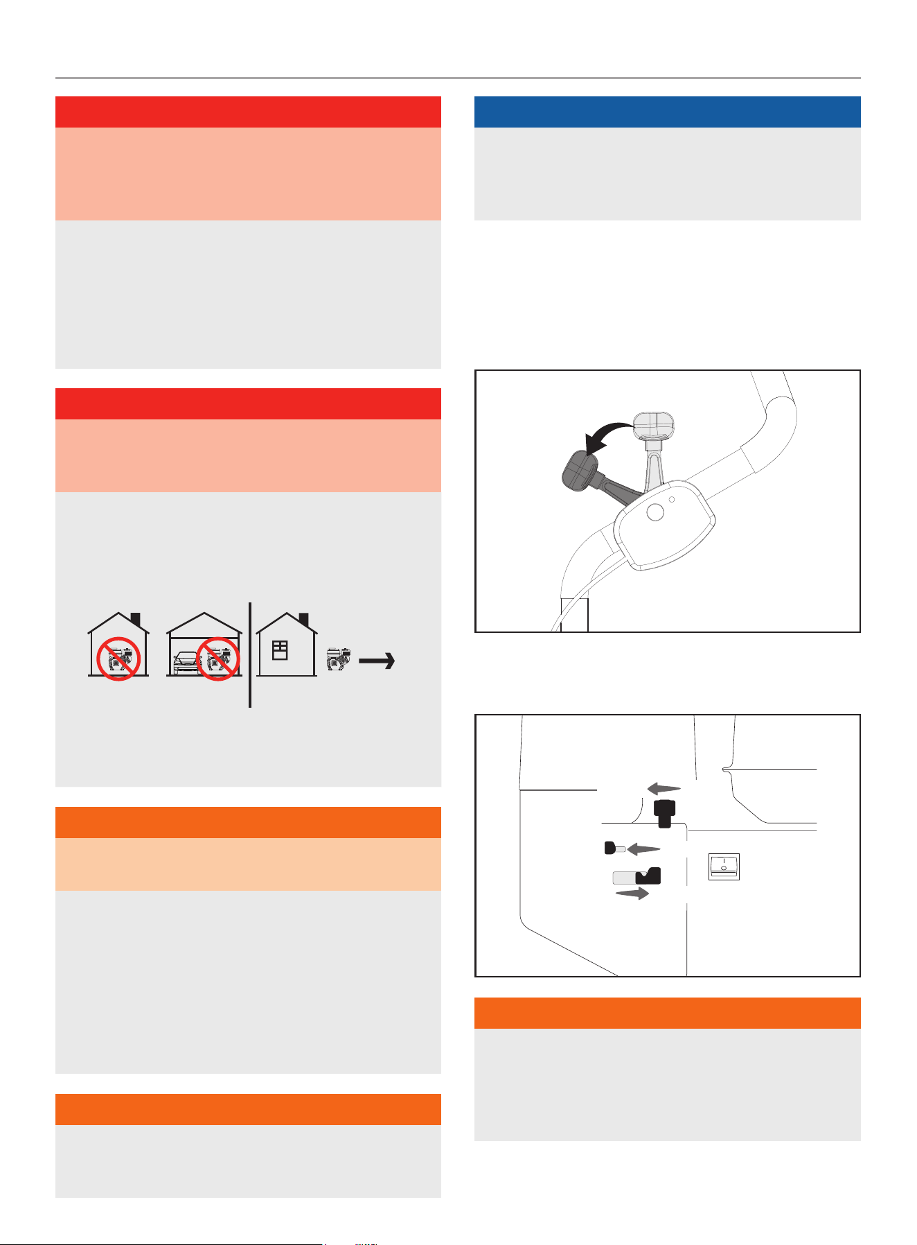
Starting the Engine
1. Make certain the blower is on a flat, level surface.
2. Move the throttle lever on the handle to the “FAST” position
(forward).
3. Move the choke lever to the “CHOKE” position.
4. Move the fuel valve to the “OPEN” position.
FUEL OFF FUEL ON
CHOKE RUN
FAST SLOW
WARNiNG
Rapid retraction of the recoil cord could pull your hand
and arm towards the engine faster than you can let go.
Unintentional startup can result in entanglement, traumatic
amputation or laceration. Broken bones, fractures, bruises or
sprains could also result.
18
200947 - WALk BEhiND BLOWER
OPERATiON
5. Pull the starter cord slowly until resistance is felt and then
pull rapidly.
6. As engine warms up, move the choke lever to the “RUN”
position.
CHOKE RUN
NOTiCE
Keep choke lever in “CHOKE” position for 2 pulls of the recoil
starter. After second pull, move choke lever to the “RUN”
position for up to the next 3 pulls of the recoil starter. Too
much choke leads to spark plug fouling/engine flooding due to
the lack of incoming air. This will cause the engine not to start.
NOTiCE
Allow engine to warm at least 30 seconds depending on
ambient temperature. The colder the temperature, the longer
the warm-up required.
Stopping the Engine
In an emergency, turn the engine switch to the “OFF”
position.
NOTiCE
If the engine does not stop when the engine switch is moved
to the “STOP” position, move the throttle to the slow speed
position and slide the choke lever to the cold start (closed)
position.
Under normal operation:
1. Turn the fuel valve to the “OFF” position.
2. Let the engine run until fuel starvation has stopped the
engine. This usually takes few minutes.
Important: Always ensure that the fuel valve is in the “OFF”
position when the engine is not in use.
NOTiCE
If the engine will not be used for a period of two (2) weeks or
longer, please see the Storage section for proper engine and
fuel storage.
19
200947 - WALk BEhiND BLOWER
OPERATiON
Blower Operation
WARNiNG
Always wear eye protection with side shields marked to
comply with ANSI Z87.1. Failure to do so could result in
objects being thrown into your eyes and other possible serious
injuries.
Before Each Use inspect the Blower
1. Always make sure the spark plug wire has been disconnected
and engine has been grounded.
2. Always visually inspect the blower fan cover for loose fittings,
cracks, or other damage.
3. DO NOT operate the blower if there is any indication of
damage to parts or the unit.
4. DO NOT operate the blower if the discharge chute is clogged.
Remove all debris before operation.
5. Always inspect the engine and make sure the oil level and
fuel level are correct before operating.
6. Always inspect the work area for any distractions or factors
that may prevent operator safety or proper operation.
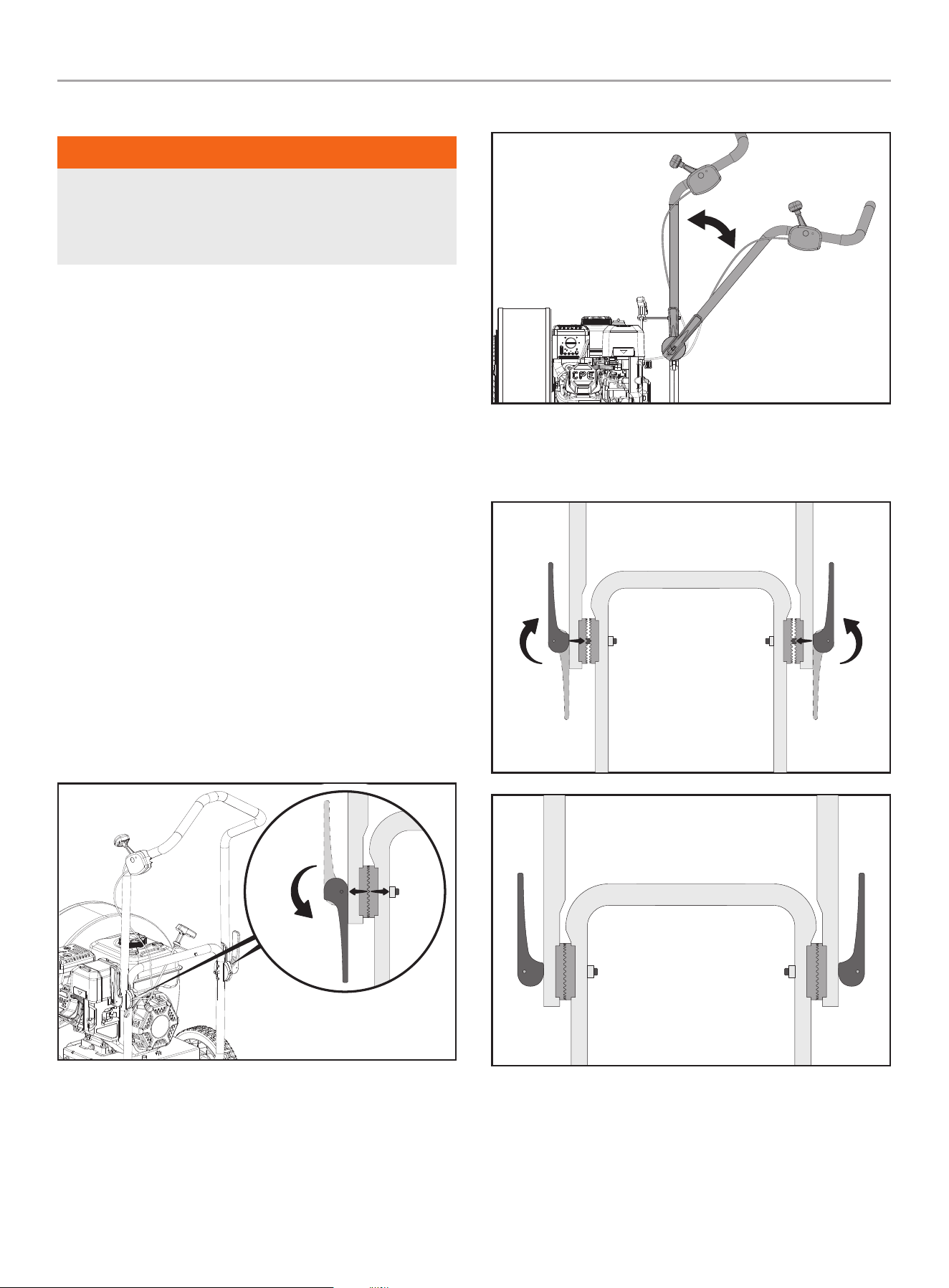
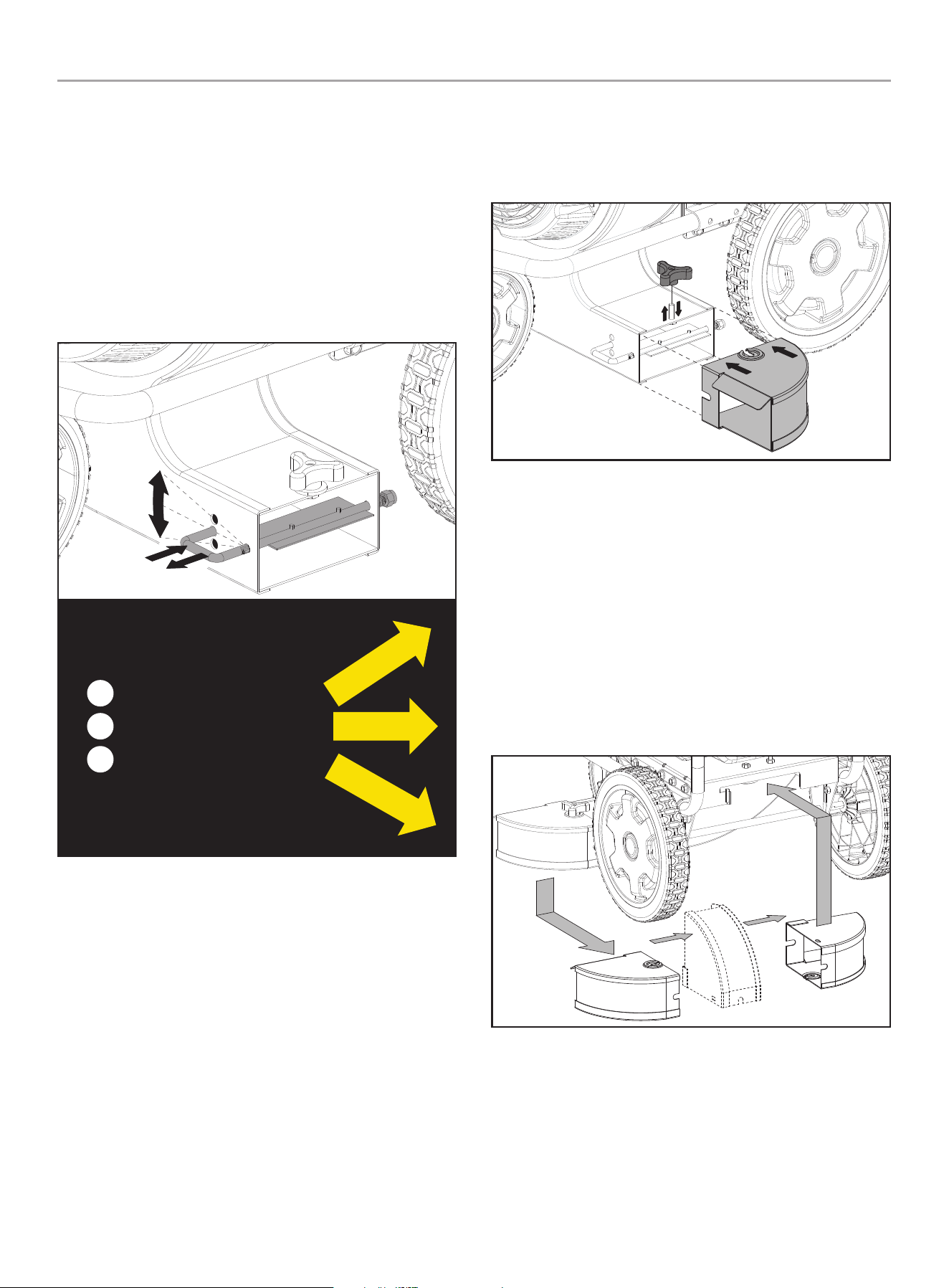
Adjust the handle height
The handle height can be adjusted to a comfortable position for
the user and, also be folded down for storage.
1. Pull the handle adjust lever outward to loosen the teeth
engagement on the adjusters.
2. Move the handle to the desired height for user comfort.
3. Ensure that the adjuster teeth are aligned to seat into each
other then, push the handle adjust lever inward to lock back
into place
20
200947 - WALk BEhiND BLOWER
OPERATiON
Vertical Air flow Adjustment
The blower is equipped with an adjustable vertical air flow louver.
The vertical air flow can be adjusted to 3 positions: Straight
(level), 15 degrees up and 15 degrees down.
1. Stop the engine (see Stopping the Engine section)
2. Pull the index lever out of its existing hole.
3. Rotate the index lever to the desired position.
4. Release the index lever and allow it to insert into the desired
hole.
15° DOWN
STRAIGHT/LEVEL
15° UP
5. To direct the air flow down 15 degrees, place the index lever
into the top position. To direct the air flow level/straight,
place the index lever into the middle position. To direct the
air flow up 15 degrees, place the index lever into the bottom
position.
forward Air flow Attachment
The blower includes a forward air flow attachment. Assembly of
this attachment to the discharge chute will direct the air flow to
the front of the blower instead of the side.
1. Stop the engine (see Stopping the Engine section).
2. Loosen the attachment knob located on top of the blower
discharge chute.
3. Orient the attachment so “This Side Up for Use” is visible and
the arrows are oriented toward the discharge chute.
4. Slide the attachment over the discharge chute. The slot
on the top of the attachment will mate with the bolt of the
attachment knob.
5. Hand-tighten the attachment knob to secure the attachment.
When not in use, the forward air flow attachment can be stored
under the frame at the rear of the blower.
1. Turn the attachment so “This Side Up for Storage” is visible
and the arrows are oriented towards the storage area.
2. Insert the attachment into frame opening, with the orientation
identified on the label.
3. The edge of the attachment will be supported by a bracket
under the frame.
4. Secure the attachment by forcing it upward and rotating
it so the pin on the frame will insert into the slot on the
attachment.
21
200947 - WALk BEhiND BLOWER
MAiNTENANCE
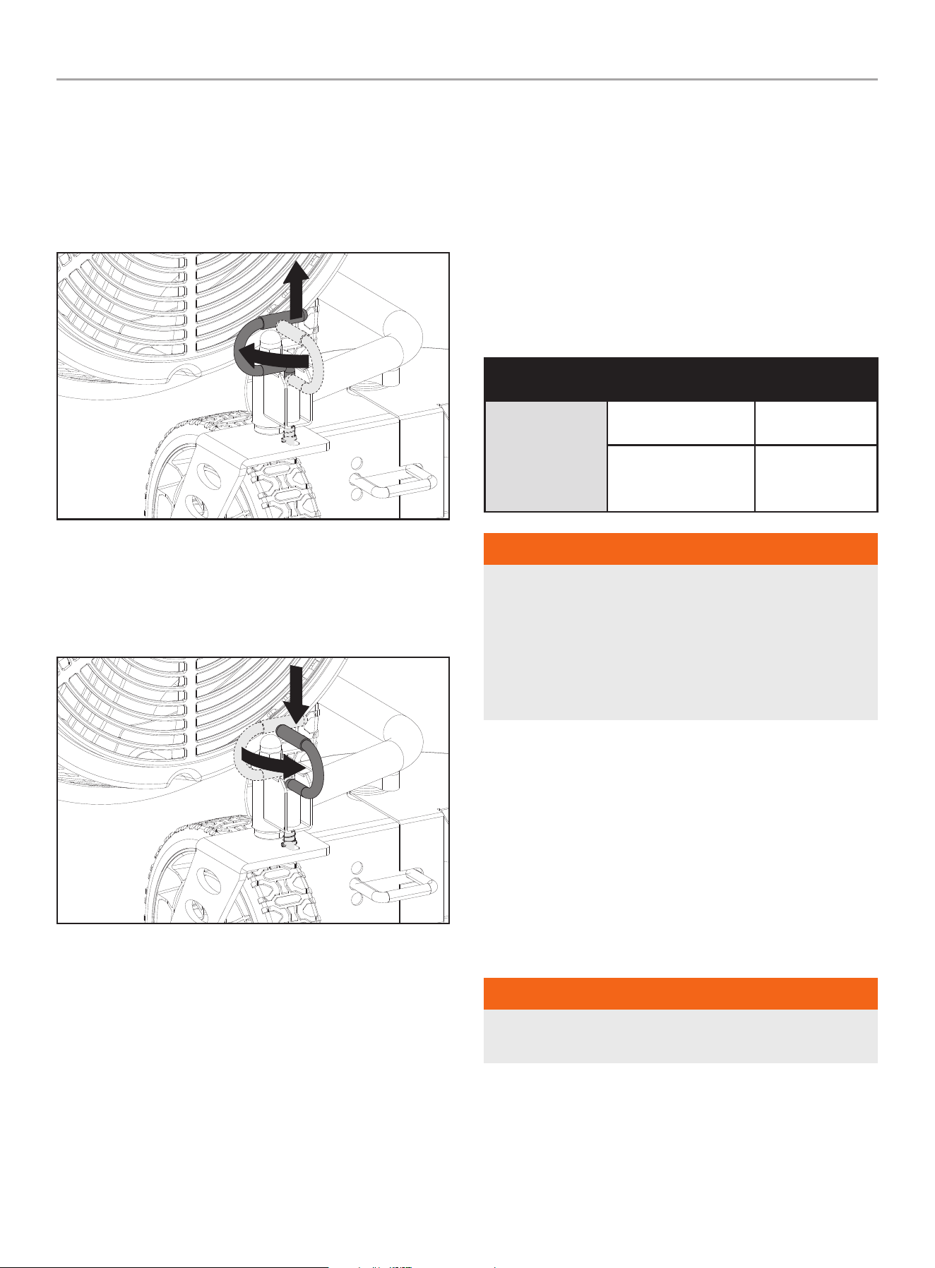
front Wheel Swivel
This blower has a multi-function front wheel that can be locked in
the front facing position or unlocked to swivel.
1. Pull up on the swivel lock lever and turn it a quarter turn to
lock into the slot in the up position. This will allow the wheel
to swivel 360 degrees.
2. To put the wheel back into the locked forward-facing position,
pull up on the swivel lock lever and turn it back a quarter of
a turn and let it seat back into the down position with the pin
locking into the hole on the wheel bracket. The wheel is now
locked into the front facing position.
Operation at high Altitude
The density of air at high altitudes is lower than at sea level.
Engine power is reduced as the air mass and air-fuel ratio
decrease. Engine power and output will be reduced approximately
3½% for every 1000 ft. of elevation above sea level. At high
altitudes increased exhaust emissions can also result due to the
increased enrichment of the air fuel ratio. Other high-altitude
issues can include hard starting, increased fuel consumption and
spark plug fouling.
To alleviate high altitude issues other than the natural power
loss, CPE can provide a high-altitude carburetor main jet. The
alternative main jet and installation instructions can be obtained
by contacting our Technical Support Team. Installation instructions
are also available in the Technical Bulletin area of the CPE website.
The part number and recommended minimum altitude for the
application of the high-altitude carburetor main jet is listed in the
following table.
In order to select the correct high-altitude main jet, it is necessary
to identify the carburetor model. For this purpose, a code is
stamped on the side of the carburetor.
Select the correct high-altitude jet part number corresponding to
the carburetor code found on your particular carburetor.
Carb. Code
high alt. Jet Part
Number
min. altitude
16100-Z2M0311-
00M0
16161-Z151710-00A1
3,000~6,000 ft.
(914.4~1,828.8 m)
16161-Z151510-00A1
6,000~8,000 ft.
(914.4~2438.4m)
WARNiNG
Operation using the alternative main jet at elevations lower
than the recommended minimum altitude can damage the
engine. For operation at lower elevations, the originally
supplied standard main jet must be used. Operating the
engine with the wrong engine configuration at a given altitude
may increase its emissions and decrease fuel efficiency and
performance.
MAiNTENANCE
Make certain that the blower is kept clean and stored properly.
Only operate the unit on a flat, level surface in a clean, dry
operating environment. DO NOT expose the unit to extreme
conditions, excessive dust, dirt, moisture or corrosive vapors.
The owner/operator is responsible for all periodic maintenance.
Complete all scheduled maintenance in a timely manner. Correct
any issue before operating the blower. For service or parts
assistance, contact our help line at 1-877-338-0999.
WARNiNG
Never operate a damaged or defective blower. Improper
maintenance will void your warranty.

22
200947 - WALk BEhiND BLOWER
MAiNTENANCE
WARNiNG
Before inspecting, cleaning, or servicing the blower, shut off
the engine. Wait for all moving parts to stop, disconnect spark
plug wire and move it away from the spark plug. Failure to
follow these instructions could result in personal injury or
damage to the blower.
NOTiCE
For emission control devices and systems, read and
understand your responsibilities for service as stated in the
Emission Control Warranty Statement of this manual.
WARNiNG
When servicing, use only genuine approved replacement parts.
Use of any other parts could result in poor performance or
damage the blower.
Cleaning the Blower
CAUTiON
DO NOT spray engine with water.
Water can contaminate the fuel system and can enter the
engine through the cooling slots and damage the engine.
1. Use a damp cloth to clean exterior surfaces of the blower.
2. Use a soft bristle brush to remove dirt and oil.
3. Use an air compressor (25 PSI) to clear dirt and debris from
the blower.
4. Inspect all air vents and cooling slots to ensure that they are
clean and unobstructed.
Engine Oil Services
Check the engine oil level before each use and after every five
hours of continuous operation. Running the engine when it is low
on oil will quickly ruin the engine. It is recommended that you
change the engine oil after every 10 hours of operation and even
sooner when operating in extremely dirty or dusty conditions.
a. Check the Engine Oil Level
1. Park the blower on a level area and shut off the engine.
2. Clean around the oil dipstick to prevent dirt from falling into
the crankcase.
3. Remove the dipstick and wipe it clean. Reinsert the dipstick
(do not tighten) and remove it. Add oil as needed to bring the
level up to the FULL mark. Wipe the dipstick clean each time
the oil level is checked. Do not overfill.
4. Tighten dipstick securely.
MAX
OIL DIP STICK
B. Changing the Engine Oil
CAUTiON
DO NOT attempt to crank or start the engine before it has been
properly filled with the recommended type and amount of oil.
Damage to the blower as a result of failure to follow these
instructions will void your warranty.
NOTiCE
The recommended oil type is 10W-30 automotive oil.
Change oil when the engine is warm. Refer to the oil specification
to select the proper grade for your operating environment.
1. Place the blower on a flat, level surface.
2. Clean around the oil drain plug to prevent dirt from falling into
the crankcase. Remove oil drain plug with a 10mm socket
(not included)
DRAIN BOLT
23
200947 - WALk BEhiND BLOWER
MAiNTENANCE
3. Allow the oil to drain completely into an appropriate container.
4. Replace the oil drain plug.
5. Remove the oil fill cap/dipstick to add oil.
6. Add oil according to Add Engine Oil in Assembly section.
7. DO NOT OVERFILL. Oil not included for routine maintenance.
8. Dispose of used oil at an approved waste management
facility.
NOTiCE
Once oil has been added, a visual check should show oil about
1-2 threads from running out of the fill hole. When using the
dipstick to check oil level, DO NOT screw in the dipstick while
checking.
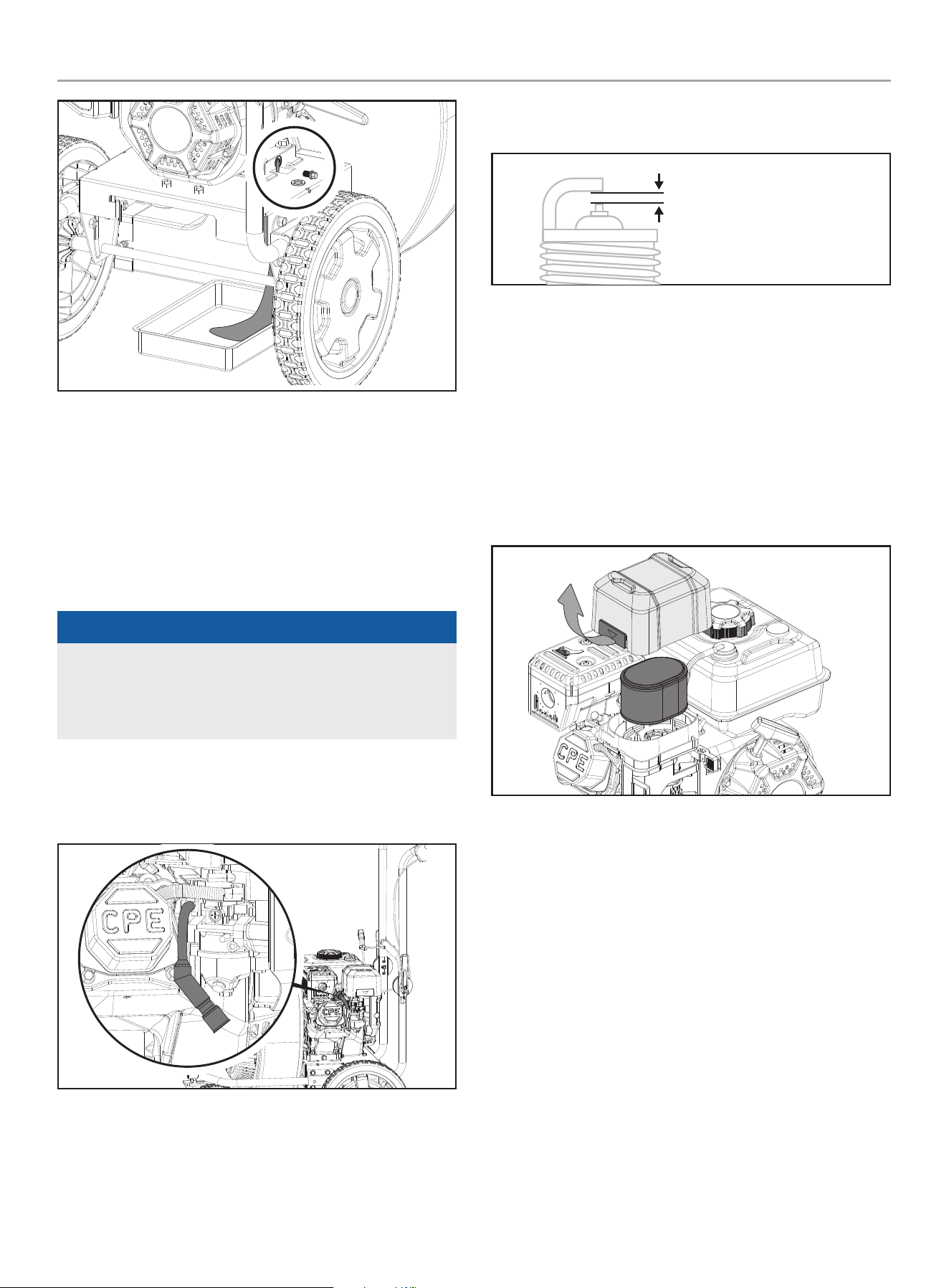
Cleaning and Adjusting the Spark Plug(s)
1. Remove the spark plug cable from the spark plug.
2. Use a spark plug socket tool (not included), or a 13/16 in.
(21 mm) socket (not included) to remove the plug.
3. Inspect the electrode on the plug. It must be clean and not
worn to produce the spark required for ignition.
4. Make certain the spark plug gap is 0.028-0.031 in.
(0.7-0.8 mm).
SPARK PLUG GAP
5. Refer to the spark plug types in Specifications when replacing
the plug.
6. Firmly re-install the plug.
7. Attach the spark plug cable to the spark plug.
Cleaning the Air filter
1. Using your finger, pry the outer tab up slightly and lift the air
filter cover above the tab lock position.
2. Remove both air filter cover and air filter element.
3. Wash in liquid detergent and water. Squeeze thoroughly dry in
a clean cloth.
4. Saturate in clean engine oil.
5. Squeeze in a clean, absorbent cloth to remove all excess oil.
6. Place the filter in the assembly.
7. Reattach the air filter cover. Attach the side closest to the
gas tank then pivot down to close. Make sure air filter cover
snaps in place.
Cleaning the Spark Arrestor
1. If so equipped, allow the engine to cool completely before
servicing the spark arrester.
2. Remove the screws holding the cover plate which retains the
end of the spark arrester to the muffler.
3. Remove the spark arrester screen.

24
200947 - WALk BEhiND BLOWER
STORAGE
4. Carefully remove the carbon deposits from the spark arrester
screen with a wire brush.
5. Replace the spark arrester if it is damaged.
6. Position the spark arrestor on the muffler and attach with the
screws removed in step 2.
CAUTiON
Failure to clean the spark arrestor will result in degraded
engine performance.
NOTiCE
Federal and local laws and administrative requirements
indicate when and where spark arrestors are required. When
ordered, spark arrestors are required for operation of this
blower in National Forest lands. In California, this blower must
not be used on any forest-covered land, brush-covered land, or
grass-covered land unless the engine is equipped with a spark
arrestor.
WARNiNG
Always check for fuel leaks before use. A leaking fuel cap is
a hazard and must be replaced immediately. If any leaks are
found, correct the problem before using the product. Failure
to do so could result in a fire hazard that could cause serious
personal injury, including equipment and property damage.
Adjusting the Governor
NOTiCE
Tampering or adjusting the factory set carburetor is a Federal
Violation and will void your warranty coverage.
The air-fuel mixture is not adjustable. Tampering with the governor
can damage your blower and will void your warranty. Contact our
Technical Support Team at 1-877-338-0999 for all other service
and/or adjustment needs.
Maintenance Schedule
Follow the service intervals indicated in the following maintenance
schedule.
Service your blower more frequently when operating in adverse
conditions.
Contact our Technical Support Team at 1-877-338-0999 to locate
the nearest CPE certified service dealer for your blower or engine
maintenance needs.
EVERY 8 hOURS OR DaILY
Check oil level
Clean around air intake and muffler
FIRST 5 hOURS
Change oil
EVERY 50 hOURS OR EVERY SEaSON
Clean air filter
Change oil if operating under heavy load or in hot
environments
EVERY 100 hOURS OR EVERY SEaSON
Change oil
Clean/adjust spark plug
Check/adjust valve clearance*
Clean spark arrestor
Clean fuel tank and filter*
EVERY 250 hOURS
Clean combustion chamber*
EVERY 3 YEaRS
Replace fuel line*
* To be performed by knowledgeable, experienced owners or Champion Power
Equipment certified dealers.
STORAGE
Refer to the Maintenance section for proper cleaning instructions.
1. Allow the blower to cool completely before storage.
2. Turn off the fuel supply at the fuel valve.
3. Clean the blower according to the instructions in the
Maintenance section.
4. Store the unit in a clean, dry area out of direct sunlight.
Short Term Engine Storage (Up to 30 Days)
1. Allow the engine to cool completely before storage.
2. Clean engine according to the Maintenance section.

25
200947 - WALk BEhiND BLOWER
STORAGE
3. To extend the fuel storage life add a properly formulated fuel
stabilizer to the tank.
4. Ensure the fuel valve is in the “OFF” position.
Long Term Engine Storage (30 Days – 1 Year)
1. Add a properly formulated fuel stabilizer to the tank.
2. Run the engine for a few minutes so the treated fuel cycles
through the fuel system and carburetor.
3. Turn the fuel valve to the “OFF” position.
4. Let the engine run until fuel starvation has stopped the
engine. This usually takes a few minutes.
5. The engine needs to cool completely before cleaning and
storage.
6. Clean the engine according to the Maintenance section.
7. Change the oil according to the Maintenance section.
8. Remove the spark plug and pour about 1/2 oz. (14.9 mL) of oil
into the cylinder. Crank the engine slowly to distribute the oil
and lubricate the cylinder.
9. Reattach the spark plug.
WARNiNG
Never store the blower indoors or next to appliances where
there is a source of heat, open flame, spark or pilot light as
these conditions can ignite gasoline vapors. DO NOT store the
blower near fertilizer or any corrosive material. Even with an
empty fuel tank, gasoline vapors could ignite. When storing the
blower for short or long periods of time, always be sure that
the engine switch (where applicable) and the fuel valve (where
applicable) are set in the “OFF” position.
NOTiCE
The engine works well with 10% or less ethanol blend fuels.
When using blended fuels, there are some issues worth noting:
– Ethanol-gasoline blends can absorb more water than
gasoline alone.
– These blends can eventually separate, leaving water or a
watery goo in the tank, fuel valve and carburetor.
– The compromised gasoline can be drawn into the
carburetor and cause damage to the engine and/or create
power performance problems.
– There are only a few suppliers of fuel stabilizer that are
formulated to work with ethanol blend fuels.
– Any damages or hazards caused by using improper fuel,
improperly stored fuel, and/or improperly formulated
stabilizers, are not covered by manufacturer’s warranty.
It is advisable to always shut off the fuel supply (where
applicable - not every unit has a fuel shut off), run the
engine to fuel starvation and drain the tank when the
equipment is not in use for more than a 30-day period.
NOTiCE
To avoid possible damage to the threads, do not try to remove
the plug from a hot aluminum cylinder head.

26
200947 - WALk BEhiND BLOWER
SPECifiCATiONS
SPECifiCATiONS
Blower Specifications
Model ....................................................... 200947
Air Velocity* ...........................Max 160 MPH (257.5 km/h)
...............................................Max 1300 CFM (ft
3
/min)
Sound Pressure ........................... 85 dB(A) @ 20 ft. (6 m)
Wheel Diameter ..... 12 in. (30.5 cm) Rear / 8 in. (20.3 cm) Front
* Rated per ANSI/OPEI B175.2
Overall Dimensions
Net Weight ........................................... 104 lb. (47 kg)
Length ............................................35.9 in. (91.2 cm)
Width .............................................. 26.8 in. (68 cm)
Height ........................................... 47.4 in. (120.5 cm)
Engine Specifications
Model ........................................................ R224P
Displacement (cc) ...............................................224
Type ................................................... 4-Stroke OHV
Start Type .................................................... Recoil
Spark Plug Specifications
OEM .................................................... NHSP F6RTC
Replacement ...........................NGK BPR6ES or equivalent
Gap (in/mm) ..............................0.028 - 0.031 / 0.7 - 0.8
Valve Specifications
Intake Clearance (in/mm) ............ 0.0039 - 0.0059 / 0.1 - 0.15
Exhaust Clearance (in/mm) ..........0.0059 - 0.0079 / 0.15 - 0.2
NOTiCE
A technical bulletin regarding valve adjustment procedures is
available at www.championpowerequipment.com.
Oil Specifications
NOTiCE
Temperature will affect engine oil and engine performance.
Change the type of engine oil used based on temperature
shown in the “Recommended Engine Oil Type” table.
-20 0 20 40 60
Ambient temperature
Recommended Engine Oil Type
80 100 120
-28.9
°F
°C -17.8 -6.7 4.4 15.6 26.7 37.8 48.9
10W-30
5W-30 Full Synthetic
10W-405W-30
Oil Capacity (fl. oz/mL) ...................................16.9 / 500
fuel Specifications
Use regular unleaded gasoline with a minimum octane rating of 87
and an ethanol content of less than 10% by volume. DO NOT USE
E15 or E85. DO NOT OVERFILL.
Fuel Capacity (gal/L) .......................................0.82/3.1
important Message About Temperature
NOTiCE
An important message about temperature: Your product
is designed and rated for continuous operation at ambient
temperatures up to 104°F (40°C). When needed, it may be
operated at temperatures ranging from 5°F (-15°C) to 122°F
(50°C) for short periods of time. If exposed to temperatures
outside this range during storage, it should be brought back
within this range before operation. In any event, the product
must always be operated outdoors, in a well-ventilated are and
away from doors, windows and vents.
Starting Temperature Range (°F/°C) ........... 5 to 104/-15 to 40
27
200947 - WALk BEhiND BLOWER
SPECifiCATiONS
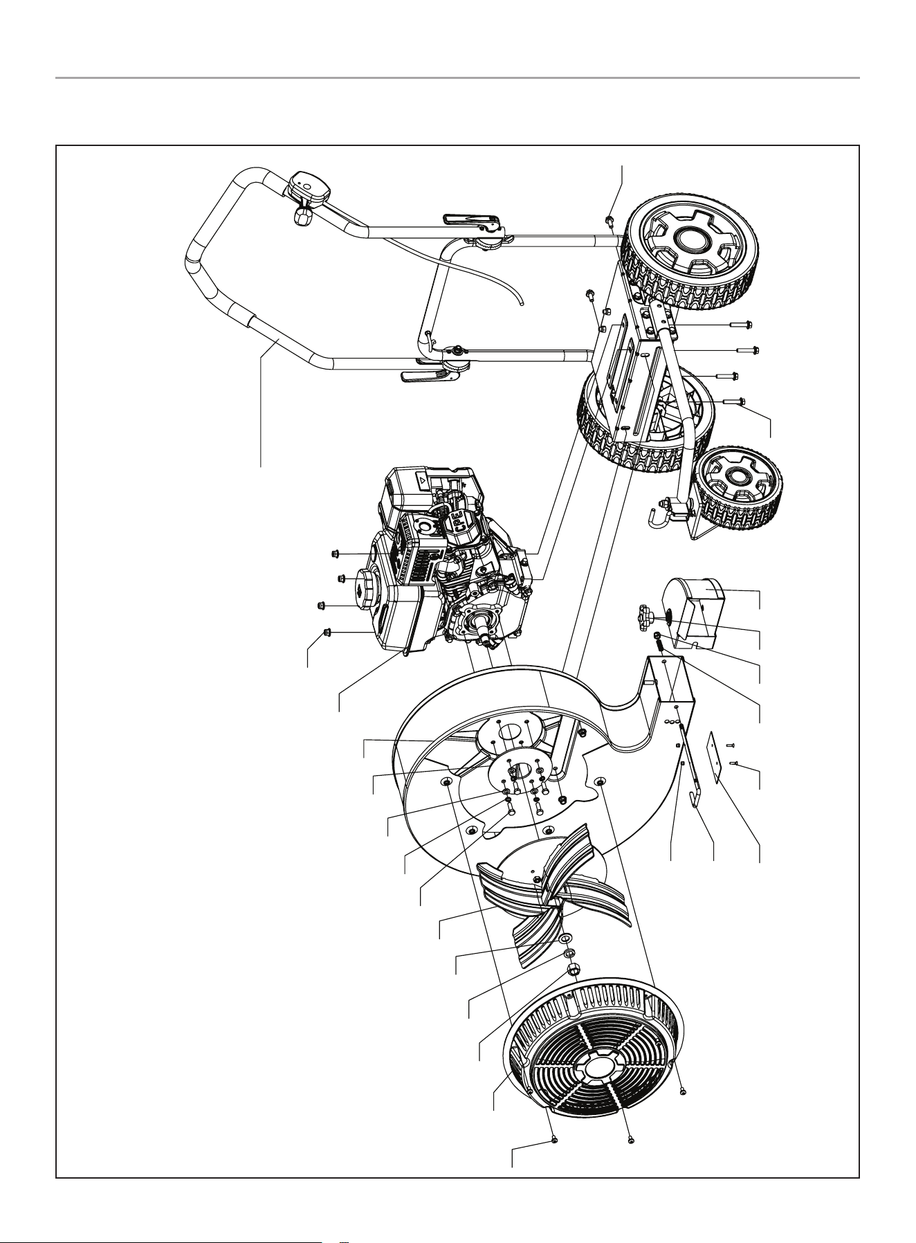
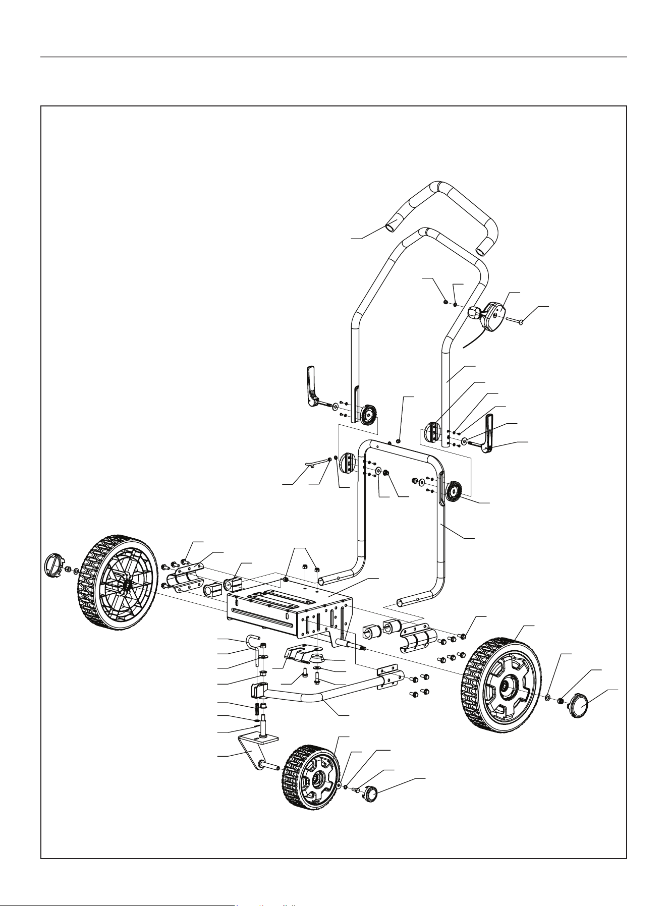
Parts Diagram - figure A
Figure A
1
2
3
7
11
5
6
4
8
1615
14
17
18 22 19 20
21
23
12
13
See Figure B
9
10
28
200947 - WALk BEhiND BLOWER
SPECifiCATiONS
# Part Number Description Qty.
1 2550011234 Hex Bolt M6×12 6
2 2540006536 Fan Guard 1
3
2550011227
S/N:<202008001944
Bolt
5/16×25-24UNF-12.9
1
2550011732
S/N:>202011001669+
Nut GB6171 M16×1.5
4 2550000883 Spring Washer Ø8 11
5
2570000811
S/N:<202008001944
Impeller Assembly 1
2570000821
S/N:>202011001669+
6 2550011344
Bolt
5/16×25-24UNF-8.8
4
7
2560004102
S/N:<202008001944
Bushing
1
2550011734
S/N:>202011001669+
Spring Washer Ø16
8 2550011239 Flat Washer Ø8 4
9 2540006548 Subplate 1
10 2540006535 Volute Assembly 1
11
2550011339
S/N:<202008001944
Flat Key 4.78 x 35
1
2550011733
S/N:>202011001669+
Flat Washer Ø16
12
2560004098
S/N:<202008001944
Gasoline Engine
R224P-B00KY
1
2560004155
S/N:>202011001669+
# Part Number Description Qty.
13 2550001556 Nut GB6177.1 M8 6
14 2540006537
Wind-direction
Adjusting Bracket
1
15 2540006538 Wind-direction Plate 1
16 2550011247 Bolts M4 x 16 2
17 2550011235 Locknut M4 2
18 2560004099 Compression Spring 1 1
19 2540006558 Locking Lever 1
20 2540006539 Outlet Assembly 1
21 2550011599
Hexagon Bolt
M8 x 40-8.8
4
22 2550011476 Locknut M8 1
23 2550011242
Hexagon Bolt
M8 x 20-8.8
2
Parts List - figure A
29
200947 - WALk BEhiND BLOWER
SPECifiCATiONS
Parts Diagram - figure B
1
24
2
3
4
5
6
7
8
9
10
1
20
15
2
9
22
23
25
26
27
32
13
14
35
17
16
21
33
34
36
9
31
23
9
19
18
11
12
28
30
9
31
23
29
27
37
Figure B
38
39

30
200947 - WALk BEhiND BLOWER
SPECifiCATiONS
# Part Number Description Qty.
1 2550011243 Locknut M6 2
2 2550002033 Flat Washer Ø6 3
3 2540006550
Throttle Control
Assembly
1
4 2550011246 Bolts GB12 M6 x 65 1
5 2540006560 Handlebar 1
6 2540006551
Upper Handlebar
Connecting Base
2
7 2550000963 Flat Washer Ø4 8
8 2550011388
Cross-head Tapping
Screw
8
9 2550011244 Large Flat Washer Ø8 8
10 2570000813
Handle Height Adjust
Lever
2
11 2540006555
Lower Handlebar
Connecting Base
2
12 2540006549 Lower Handlebar 1
13 2550011236 Locknut M10 3
14 2550011245 Flat Washer Ø10 1
15 2550001551 Nut GB6170 M6 1
16 2540006563 Flange Bushing 2
17 2560004100
Compression Spring
Ø2
1
18
2540006557
S/N: <202011003180
Rear Wheel Assembly,
12in. Yellow
2
71224016-03700
S/N: NP2105160001+
19 2550001554 Locknut M8 2
20 2550011417 Starter Rope Bracket 1
21 2550011239 Gasket Ø8 1
22 2550011238 Nut GB6183.1 M8 2
23 2550004645
Hexagon Bolt
M8 x 20-8.8
17
24 2540006559 Handle Grip 1
25 2540006562 Handlebar Bracket 2
26 2540006556 Rubber Bushing 4
27 2550001556 Nut GB6177.1 M8 14
28
2540006545
S/N: <202011003180
Base Assembly 1
71224016-03300
S/N: NP2105160001+
Parts List - figure B
# Part Number Description Qty.
29 2540006546 Nozzle Bracket 1
30 2540006547 Rubber Sleeve 1
31 2550011242 Hex bolt M8 x 20 2
32 2540006544
Front Wheel Hinge Pin
Assembly
1
33 2550011603 Cotter Pin Ø2.5×16 1
34
2540006543
S/N: <202011003180
Front Wheel Swivel
Mount
1
71224016-03400
S/N: NP2105160001+
35 2540006542
Front Wheel
Connecting Mount
1
36
2550011636
S/N: <202011003180
Front Wheel Assembly,
8in. Yellow
1
71224016-03500
S/N: NP2105160001+
37
None
S/N: <202011003180
None /
GB/T 93-87 8
S/N: NP2105160001+
Spring Washer Ø8 1
38 71224016-03014
Cover, Wheel Hub,
12 in. Yellow
2
39 71224016-03011
Cover, Wheel Hub, 8 in.
Yellow
1
31
200947 - WALk BEhiND BLOWER
SPECifiCATiONS
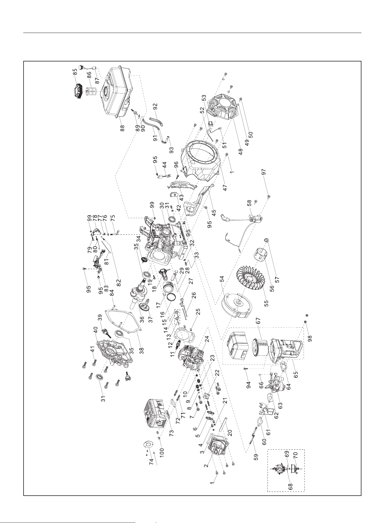
Engine Parts Diagram
46

32
200947 - WALk BEhiND BLOWER
SPECifiCATiONS
Engine Parts List
# Part Number Description Qty.
1 90001-0612-0101
Hexagon Flange Bolt,
M6 x 12,
Blue White Zinc
8
2 12410-Z440110-0001
Cylinder Head Cover
Subassembly,
Blue White Zinc
1
3 12004-Z440110-00A0
Cylinder Head Cover
Gasket
1
4 14314-Z010110-00A0 Valve Adjusting Nut 2
5 14311-Z010110-00A0 Valve Rocker 2
6 14313-Z010110-00A0 Valve Adjusting Bolt 2
7 12003-Z010110-0001
Cylinder Head Bolt,
M8 x 60,
Blue White Zinc
4
8 12109-Z810110-00A0 Valve Lock Clamp 4
9 12103-Z010110-0000 Valve Spring 2
10 12101-Z810210-00A0 Seal Guide 1
11 30010-Z010110-00A0 Spark Plug, F6RTC 1
12 12131-Z950210-0000 Cylinder Head Gasket 1
13 12121-Z810120-00A0 Exhaust Valve 1
14 12111-Z810110-00A0 Inlet Valve 1
15 12110-Z810120-00A9 Valve Set 1
16 13200-Z140210-00A9 Piston Ring Assembly 1
17 13122-Z510210-00A0 Piston Pin Clip 2
18 13010-Z810210-00A0
Connecting Rod
Assembly
1
19 90001-0630-0101
Hexagon Flange Bolt,
M6 x 30,
Blue White Zinc
1
20 17004-Z440110-0002
Tube, Breather,
Ø8 x Ø12 x 90
1
21 14312-Z010110-00A0 Valve Lock Nut 2
22 14090-Z010110-0000
Lifter Stopper Plate
Subassembly,
Blue White Zinc
1
23 12112-Z810210-00A0 Valve Spring Retainer 2
24 12140-Z810210-00A0
Cylinder Head
Subassembly
1
25 90502-1114-00A0 Pin, 11 x 14 2
26 14071-Z440110-00A0 Valve Lifter 2
27 14081-Z040110-00A0 Valve Tappet 2
28 13111-Z810120-00A0 Piston 1
29 13121-Z810110-00A0
Piston Pin,
Ø13 x Ø45.9
1
30 11310-Z810310-0000
Crankcase
Subassembly
1
# Part Number Description Qty.
31 90682-Z300110-0001
Oil Seal,
Ø25 x Ø41.25 x 6
2
32 90408-Z010110-00A0
Washer,
Ø10 x Ø15.8 x 1.5
2
33 11007-Z010110-0001
Drain Plug Bolt,
M10 x1.25 x15,
Blue White Zinc
2
34 16400-Z810210-00A0
Governor Gear
Assembly
1
35 90547-0205-00 Bearing 2
36 13300-Z812310-00A0 Crankshaft Assembly 1
37 14200-Z810310-0000 Camshaft Assembly 1
38 11001-Z440110-00A0 Crankcase Gasket 1
39 15010-Z290110-L401
Oil Dipstick
Subassembly
2
40 11411-Z440410-00A0 Crankcase Cover 1
41 90001-0832-0101
Hexagon Flange Bolt,
M8 x 32,
Blue White Zinc
6
42 90684-Z010510-0000 Clip Ø20 x 43 1
43 19340-Z011011-0000 Lower Shield 1
44 37050-Z010210-0001
Oil Protector, Blue
White Zinc
1
45 19304-Z010610-0001
Cylinder Body Shroud,
Blue White Zinc
1
46 90107-4285-01A0 Screw 3
47 28110-Z810410-L400 Shroud 1
48 28200-Z141010-H200
Recoil Starter
Assembly
1
49 90408-0600-03 Washer Ø6, Black Zinc 3
50 90001-0608-03
Hexagon Flange Bolt,
M6 x 8, Black Zinc
3
51 35541-Z010610-0000
Stop Engine
Connecting Wire
1
52 35555-Z810110-0000
Switch Connector
Grounding Wire
1
53 35540-Z010610-R901
Stop Engine Switch
Subassembly
1
54 13510-Z440810-00A0 Flywheel Subassembly 1
55 19352-Z440110-0001 Impeller 1
56 28002-Z0L0110-0000
Starter Pulley, Blue
White Zinc
1
57 13501-Z010110-00A0
Flywheel Nut,
M14 x 1.5,
Blue White Zinc
1
58 30400-Z2M0110-0000 Ignition Coil 1

33
200947 - WALk BEhiND BLOWER
SPECifiCATiONS
# Part Number Description Qty.
59 90204-Z620110-00A0
Stud, M6 x 115,
Black Zinc
2
60 16002-Z010110-0000
Carburetor Insulator
Gasket
1
61 16003-Z010110-00A0
Carburetor Insulator
Plate
1
62 16001-Z010110-0000 Carburetor Gasket 1
63 16100-Z2M0311-00M0 Carburetor Assembly 1
64 17001-Z010210-0000 Air Cleaner Gasket 1
65 17100-Z012210-00A1 Air Cleaner Assembly 1
66 90722-Z2R0110-0000 End Plug 1
67 17150-Z2M0110-0000 Air Cleaner Element 1
68 16112-Z010110-0000 Seal Ring, Float 1
69
16161-Z151910-00A1 Main Jet, Standard 1
16161-Z151710-00A1
Main Jet, Altitude
3000-6000 Feet
/
16161-Z151510-00A1
Main Jet, Altitude
6000-8000 Feet
/
70 90681-Z010610-0000 Seal Ring 1
71 90203-Z010110-0000
Stud, M8 x 34,
Black Zinc
2
72 18001-Z440110-00A0 Exhaust Gasket 1
73 18100-Z140710-00A0 Muffler Assembly 1
74 18250-Z2M0110 -0000 Spark Arrestor 1
75 16061-Z010110-00A0 Governor Arm 1
76 90408-Z010210-00A0
Washer,
Ø6.2 x Ø15 x 0.6
1
77 90501-Z010110-0001 Pin, Blue White Zinc 1
78 16070-Z010110-0101
Governor Support
Subassembly,
Blue White Zinc
1
79 16072-Z010110-0001
Governor Support Bolt,
M6 x 21,
Blue White Zinc
1
80 16063-Z810210-0000 Spring, Governor 1
81 16062-Z010110-0001
Governeor Rod, Blue
White Zinc
1
82 16012-Z010310-00A0
Throttle Valve
Returning Spring
1
83 16520-Z012610-0100
Throttle Control
Assembly
1
84 90502-0912-00A0 Pin, 9 x 12 2
85 16730-Z440810-LK01 Fuel Tank Cap 1
86 16652-Z010810-0001 Fuel Strainer 1
87 37200-Z810210-0001 Fuel Gauge 1
88 16620-Z810310-H200 Fuel Tank, 3.1L 1
# Part Number Description Qty.
89 16680-Z010210-0000
Fuel Tank Oil Outlet
Subassembly
1
90 90740-Z010510-00A1 Clamp 1
91 90686-Z010710-00M1
Fuel Pipe,
Ø4.5 x Ø8.5 x 160
1
92 30431-Z010110-0003
Rubber Jacket,
Ø9.5 x Ø11 x 90, Black
1
93 90685-D080-0EA0 Clamp, Ø8 x 7 x 0.6 1
94 90007-0630-A1A0
Hexagon Flange Bolt,
M6 x 30,
Blue White Zinc
1
95 90001-0610-01A1
Hexagon Flange Bolt,
M6 x 10,
Blue White Zinc
5
96 90001-0616-01A0
Hexagon Flange Bolt,
M6 x 16,
Blue White Zinc
1
97 90001-0625-01A0
Hexagon Flange Bolt,
M6 x 25,
Blue White Zinc
2
98 90305-0600-33
Hexagon Flange Nut,
M6, Black Zinc
2
99 90305-0600-3101
Hexagon Flange Nut,
M6, Blue White Zinc
3
100 90303-0800-3101
Hexagon Nut, M8,
Blue White Zinc
2

34
200947 - WALk BEhiND BLOWER
TROUBLEShOOTiNG
TROUBLEShOOTiNG
Problem Cause Solution
Engine does not start
Spark plug wire disconnected. Reconnect wire.
Engine Throttle Control Lever incorrectly
set.
Put lever in START position.
Fuel tank empty. Add fuel.
Choke control (if so equipped) in incorrect
position.
Move to CHOKE position.
Stale gasoline. Drain fuel and add fresh fuel.
Dirty air filter Clean or replace filter
Defective or incorrectly gapped spark plug Inspect spark plug
Carburetor out of adjustment Contact Technical Support Team
Misadjusted throttle control Contact Technical Support Team
Dirt or water in fuel tank Contact Technical Support Team
Engine Runs Poorly
Defective or incorrectly gapped spark plug Inspect the spark plug
Dirty air filter Clean or replace filter
Carburetor out of adjustment Contact Technical Support Team
Stale gasoline. Replace with fresh gasoline
Dirt or water in fuel tank Contact Technical Support Team
Engine cooling system clogged Clean air-cooling system
Engine Overheats
Engine cooling system clogged Clean air-cooling system
Carburetor out of adjustment Contact Technical Support Team
Oil level is low Check oil level
Excessive vibration/noise
Loose parts Check and tighten all fasteners
See engine problems above See engine solutions above
Engine does not shut off
Misadjusted throttle control or ignition
switch
Contact Technical Support Team
Air flow is low
Throttle is in slow position Ensure throttle is in fast position
Air intake is clogged Clean any debris from the air intake
Air discharge is clogged Clear any obstructions from the discharge
For further technical support:
Technical Support Team
Mon-Fri 8:30 AM-5:00 PM (PST/PDT)
Toll Free 1-877-338-0999
support@championpowerequipment.com

WARRANTY*
CHAMPION POWER EQUIPMENT
2 YEAR LIMITED WARRANTY
Warranty Qualifications
To register your product for warranty and FREE lifetime call center
technical support please visit:
https://www.championpowerequipment.com/register
To complete registration you will need to include a copy of the
purchase receipt as proof of original purchase. Proof of purchase
is required for warranty service. Please register within ten (10)
days from date of purchase.
Repair/Replacement Warranty
CPE warrants to the original purchaser that the mechanical and
electrical components will be free of defects in material and
workmanship for a period of two years (parts and labor) from
the original date of purchase and 180 days (parts and labor) for
commercial and industrial use. Transportation charges on product
submitted for repair or replacement under this warranty are the
sole responsibility of the purchaser. This warranty only applies to
the original purchaser and is not transferable.
Do Not Return The Unit To The Place Of
Purchase
Contact CPE’s Technical Service and CPE will troubleshoot any
issue via phone or e-mail. If the problem is not corrected by
this method, CPE will, at its option, authorize evaluation, repair
or replacement of the defective part or component at a CPE
Service Center. CPE will provide you with a case number for
warranty service. Please keep it for future reference. Repairs or
replacements without prior authorization, or at an unauthorized
repair facility, will not be covered by this warranty.
Warranty Exclusions
This warranty does not cover the following:
Normal Wear
Products with mechanical and electrical components need
periodic parts and service to perform well. This warranty does not
cover repair when normal use has exhausted the life of a part or
the equipment as a whole.
Installation, Use and Maintenance
This warranty will not apply to parts and/or labor if the product is
deemed to have been misused, neglected, involved in an accident,
abused, loaded beyond the product’s limits or modified. Normal
maintenance is not covered by this warranty and is not required to
be performed at a facility or by a person authorized by CPE.
Other Exclusions
This warranty excludes:
– Cosmetic defects such as paint, decals, etc.
– Wear items such as starter pulleys, starter ropes, filter
elements, belts, blower fans, impeller blades, blower and/or
vacuum tubes, vacuum bag and straps (where applicable), etc.
– Failures due to acts of God and other force majeure events
beyond the manufacturer’s control.
– Problems caused by parts that are not original Champion
Power Equipment parts.
Limits of Implied Warranty and
Consequential Damage
Champion Power Equipment disclaims any obligation to cover
any loss of time, use of this product, freight, or any incidental
or consequential claim by anyone from using this product.
THIS WARRANTY AND THE ATTACHED U.S. EPA and/or CARB
EMISSION CONTROL SYSTEM WARRANTIES (WHEN APPLICABLE)
ARE IN LIEU OF ALL OTHER WARRANTIES, EXPRESS OR IMPLIED,
INCLUDING WARRANTIES OF MERCHANTABILITY OR FITNESS
FOR A PARTICULAR PURPOSE.
A unit provided as an exchange will be subject to the warranty
of the original unit. The length of the warranty governing the
exchanged unit will remain calculated by reference to the purchase
date of the original unit.
This warranty gives you certain legal rights which may change
from state to state or province to province. Your state or province
may also have other rights you may be entitled to that are not
listed within this warranty.
Contact Information
Address
Champion Power Equipment, Inc.
12039 Smith Ave.
Santa Fe Springs, CA 90670 USA
www.championpowerequipment.com
Customer Service
Toll Free: 1-877-338-0999
info@championpowerequipment.com
Fax no.: 1-562-236-9429
Technical Service
Toll Free: 1-877-338-0999
tech@championpowerequipment.com
EMERGENCY 24 HOUR SUPPORT: 1-562-204-1188
*Except as otherwise stipulated in any of the following enclosed Emission Control System Warranties (when applicable) for the Emission Control System: U.S. Environment Protection Agency
(EPA) and/or California Air Resources Board (CARB).

CHAMPION POWER EQUIPMENT, INC. (CPE),
THE UNITED STATES ENVIRONMENTAL PROTECTION AGENCY (U.S. EPA)
AND THE CALIFORNIA AIR RESOURCES BOARD (CARB) EMISSION CONTROL SYSTEM WARRANTY
Your Champion Power Equipment (CPE) engine complies with both the U.S. EPA and state of California Air Resources Board
(CARB) emissions regulations.
YOUR WARRANTY RIGHTS AND OBLIGATIONS:
The US EPA, California Air Resources Board, and CPE are pleased to explain the Federal and California Emission Control Systems warranty
on your 2021 small off-road engine (SORE) and equipment. In the United States and California, new small off-road engines (SORE) and new
equipment that use small off-road engines (SORE) must be designed, built and equipped to meet the State’s stringent anti-smog standards.
CPE must warrant the emission control system on your small off-road engine (SORE) and equipment for the period of time listed below,
provided there has been no abuse, neglect or improper maintenance of your small off-road engine (SORE) and equipment leading to the
failure of the emission control system.
Your emission control system may include parts such as the carburetor, fuel-injection system, the ignition system, catalytic converter, fuel
tanks, fuel lines (for liquid fuel and fuel vapors), fuel caps, valves, canisters, filters, clamps, connectors, and other associated components.
Also included may be hoses, belts, and other emission related assemblies. Where a warrantable condition exits, CPE will repair your small
off-road engine (SORE) and equipment at no cost to you including diagnosis, parts and labor.
MANUFACTURER’S WARRANTY COVERAGE:
This Emissions Control System is warranted for two years. If any emissions-related part on your small off-road engine (SORE) and
equipment is defective, the part will be repaired or replaced by CPE.
OWNER WARRANTY RESPONSIBILITIES:
As the small off-road engine (SORE) and equipment owner, you are responsible for the performance of the required maintenance listed
in your Owner’s Manual. CPE recommends that you retain all your receipts covering maintenance on your small off-road engine (SORE)
and equipment, but CPE cannot deny warranty coverage solely for the lack of receipts or for your failure to ensure the performance of all
scheduled maintenance.
As the small off-road engine (SORE) and equipment owner, you should be aware that CPE may deny you warranty coverage if your small
off-road engine (SORE) and equipment or a part has failed due to abuse, neglect, improper maintenance or unapproved modifications.
You are responsible for presenting your small off-road engine (SORE) and equipment to an Authorized CPE service outlet or alternate
service outlet as described in (3)(f.) below, CPE dealer or CPE, Santa Fe Springs, Ca. as soon as a problem exists. The warranty repairs
shall be completed in a reasonable amount of time, not to exceed 30 days.
If you have any questions regarding your warranty coverage, you should contact:
Champion Power Equipment, Inc.
Customer Service
12039 Smith Ave.
Santa Fe Springs, CA 90670
1-877-338-0999
tech@championpowerequipment.com

EMISSION CONTROL SYSTEM WARRANTY
The following are specific provisions relative to your Emission Control System (ECS) Warranty Coverage.
1. APPLICABILITY: This warranty shall apply to 1995 and later model year California small off-road engines (SORE) (for other states,
1997 and later model year engines). The ECS Warranty Period shall begin on the date the new engine or equipment is delivered to its
original, end-use purchaser, and shall continue for 24 consecutive months thereafter.
2. GENERAL EMISSIONS WARRANTY COVERAGE
CPE warrants to the original, end-use purchaser of the new engine or equipment and to each subsequent purchaser that each of its
small off-road engines (SORE) is:
2a. Designed, built and equipped so as to conform to U.S. EPA emissions standards for spark- ignited engines at or below 19 kilowatts
and all applicable regulations adopted by the California Air Resources Board; and
2b. Free from defects in materials and workmanship that cause the failure of a warranted part to be identical in all material respects
to the part as described in the engine manufacturer’s application for certification for a period of two years.
3. THE WARRANTY ON EMISSION-RELATED PARTS WILL BE INTERPRETED AS FOLLOWS:
3a. Any warranted part that is not scheduled for replacement as required maintenance in the Owner’s Manual shall be warranted for
the ECS Warranty Period. If any such part fails during the ECS Warranty Period, it shall be repaired or replaced by CPE according
to Subsection “d” below. Any such part repaired or replaced under the ECS Warranty shall be warranted for a time not less than
the remainder of the ECS Warranty Period.
3b. Any warranted, emissions-related part which is scheduled only for regular inspection as specified in the Owner’s Manual shall be
warranted for the ECS Warranty Period. A statement in such written instructions to the effect of “repair or replace as necessary”
shall advise owners of the warranty coverage for emission related parts. Replacement within the warranty period is covered by
the warranty and shall not reduce the ECS Warranty Period. Any such part repaired or replaced under the ECS Warranty shall be
warranted for a time not less than the remainder of the ECS Warranty Period.
3c. Any warranted, emissions-related part which is scheduled for replacement as required maintenance in the Owner’s Manual shall
be warranted for the period of time prior to the first scheduled replacement point for that part. If the part fails prior to the first
scheduled replacement, the part shall be repaired or replaced by CPE according to Subsection “d” below. Any such emissions-
related part repaired or replaced under the ECS Warranty, shall be warranted for a time not less than the remainder of the ECS
Warranty Period prior to the first scheduled replacement point for such emissions-related part.
3d. Repair or replacement of any warranted, emissions-related part under this ECS Warranty shall be performed at no charge to the
owner at a CPE Authorized Service Outlet.
3e. The owner shall not be charged for diagnostic labor which leads to the determination that a part covered by the ECS Warranty is in
fact defective, provided that such diagnostic work is performed at a CPE Authorized Service Outlet.
3f. CPE shall pay for covered emissions warranty repairs at non-authorized service outlets under the following circumstances:
i. The service is required in a population center with a population over 100,000 according to U.S. Census 2000 without a CPE
Authorized Service Outlet AND
ii. The service is required more than 100 miles from a CPE Authorized Service Outlet. The 100 mile limitation does not apply in the
following states: Alaska, Arizona, Colorado, Hawaii, Idaho, Montana, Nebraska, Nevada, New Mexico, Oregon, Texas, Utah and
Wyoming.
3g. CPE shall be liable for damages to other original engine components or approved modifications proximately caused by a failure
under warranty of an emission-related part covered by the ECS Warranty.
3h. Throughout the ECS Warranty Period, CPE must maintain a supply of warranted emission-related parts sufficient to meet the
expected demand for such emission-related parts and must obtain additional parts if that supply is exhausted.
3i. Any CPE Authorized and approved emission-related replacement part that do not increase the exhaust or evaporative emissions of
the engine or emissions control system may be used in the performance of any ECS Warranty maintenance or repair and will be
provided without charge to the owner. Such use shall not reduce CPE’s warranty obligation.
3j. Unapproved add-on or modified parts may not be used to modify or repair a CPE engine. Such use voids this ECS Warranty and
shall be sufficient grounds for disallowing an ECS Warranty claim. CPE shall not be liable hereunder for failures of any warranted
parts of a CPE engine caused by the use of such an unapproved add-on or modified part.

EMISSION-RELATED PARTS INCLUDE THE FOLLOWING: (using those portions of the list applicable to the
engine)
Systems covered by this
warranty
Parts Description
Fuel Metering System Fuel regulator, Carburetor and internal parts
Air Induction System Air cleaner, Intake manifold
Ignition System Spark plug and parts, Magneto ignition system
Exhaust System Exhaust manifold, catalytic converter
Miscellaneous Parts Tubing, Fittings, Seals, Gaskets, and Clamps associated with these listed systems.
Evaporative Emissions Fuel Tank, Fuel Cap, Fuel Lines (for liquid fuel and fuel vapors), Fuel Line Fittings, Clamps, Pressure
Relief Valves, Control Valves, Control Solenoids, Electronic Controls, Vacuum Control Diaphragms,
Control Cables, Control Linkages, Purge Valves, Gaskets, Liquid/Vapor Separator, Carbon Canister,
Canister Mounting Brackets, Carburetor Purge Port Connector
TO OBTAIN WARRANTY SERVICE:
You must take your CPE engine or the product on which it is installed, along with your warranty registration card or other proof of original
purchase date, at your expense, to any Champion Power Equipment dealer who is authorized by Champion Power Equipment, Inc. to
sell and service that CPE product during his normal business hours. Alternate service locations defined in Section (3)(f.) above must be
approved by CPE prior to service. Claims for repair or adjustment found to be caused solely by defects in material or workmanship will not
be denied because the engine was not properly maintained and used.
If you have any questions regarding your warranty rights and responsibilities, or to obtain warranty service, please write or call
Customer Service at Champion Power Equipment, Inc.
Champion Power Equipment, Inc.
12039 Smith Ave.
Santa Fe Springs, CA 90670
1-877-338-0999
Attn.: Customer Service
tech@championpowerequipment.com
