OPERATOR'S MANUAL
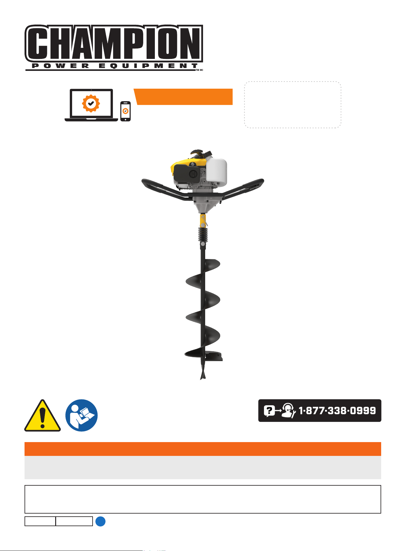
MODEL #201092
EARTh AUgER
Champion Power Equipment, Inc.
SAVE ThESE INSTRUCTIONS. This manual contains important safety precautions which should be read and understood before operating the product. Failure to do
so could result in serious injury. This manual should remain with the product.
Specifications, descriptions and illustrations in this manual are as accurate as known at the time of publication, but are subject to change without notice.
3966-M-OP REV 20240115
EN
or visit championpowerequipment.com
WARNINg
To reduce the risk of injury, the user must read and understand the operator’s manual before using this product. If you do not
understand the warnings and instructions in the operator’s manual, do not use this product.
ACTIVATE YOUR WARRANTY
by registering your product:
championpowere quipment.com
SERIAL NO.

201092 - EARTh AUgER
TAbLE Of CONTENTS
2
TAbLE Of CONTENTS
Introduction ................................................... 3
Safety Definitions ..........................................3
Important Safety Instructions .......................4
Fuel Safety ........................................................ 5
Safety and Dataplate Labels ...................................... 7
Safety Symbols .................................................... 8
Operation Symbols ............................................... 10
Quick Start Label Symbols....................................... 10
Controls and features ................................. 11
Earth Auger ....................................................... 11
Parts Included .................................................... 12
Tools Needed ..................................................... 12
Assembly ..................................................... 13
Unpacking ........................................................ 13
Assemble the Fishtail Point to the Auger Bit .................... 13
To Assemble Auger Bit to Powerhead ........................... 13
Add Engine Oil .................................................... 13
Operation ..................................................... 14
Fueling and Refueling ............................................ 14
Starting the Engine ............................................... 15
Stopping the Engine .............................................. 17
Operating the Auger .............................................. 17
Transporting the Auger .......................................... 18
Maintenance ................................................ 18
Cleaning the Earth auger ........................................ 18
Changing the Engine Oil ......................................... 19
Cleaning and Adjusting the Spark Plug(s) ....................... 19
Cleaning the Air Filter ............................................ 20
Earth Blade and Fishtail Point ................................... 20
Adjusting the Governor ........................................... 20
Maintenance Schedule ........................................... 21
Storage ........................................................21
When storing 1 month or shorter: ............................... 21
When storing longer than a month:.............................. 21
Specifications .............................................. 22
Earth Auger Specifications ...................................... 22
Engine Specifications ............................................22
Oil Specifications .................................................22
Fuel Specifications ...............................................22
Temperature Specifications ......................................22
Troubleshooting ........................................... 23
fOR PARTS bREAKDOWN
Search by model number at
championpowerequipment.com

201092 - EARTh AUgER
INTRODUCTION
3
SAfETY DEfINITIONS
The purpose of safety symbols is to attract your attention to
possible dangers. The safety symbols, and their explanations,
deserve your careful attention and understanding. The safety
warnings do not by themselves eliminate any danger. The
instructions or warnings they give are not substitutes for proper
accident prevention measures.
DANgER
DANGER indicates a hazardous situation which, if not avoided,
will result in death or serious injury.
WARNINg
WARNING indicates a hazardous situation which, if not
avoided, could result in death or serious injury.
CAUTION
CAUTION indicates a hazardous situation which, if not avoided,
could result in minor or moderate injury.
NOTICE
NOTICE indicates information considered important, but not
hazard-related (e.g., messages relating to property damage).
INTRODUCTION
Congratulations on your purchase of a Champion Power Equipment
(CPE) product. CPE designs, builds, and supports all of our
products to strict specifications and guidelines. With proper
product knowledge, safe use, and regular maintenance, this
product should bring years of satisfying service.
Every effort has been made to ensure the accuracy and
completeness of the information in this manual at the time of
publication, and we reserve the right to change, alter and/or
improve the product and this document at any time without prior
notice.
CPE highly values how our products are designed, manufactured,
operated, and serviced as well as providing safety to the operator
and those around the earth auger. Therefore, it is IMPORTANT to
review this product manual and other product materials thoroughly
and be fully aware and knowledgeable of the assembly, operation,
dangers and maintenance of the product before use. Fully
familiarize yourself, and make sure others who plan on operating
the product fully familiarize themselves too, with the proper safety
and operation procedures before each use. Please always exercise
common sense and always err on the side of caution when
operating the product to ensure no accident, property damage,
or injury occurs. We want you to continue to use and be satisfied
with your CPE product for years to come.
When contacting CPE about parts and/or service, you will need to
supply the complete model and serial numbers of your product.
Transcribe the information found on your product’s nameplate
label to the table below
CPE TECHNICAL SUPPORT TEAM
1-877-338-0999
MODEL NUMBER
201092
SERIAL NUMBER
DATE OF PURCHASE
PURCHASE LOCATION
201092 - EARTh AUgER
IMPORTANT SAfETY INSTRUCTIONS
4
IMPORTANT SAfETY INSTRUCTIONS
WARNINg
Cancer and Reproductive Harm – www.P65Warnings.ca.gov
DANgER
Earth auger exhaust contains carbon monoxide, a colorless,
odorless, poisonous gas. Breathing carbon monoxide will
cause nausea, dizziness, fainting or death. If you start to feel
dizzy or weak, get to fresh air immediately.
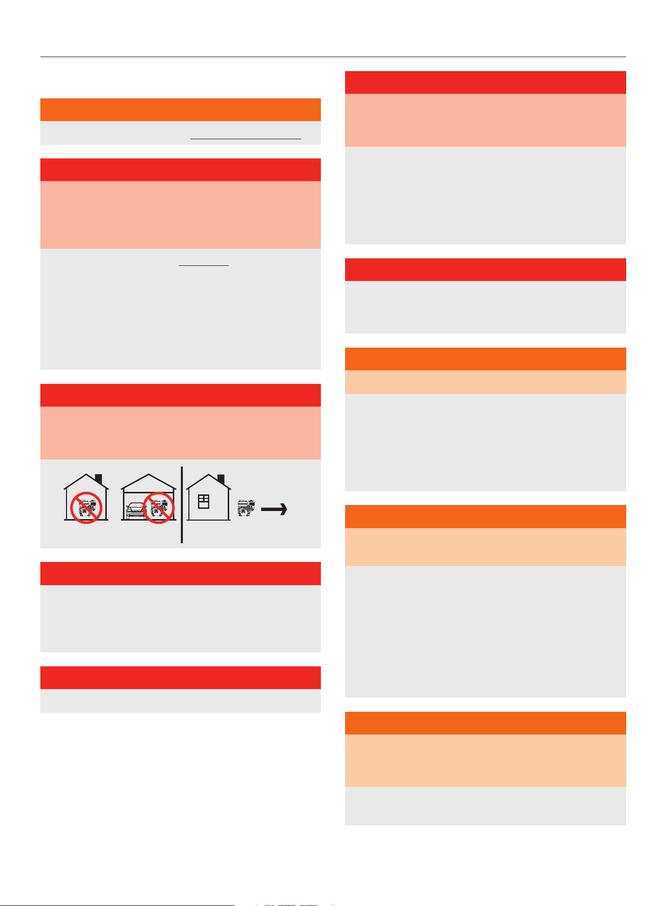
OPERATE THE EARTH AUGER OUTDOORS ONLY IN A WELL
VENTILATED AREA AND POINT EXHAUST AWAY.
NEVER operate the earth auger inside any building, including
garages, basements, sheds or other confined spaces.
DO NOT allow exhaust fumes to enter a confined area through
windows, doors, vents or other openings while operating the
auger.
DANgER
Using an engine indoors CAN KILL YOU IN MINUTES. Engine
exhaust contains carbon monoxide. This is a poison you cannot
see or smell.
DANgER
Contact your local utility company to locate underground
electrical lines or pipes prior to using this product. Failure to do
so may result in serious personal injury or death and possible
damage to equipment or property.
DANgER
DO NOT allow untrained individuals or children to use this unit.
DANgER
Rotating parts can entangle hands, feet, hair, clothing and/or
accessories. Traumatic amputation or severe laceration can
result.
Keep hands and feet away from rotating parts.
Tie up long hair and remove jewelry.
Operate equipment with guards in place.
DO NOT wear loose-fitting clothing, dangling drawstrings or
items that could become caught.
DANgER
Rotating blades can cause severe bodily injury. Stop the engine
and ensure blades have stopped rotating before installing/
changing parts or performing maintenance.
WARNINg
Sparks can result in fire or electrical shock.
When servicing the earth auger:
Disconnect the spark plug wire and place it where it cannot
contact the plug or any other metal object.
DO NOT check for spark with the plug removed.
Use only approved spark plug testers.
WARNINg
Running engines produce heat. Severe burns can occur on
contact. Combustible material can catch fire on contact.
DO NOT touch hot surfaces.
Avoid contact with hot exhaust gases.
Allow equipment to cool before touching.
Maintain at least 3 ft. (91.4 cm) of clearance on all sides to
ensure adequate cooling.
Maintain at least 5 ft. (1.5 m) of clearance from combustible
materials.
WARNINg
Rapid retraction of the recoil cord will pull hand and arm
towards the engine faster than you can let go. Broken bones,
fractures, bruises or sprains could result.
When starting engine, pull the recoil cord slowly until
resistance is felt and then pull rapidly to avoid kickback.

201092 - EARTh AUgER
IMPORTANT SAfETY INSTRUCTIONS
5
WARNINg
– Clear the work area before each use. Remove all objects
such as rocks, broken glass, nails, wire, or string which
can be thrown or become entangled in the machine.
– Always wear eye protection with side shields marked to
comply with ANSI Z87.1. Failure to do so could result in
objects being thrown into your eyes and other possible
serious injuries.
– Keep all bystanders, children, and pets at least 50’ (15m)
away when operating the earth auger.
– Always wear sound protection (ear mufflers or ear plugs) to
reduce the risk of hearing loss associated with long term
engine sound level(s).
– Always wear heavy long pants, boots, gloves, and a long-
sleeve shirt. Do not wear loose clothing, jewelry, short
pants, sandals, or go barefoot. Secure long hair so it is
above shoulder level to prevent entanglement in rotating
parts.
– Do not operate this unit when you are tired, ill, or under the
influence of alcohol, drugs, or medication.
– Do not operate in poor lighting.
– Always wear a face filter mask in dusty conditions to
reduce the risk of injury associated with the inhalation of
dust.
– Keep firm footing and balance. Maintain a firm grip on the
handle with both hands while using the auger.
– Do not overreach. Overreaching can result in loss of
balance or exposure to hot contact surfaces or rotating
parts.
– This engine is equipped with a spark arrestor. Never
operate the unit without a spark arrestor screen.
– Although the earth auger contains a spark arrester,
maintain a minimum distance of 5 ft. (1.5 m) from dry
vegetation to prevent fires.
– Always inspect the unit before each use for loose
fasteners, fuel leaks, etc. Replace damaged parts.
– Use only identical manufacturer’s replacement parts and
accessories. Use of any other replacement parts may
create a hazard or cause product damage and void your
warranty.
– Maintain the equipment per maintenance instructions
located in this Operator’s Manual
CAUTION
Prolonged exposure to vibrations, also known as vibration
white finger, through use of gasoline-powered equipment,
such as this auger, could cause blood vessel or nerve damage
in fingers, hands, and joints. If symptoms occur such as
numbness, or loss of feeling in the fingers, hands, or joints,
discontinue the use of this auger and seek medical attention.
fuel Safety
DANgER
GASOLINE AND GASOLINE VAPORS ARE HIGHLY
FLAMMABLE AND EXPLOSIVE.
Fire or explosion can cause severe burns or death.
Gasoline and gasoline vapors:
– Gasoline vapors are highly flammable and explosive.
– Gasoline vapors can cause a fire or explosion if ignited.
– Gasoline is a liquid fuel and the resulting gasoline vapors can
ignite and cause a fire or explosion.
– Gasoline is a skin irritant and needs to be cleaned up
immediately if spilled on skin or clothes.
– Gasoline has a distinctive odor, this will help detect potential
leaks quickly.
– In any petroleum gas fire, flames should not be extinguished
unless by doing so the fuel supply valve can be turned OFF.
This is because if a fire is extinguished and a supply of fuel is
not turned OFF, then an explosion hazard could be created.
– Gasoline vapors expand and contract with ambient
temperatures. Never fill the gasoline tank past the red FULL
indicator on the fuel filter, as gasoline vapors needs room to
expand if temperatures rise.

201092 - EARTh AUgER
IMPORTANT SAfETY INSTRUCTIONS
6
WARNINg
When adding or removing gasoline:
Do not light or smoke cigarettes.
Always stop the engine and allow to cool for a minimum of two
minutes before refueling.
Always loosen gasoline cap slowly to release vapor pressure
and to keep fuel from escaping around the gasoline cap.
Always replace and tighten the gasoline cap securely after
fueling.
Never remove the gasoline cap or add gasoline while the
engine is running or when the engine is hot.
Only fill or drain gasoline outdoors in a well-ventilated area.
Do not pump gasoline directly into the earth auger at the gas
station.
Always store gasoline in an EPA/CARB compliant container or
to transfer the gasoline to the earth auger.
Do not overfill the gasoline tank.
Always keep gasoline away from sparks, open flames, pilot
lights, heat and other sources of ignition.
WARNINg
When starting the earth auger:
Do not attempt to start a damaged earth auger.
Always check that the gasoline cap, air filter, spark plug, fuel
lines and exhaust system are properly in place.
Always allow spilled gasoline to evaporate fully before
attempting to start the engine.
Always be certain that the earth auger is resting firmly on level
ground.
WARNINg
When operating the earth auger:
Do not move or tip the earth auger during operation.
WARNINg
When transporting or servicing the earth auger:
Always check that the fuel valve is in the OFF position and the
gasoline tank is empty.
Disconnect the spark plug wire.
WARNINg
When storing the earth auger:
Store away from sparks, open flames, pilot lights, heat and
other sources of ignition.
Do not store earth auger or gasoline near furnaces, water
heaters, or any other appliances that produce heat or have
automatic ignitions.
DANgER
Never place a gasoline container, gasoline tank, LPG cylinder
or any combustible material in the path of the exhaust stream
during operation of the engine.
WARNINg
Never use a gasoline container, gasoline tank, or any other fuel
item that is broken, cut, torn or damaged.

201092 - EARTh AUgER
IMPORTANT SAfETY INSTRUCTIONS
7
Safety and Dataplate Labels
These labels warn you of potential hazards that can cause serious injury. Read them carefully.
If a label comes off or becomes hard to read, contact Technical Support Team for possible replacement.
LABEL DESCRIPTION
A
PELIGRO DANGER DANGER
3136-L-SF-B
10 ft .
3 m
485 152 109 K 2945
ColorsAPN 3136 -L-S F
Rev B
Size 120 x 36 mm
Artwork Notes
3mm corner radius; 2mm safe margin;
to be printed
on
white
substrate.
Revision Changes
B-Changed to10ft/3m
This ar twork belongs to Champion Power E quipment. The co ntents are con fidential and pr ivileged and shal l not be disclosed t o or used by or for
outside parties with out the explicit con sent of Champion Po wer Equipment.
Engine Danger Icon
B
3138-L-SF-A
485 K ---
---
---
ColorsLPN 3138-L-SF
Rev A
Size 20 x 20 mm
Artwork Notes
3mm corner radius; 2mm safe margin;
to be printed
on
white
substrate.
Revision Changes
---
This ar twork belongs to Champion Power Equipment. The contents are confidential and privileged and shall not be disclosed to or used by or for
outside parties without the explicit consent of Champion Power Equipment.
Hot Surface Warning
C
3912-L-SF-A
Operation of this equipment may create sparks that
can start fires around dry vegetation. A spark
arrestor may be required. The operator should
contact local fire agencies for laws or regulations
relating to fire prevention requirements.
Operación de este equipo puede crear chispas
que pueden iniciar incendios en vegetación
seca. Un parachispas puede ser requerido.
El operador debería contactar las agencias
locales de incendios para leyes o regulaciones
relacionadas con requisitos de prevención
de incendios.
Le fonctionnement de cet équipement peut créer des
étincelles qui peuvent déclencher des incendies
autour de la végétation sèche. Un pare-étincelles
peut être nécessaire. L'utilisateur doit communiquer
avec le service d'incendie local pour les lois et les
règlements relatifs à la prévention des incendies.
WARNING
AVERTISSEMENT
ADVERTENCIA
---152 ---K ---
ColorsAPN 3 912-L-SF
Rev A
Size 90 x 60 m m
Artwork Notes
3mm corner radius; 2mm safe margin;
to be printed
on
white
substrate.
Revision Changes
---
This ar twork belongs to C hampion Power Equ ipment. The conte nts are confide ntial and privile ged and shall not be dis closed to or used by or f or
outside p arties withou t the explicit conse nt of Champion Power E quipment.
Spark Arrestor Warning
D
CHAMPION POWER EQUIPMENT, INC.
6370 S PIONEER WAY, UNIT 101
LAS VEGAS, NV 89113
USA / É.-U. • 1-877-338-0999
WWW.CHAMPIONPOWEREQUIPMENT.COM
MADE IN CHINA / FABRIQUÉ EN CHINE
3910-L-PR-B
SERIAL NO.
N° DE SÉRIE
MODEL
MODÈLE
201092
REGISTER TO
ACTIVATE YOUR
WARRANTY
ENREGISTREZ-VOUS POUR
ACTIVEZ VOTRE
GARANTIE
XXXXXXXXXXXX
K --- --- --- ---
ColorsAPN 3910-L-PR
Rev B
Size 51 x 76 mm
Artwork Notes
3mm co rner rad ius; 2mm s afe margi n; to be prin ted
on sec urity su bstrat e; magent a text to be fil led in
duri ng time of p roduction
Revision Changes
B: Add Q R code-20 240115
This ar twork belong s to Champion Powe r Equipment. The c ontents are co nfidential and p rivileged and sh all not be disclos ed to or used by or for
outside parties without the explicit c onsent of Champio n Power Equipment .
Dataplate
A
b
C
D
201092 - EARTh AUgER
IMPORTANT SAfETY INSTRUCTIONS
8
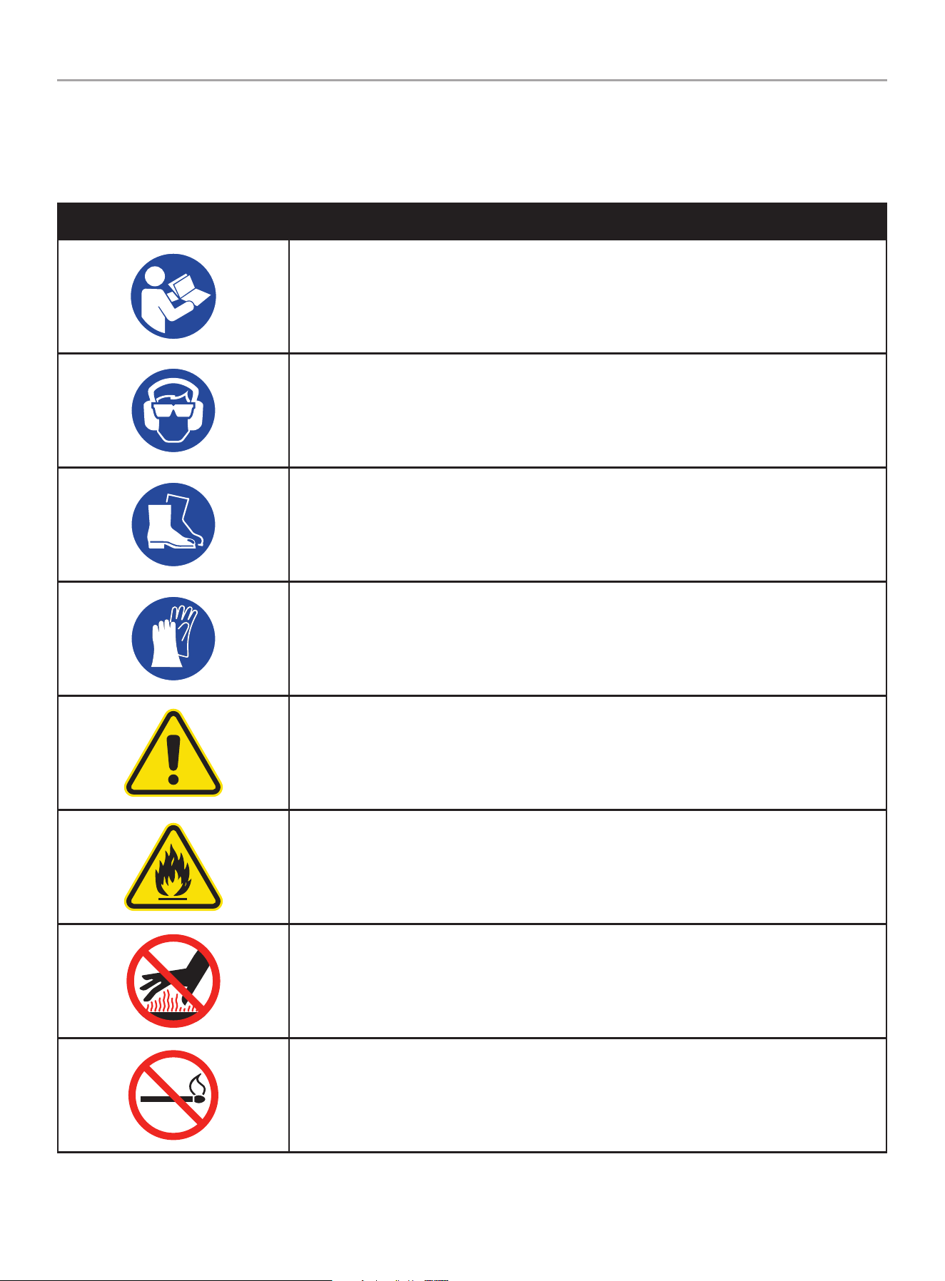
Safety Symbols
Some of the following symbols may be used on this product. Please study them and learn their meaning. Proper interpretation of these
symbols will allow you to more safely operate the product.
SYMBOL MEANING
Read Operator’s Manual. To reduce the risk of injury, user must read and understand operator’s
manual before using this product.
Eye and Ear Protection. Always wear safety goggles or safety glasses with side shields, and as
necessary a full face-shield as well as full ear protection when operating this product.
Footwear. Always wear safety shoes or heavy boots when operating the machine.
Gloves. Always wear nonslip, heavy-duty protective gloves when operating this product.
Safety Alert. Precautions that involve your safety.
Risk of Fire. Fuel and its vapors are extremely flammable and explosive. Fire can cause severe
burns or death. Do not add fuel while the product is operating or still hot.
Hot Surface. To reduce the risk of injury or damage, avoid contact with any hot surface
Open Flame alert. Fuel and its vapors are extremely flammable and explosive. Keep fuel away
from smoking, open flames, sparks, pilot lights, heat, and other ignition sources.
201092 - EARTh AUgER
IMPORTANT SAfETY INSTRUCTIONS
9
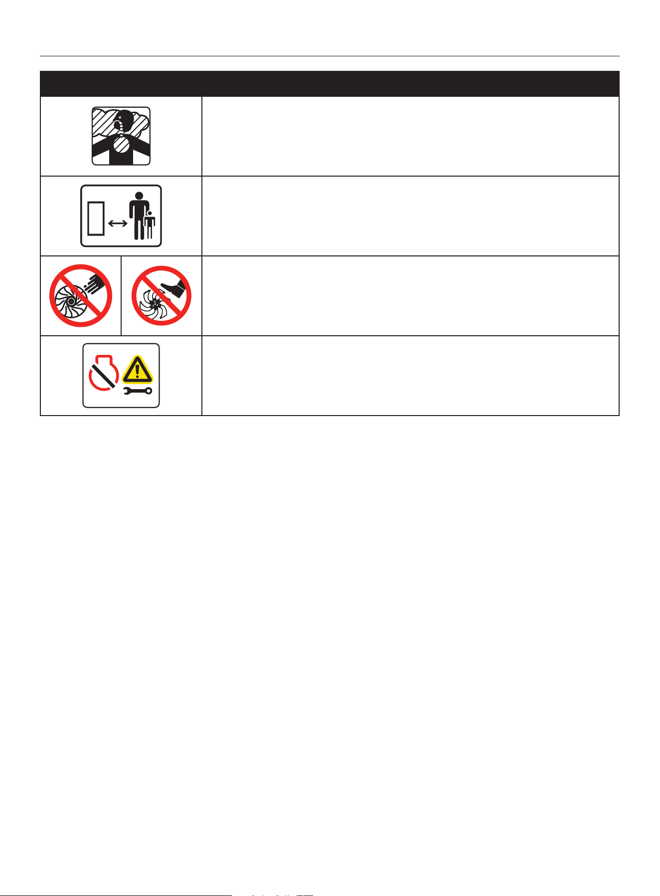
SYMBOL MEANING
Toxic Fumes. The engine exhaust from this product contains chemicals known to the state of
California to cause cancer and birth defects and other reproductive harm.
Risk of Asphyxiation. This engine emits carbon monoxide, an odorless, colorless poison gas.
Breathing carbon monoxide can cause nausea, fainting or death. Use only in a well ventilated
area.
10 ft.
3 m
Clearance. Keep all objects including others at least 10 feet (3m) from this machine.
Only one person should operate the earth auger.
Amputation Hazard. Rotating parts can entangle hands, feet, hair, clothing and/or accessories.
Traumatic amputation or severe laceration can result.
Serious Personal Injury or Property Damage. Before inspecting, cleaning, or servicing the
auger, shut off the engine. Wait for all moving parts to stop, disconnect spark plug wire and move
it away from the spark plug. Failure to follow these instructions could result in personal injury or
damage to the auger.
201092 - EARTh AUgER
IMPORTANT SAfETY INSTRUCTIONS
10
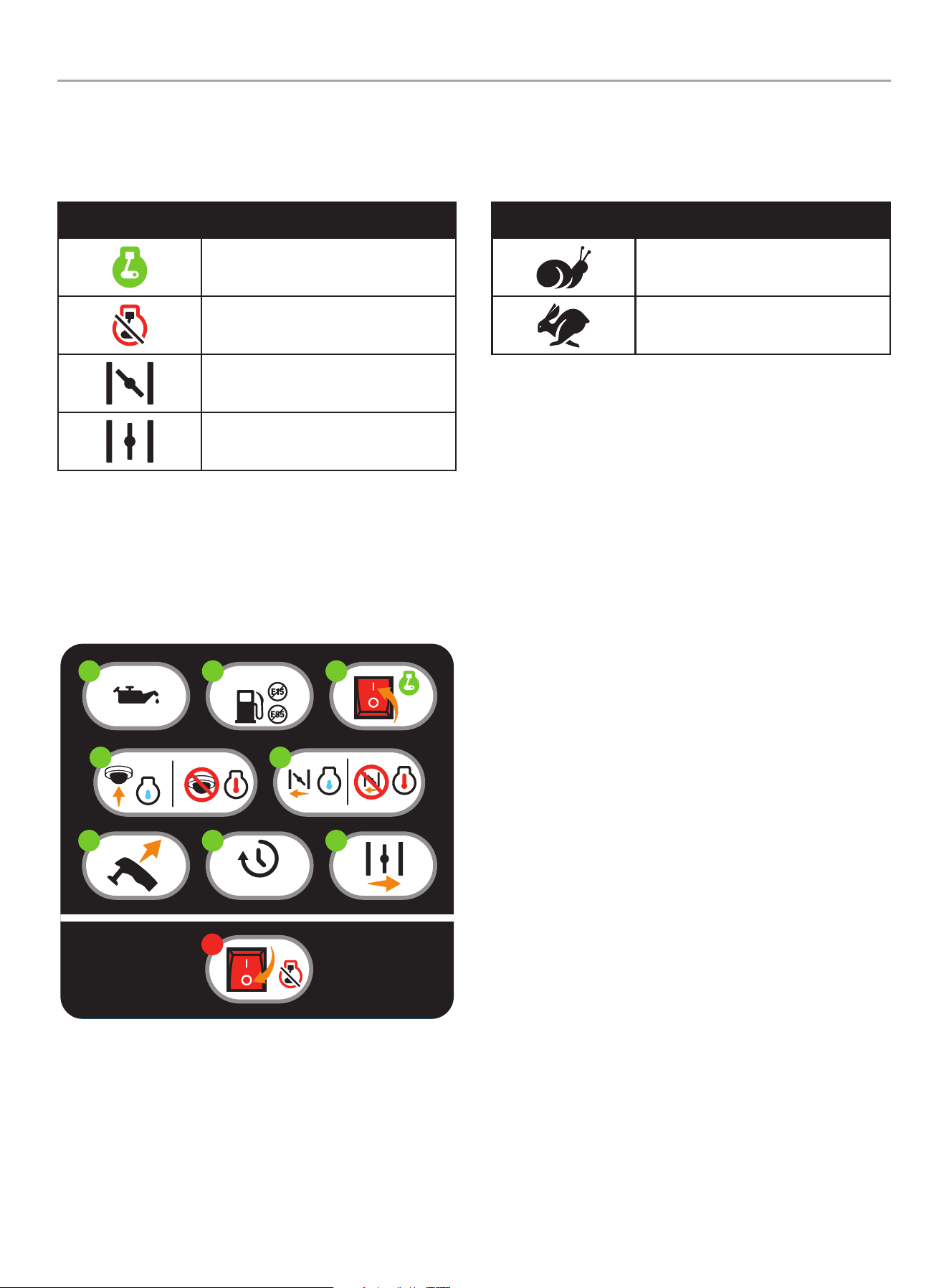
Operation Symbols
Some of the following symbols may be used on this product. Please study them and learn their meaning. Proper interpretation of these
symbols will allow you to more safely operate the product.
SYMBOL MEANING
Engine Switch ON
Engine Switch OFF
Choke
Run
SYMBOL MEANING
Throttle: Slow
Throttle: Fast
Quick Start Label Symbols
Some of the following symbols may be used on this product. Please study them and learn their meaning. Proper interpretation of these
symbols will allow you to more safely operate the product.
Starting the Engine
1. Check Oil Level.
Recommended oil is 5W-30. The engine can be seriously
damaged without oil. Always check the oil level before using.
The machine must be resting firmly on level ground when
checking.
2. Check gasoline level.
When adding gasoline, use a minimum octane rating of 87
and an ethanol content of 10% or less by volume.
3. Press the engine switch to the “ON” position.
4. Primer Bulb: for cold engine, press the primer bulb 7-10
times, or until bulb is full of fuel. (not required for a warm
engine).
5. Choke: For a cold engine, move the choke lever to the
“CHOKE” position. (not required for a warm engine)
6. Pull the recoil starter.
7. Allow the engine to idle for 3-10 seconds.
8. Move the choke lever to the “RUN” position.
Stopping the Engine
1. Press the engine switch to the “OFF” position.
3
4
7-10X
86 7
3-10 s
1
5
3915-L-OP-B
1
5W-30
2
K 485 298 376 ---
ColorsAPN 3915-L-OP
Rev B
Size 60 x 57 mm
Artwork Notes
3mm corner radius; 2mm safe margin;
to be printed
on
WHITE
substrate.
Revision Changes
B:Update step 7 to 3-10s-20231019
This artwork belongs to Champion Power Equipment. The contents are confidential and privileged and shall not be disclosed to or used by or for
outside parties without the explicit consent of Champion Power Equipment.
201092 - EARTh AUgER
CONTROLS AND fEATURES
11
CONTROLS AND fEATURES
Read this operator’s manual before operating your earth auger. Familiarize yourself with the location and function of the controls and
features. Save this manual for future reference.
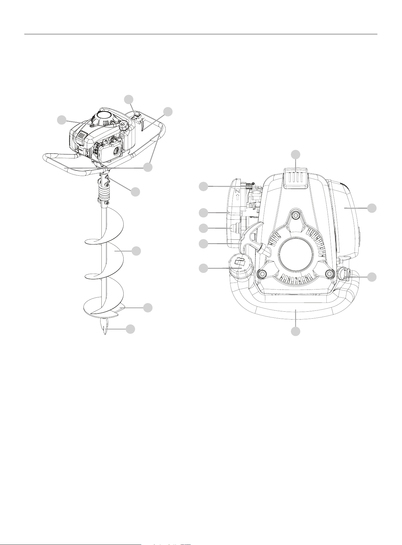
Earth Auger
Auger
1. Throttle/Speed control
2. Engine ON/OFF switch
3. Engine
4. Soft grip handles
5. Clevis pin with double wire snap
6. 8 in. (20.3 cm) Auger bit
7. Earth blade (replaceable)
8. Fishtail bit point (replaceable)
Engine
1. Spark plug
2. Choke lever
3. Air filter
4. Fuel primer bulb
5. Recoil starter handle
6. Fuel tank cap
7. Fuel tank
8. Oil fill cap/dipstick
9. Muffler
1
3
4
5
6
7
8
2
3
4
5
6
8
9
2
1
7
201092 - EARTh AUgER
CONTROLS AND fEATURES
12
Parts Included
Assembly Parts
Part Part Qty. Hardware Needed Hardware Qty. Tool Needed
53.5 cc Auger
Powerhead, handle bars
and grips
1 Clevis pin 1 N/A
8 in. (20.3 cm) Auger bit 1 N/A N/A
Fishtail point 1 N/A Adjustable wrench
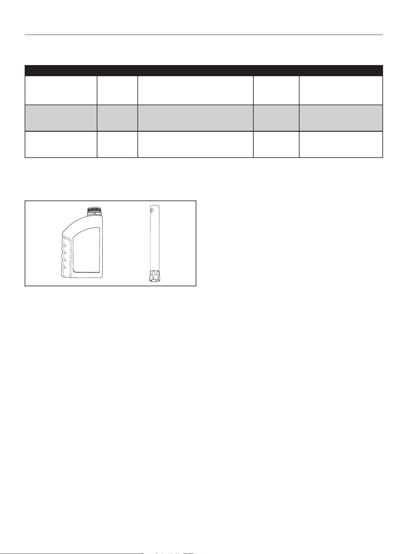
Accessories
Spark plug socket ..................................................1
Engine oil ........................................ 8.1 fl. oz. (240 ml)
Tools Needed
– Adjustable wrench
201092 - EARTh AUgER
ASSEMbLY
13
ASSEMbLY
Your earth auger requires some assembly. This unit ships from our
factory without oil. It must be properly serviced with fuel and oil
before operation.
If you have any questions regarding the assembly of your earth
auger, call our Technical Support Team at 1-877-338-0999.
Please have your serial number and model number available.
Unpacking
1. Set the shipping carton on a solid, flat surface.
2. Remove all contents from the carton.
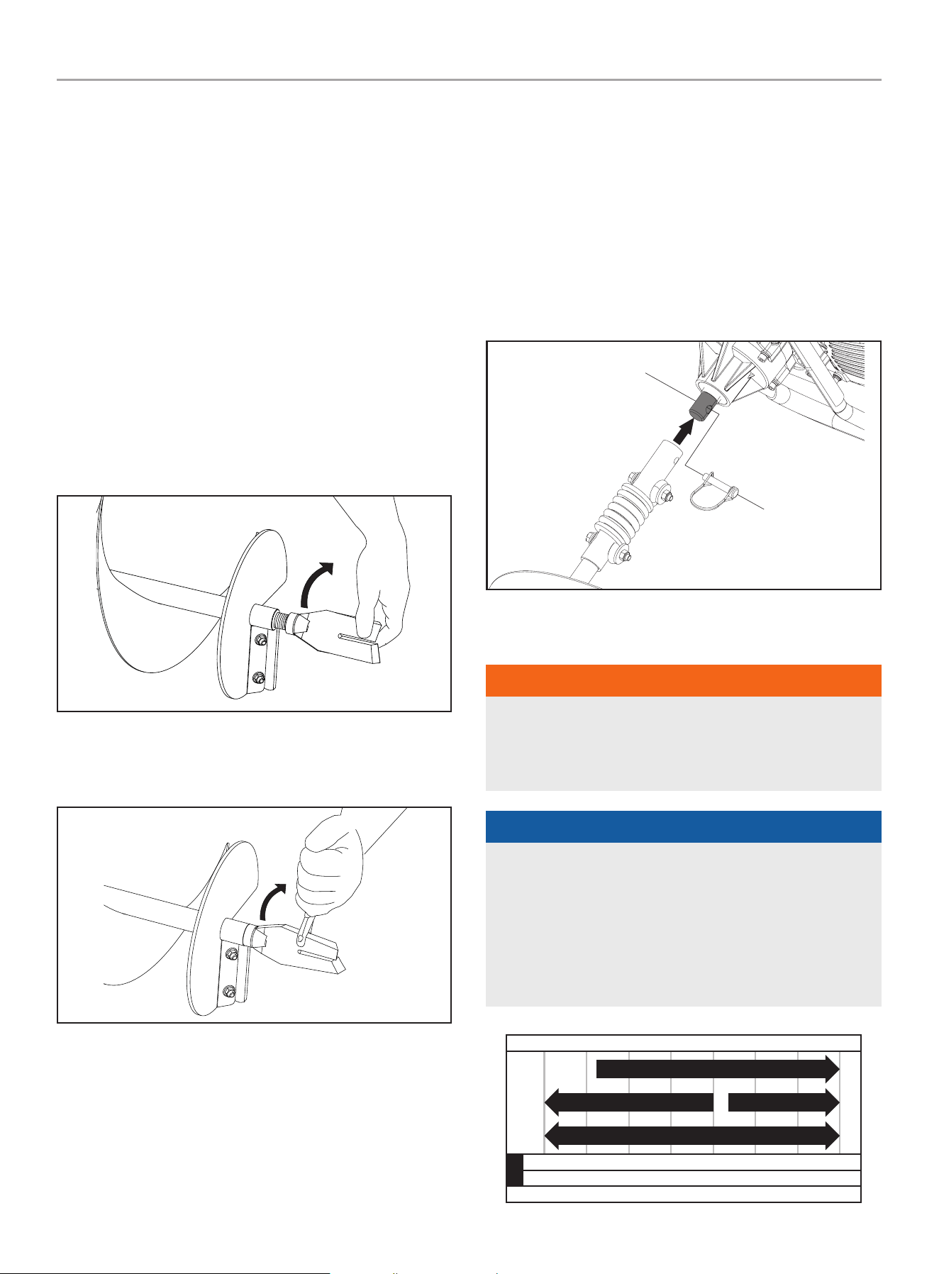
Assemble the fishtail Point to the Auger bit
1. Insert the threaded end of the fishtail point into the threaded
hole on the end of the auger bit and rotate clockwise to hand
tighten.
2. To tighten securely, grasp the auger bit shaft with one hand
while placing an adjustable wrench on the fishtail bit point
and tighten until it is securely in place.
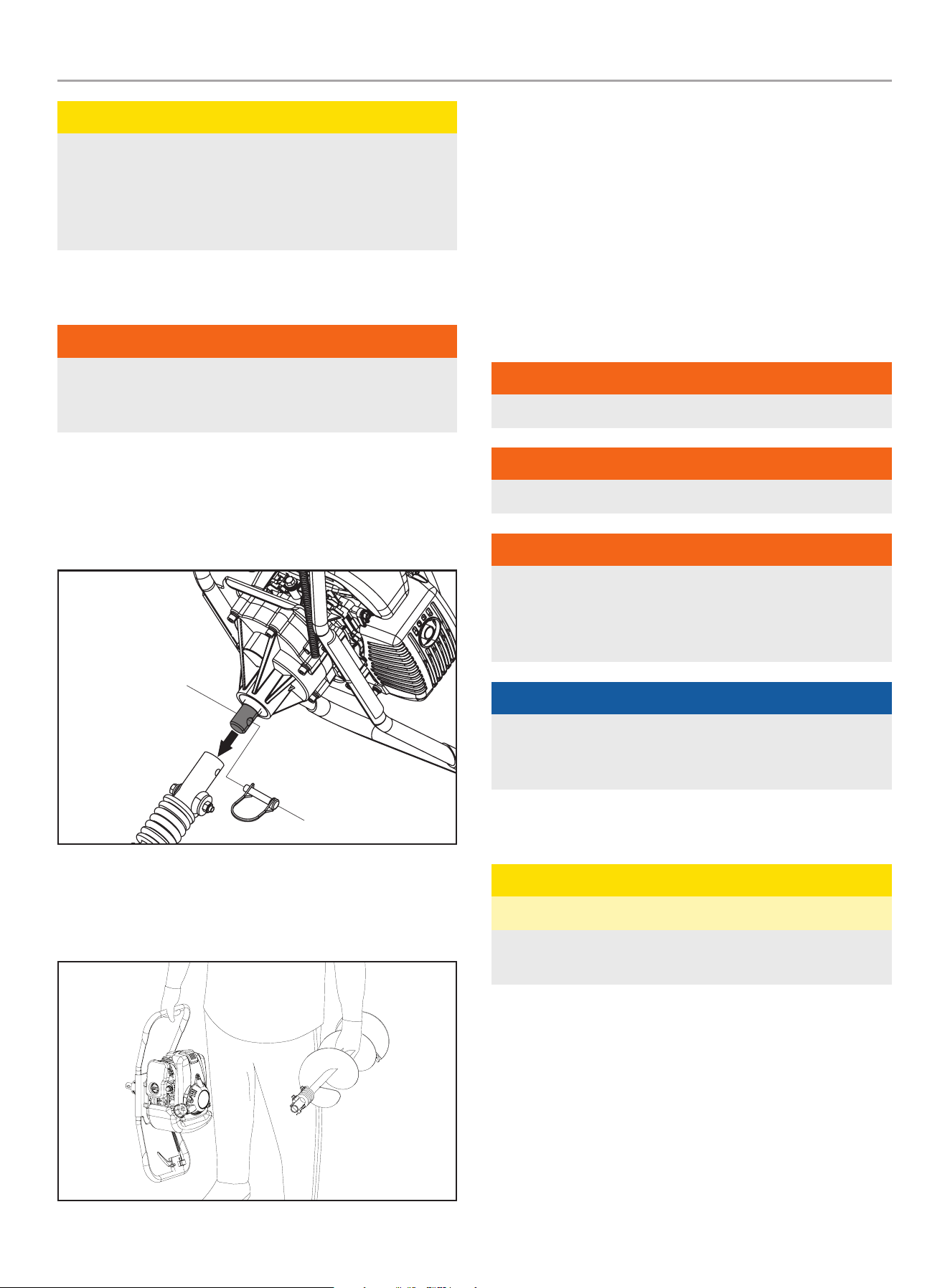
To Assemble Auger bit to Powerhead
1. Insert the power head output shaft into the auger bit shaft
and align the hole in the output shaft with the holes in the
auger bit shaft.
2. Insert the Ø9.5 x 45 mm clevis pin completely through the
aligned holes on the powerhead output shaft and auger bit
tube so it is extended out of the other side.
3. Place the open triangle looped Clevis pin end of the double
wire snap around the exposed end of the Ø9.5 x 45 mm clevis
pin to secure the bit to the power head output shaft.
Add Engine Oil
WARNINg
DO NOT attempt to crank or start the engine before it has been
properly filled with the recommended type and amount of oil.
Damage to the engine as a result of failing to follow these
instructions will void your warranty.
NOTICE
The recommended oil type for typical use is 5W-30
automotive oil. However, using the listed conventional oils
shown in the “Recommended Engine Oil Type” chart may be
used for typical use including the first 5 hours of the break-in
run time period of the engine.
If running engine in extreme temperatures, refer to the
“Recommended Engine Oil Type” chart.
-20 0 20 40 60
Ambient temperature
Recommended Engine Oil Type
80 100 120
-28.9
°F
°C -17.8 -6.7 4.4 15.6 26.7 37.8 48.9
10W-30
5W-30 Full Synthetic
10W-405W-30
201092 - EARTh AUgER
OPERATION
14
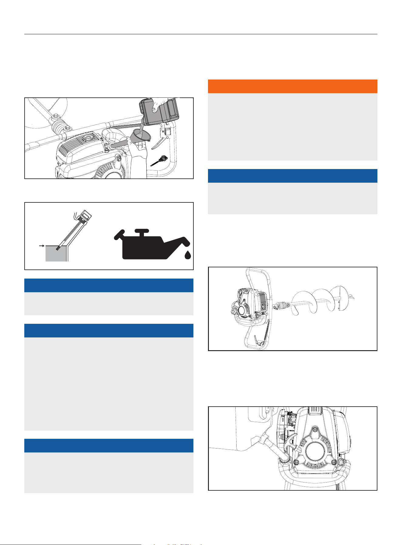
1. Place the earth auger on a flat, level surface with the oil fill
cap facing upward.
2. Remove oil fill cap/dipstick to add oil.
3. Using a funnel, add up to 8.1 fl. oz. (240 ml) of oil (included)
and replace oil fill cap/dipstick. DO NOT OVERFILL.
4. Check engine oil level at every use and add as needed.
MAX
5W-30
DIP STICK
NOTICE
Check oil level often during the break-in period. Refer to the
Maintenance section for recommended service intervals.
NOTICE
We consider the first 5 hours of run time to be the break-
in period for the engine. During the break in period we
recommend using standard automotive non-synthetic blended
oils. After the break in period synthetic lubricant can be used
but is not required. Adjusting throttle setting will increase/
decrease engine speed helping to seat piston rings. Avoid
bogging or lugging the engine down and avoid prolonged
running at constant RPM. After the 5 hour break-in period,
change the oil. Using synthetic lubricants does not increase
the recommended oil change interval.
NOTICE
Synthetic oil may be used after the 5 hour initial break-in
period. Using synthetic oil does not decrease the recommended
oil change interval. Full synthetic 5W-30 oil will aid in starting
in cold ambient < 41º F (5º C) temperatures.
OPERATION
fueling and Refueling
WARNINg
– Do not smoke while fueling or mixing fuel.
– Always mix and pour fuel outdoors away from electrical
appliances where there are no sparks or open flames.
– Never add fuel to a running or hot engine.
– Always wait 15 minutes to cool down engine before
refueling.
NOTICE
DO NOT USE E15 or E85 (fuel containing ethanol greater than
10%) in this engine. Use of gasoline containing more than 10%
ethanol will damage the engine and void your warranty.
Filling the Fuel Tank
1. Place the earth auger on a flat, level surface, resting on the
handle with the throttle/speed control assembled to it so that
the fuel tank cap is pointing upward.
2. Clean the surface around the fuel cap to prevent
contamination.
3. Loosen the fuel cap slowly by turning counterclockwise.
4. Pour the fuel carefully into the tank.
201092 - EARTh AUgER
OPERATION
15
5. Only fill the fuel tank to 80% of the full capacity. Fuel level
can be seen via the clear fuel tank.
6. Clean and inspect the fuel cap gasket before replacing the
fuel cap.
7. Replace the fuel cap and tighten it by turning it clockwise.
8. Wipe spilled fuel from the product.
9. If you spill fuel on the unit, wait 10 minutes for evaporation
after wiping and move at least 10 ft. (3 m) away from the
spilled refueling area before starting the product.
NOTICE
It is normal for smoke to be emitted from a new engine during
first use.
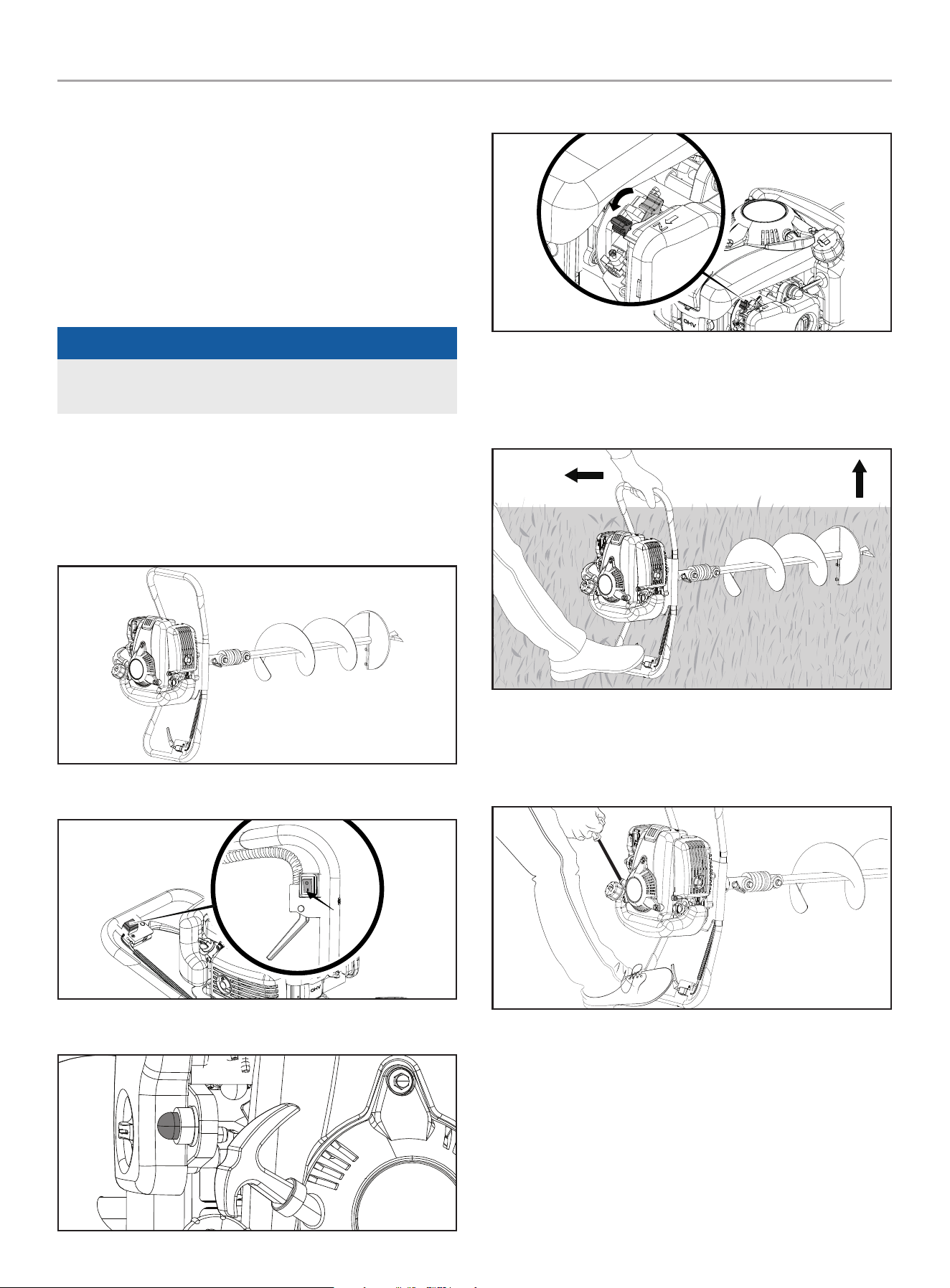
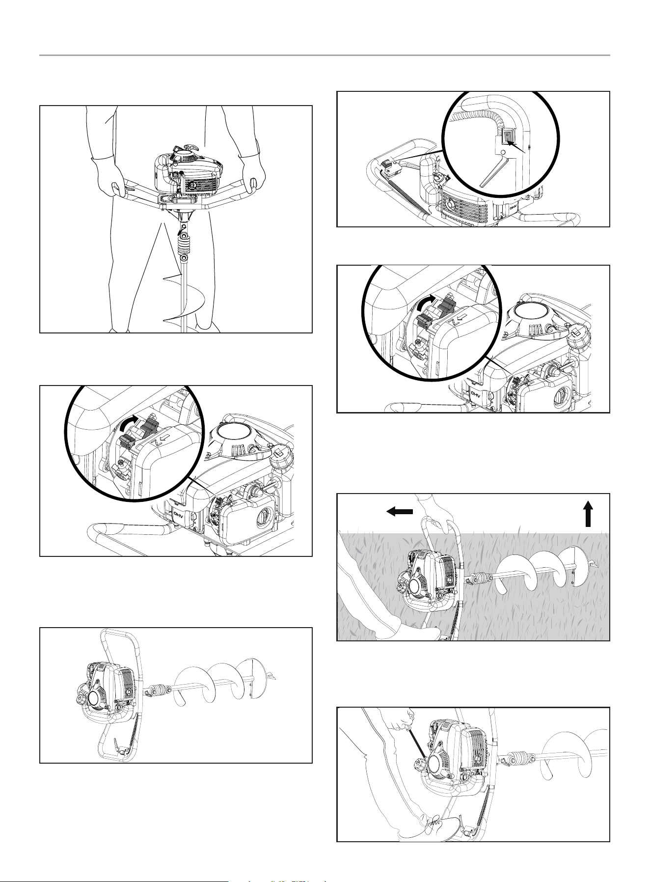
Starting the Engine
Start a Cold Engine
1. Place the handlebar with the throttle/speed control assembly
side flat to the ground surface.
2. Move the engine On/Off switch to the “ON” (I) position.
3. Slowly press the primer bulb 7-10 times or until fuel is visible.
4. Set the choke lever to the “CHOKE” position.
5. While standing on the operator side of the auger, place your
foot on the handlebar that is on the ground to stabilize the
unit. Grip the other handlebar with the other hand and tilt the
auger so that the auger bit is off of the ground.
6. Holding the unit firmly, pull the recoil starter grip 2 times to
prime with fuel, then pull until engine starts. Use short pulls
and do not allow the rope to snap back. Do not pull more than
6 times.
201092 - EARTh AUgER
OPERATION
16
7. Once the engine starts, stand the auger up in the vertical
position and allow to run for 3-10 seconds.
8. After the engine runs for 3-10 seconds, move the choke lever
to the “RUN” position.
Start a Warm Engine
1. Place the handlebar with the throttle/speed control assembly
side flat to the ground surface.
2. Move the engine On/Off switch to the “ON” (I) position.
3. Ensure that the choke lever is in the “RUN” position.
4. While standing on the operator side of the auger, place your
foot on the handlebar that is on the ground to stabilize the
unit. Grip the other handlebar with the other hand and tilt the
auger so that the auger bit is off of the ground.
5. Holding the unit firmly, pull the recoil starter grip until engine
starts. Use short pulls and do not allow the rope to snap
back.
201092 - EARTh AUgER
OPERATION
17
6. Once the engine starts, stand the auger up in the vertical
position.
WARNINg
Rapid retraction of the recoil cord could pull your hand and
arm towards the engine faster than you can let go. Broken
bones, fractures, bruises or sprains could result.
NOTICE
Manually adjusting or turning the choke lever to the CHOKE
position during idle will cause the engine to stop.
NOTICE
If the engine does not start, return to the “Start a Cold Engine”
and repeat the steps that follow.
Stopping the Engine
1. Release the throttle/speed control to stop the auger bit from
rotating.
CAUTION
The auger bit will continue to rotate for a few seconds after the
throttle/speed control is released.
2. Move the engine On/Off switch to the “OFF” (O) position.
WARNINg
If the engine does not stop when the engine switch is moved to
the “STOP” position, release the throttle. Allow the engine to
idle. Put the auger down and slide the choke lever to cold start
(closed) position.
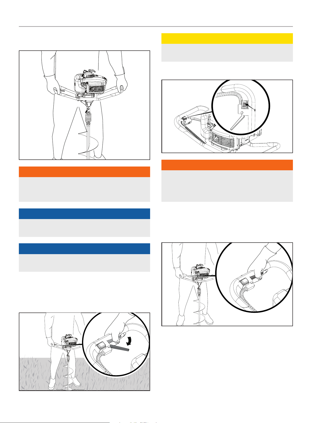
Operating the Auger
1. Holding the unit in the vertical position, place the tip of the
fishtail bit point at the desired drilling location.
2. Engage the throttle/speed control and first start digging the
hole at a slow speed to get a good engagement with the soil.
3. Gradually increase the speed as the auger bit enters the soil.
4. As the auger bit penetrates deeper into the soil, occasionally
lift the auger bit partially up out of the hole to disperse the
loose soil. This will keep the hole free of loose soil and
prevent the auger bit from becoming stuck in the hole. This
will also reduce the time it takes to dig a hole and prevent
overworking the engine.
201092 - EARTh AUgER
MAINTENANCE
18
CAUTION
If the auger bit will not turn in a hole, turn engine off and
remove auger bit from the hole. Check auger bit for damage
and remove any debris from auger bit or hole. Secure spark
plug boot away from the engine and frame to alleviate potential
arcing.
Transporting the Auger
WARNINg
Before transporting the auger, shut off engine and wait for all
moving parts to stop. Failure to follow these instructions could
result in personal injury or property damage.
1. Disassemble the auger bit from the power head by removing
the open triangle looped end of the double wire snap from the
exposed end of the Ø 9.5 x 45 mm clevis pin and removing
the clevis pin from the auger bit and power head output shaft.
This will disengage the bit from the power head output shaft.
2. Carry the power head by the handle that does not have the
throttle/speed control with the recoil starter against your leg
so the fuel tank cap is pointed skyward while carrying the
auger bit in the other hand, held by the shaft.
MAINTENANCE
Make certain that the earth auger is kept clean and stored
properly. Only operate the unit on a flat, level surface in a clean,
dry operating environment. DO NOT expose the unit to extreme
conditions, excessive dust, dirt, moisture or corrosive vapors.
The owner/operator is responsible for all periodic maintenance.
Complete all scheduled maintenance in a timely manner.
Correct any issue before operating the earth auger.
For service or parts assistance, contact our
Technical Support Team at 1-877-338-0999.
WARNINg
Never operate a damaged or defective earth auger.
WARNINg
Improper maintenance will void your warranty.
WARNINg
Before inspecting, cleaning, or servicing the earth auger,
shut off the engine. Wait for all moving parts to stop. Failure
to follow these instructions could result in personal injury or
damage to the earth auger.
NOTICE
For Emission control devices and systems, read and
understand your responsibilities for service as stated in the
Emission Control Warranty Statement of this manual.
Cleaning the Earth auger
CAUTION
DO NOT spray earth auger directly with water.
Water can contaminate the fuel system and can enter the
engine through the cooling slots and damage the engine.
1. Use a damp cloth to clean exterior surfaces of the earth
auger.
2. Use a soft bristle brush to remove dirt and oil.
3. Use an air compressor (25 PSI) to clear dirt and debris from
the earth auger.
4. Inspect all air vents and cooling slots to ensure that they are
clean and unobstructed.
201092 - EARTh AUgER
MAINTENANCE
19
Changing the Engine Oil
WARNINg
DO NOT attempt to crank or start the engine before it has been
properly filled with the recommended type and amount of oil.
Damage to the engine as a result of failing to follow these
instructions will void your warranty.
NOTICE
The recommended oil type is 5W-30 automotive oil.
Change oil when the engine is warm. Refer to the Oil Specification
to select the proper grade for your operating environment.
1. Place the earth auger on a flat, level surface with the drain
plug facing downward.
2. Clean around the oil drain plug to prevent dirt from falling into
the crankcase. Remove oil drain plug with a 10 mm socket
(not included).
3. Allow the oil to drain completely into an appropriate container.
4. Replace the oil drain plug.
5. Remove the oil fill cap/dipstick to add oil.
6. Add oil according to Add Engine Oil in Assembly section. DO
NOT OVERFILL. Oil not included for routine maintenance.
MAX
5W-30
DIP STICK
7. Dispose of used oil at an approved waste management
facility.
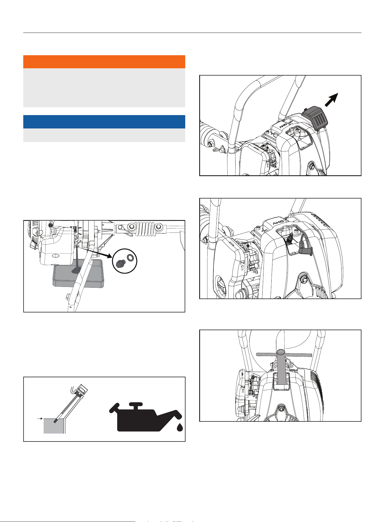
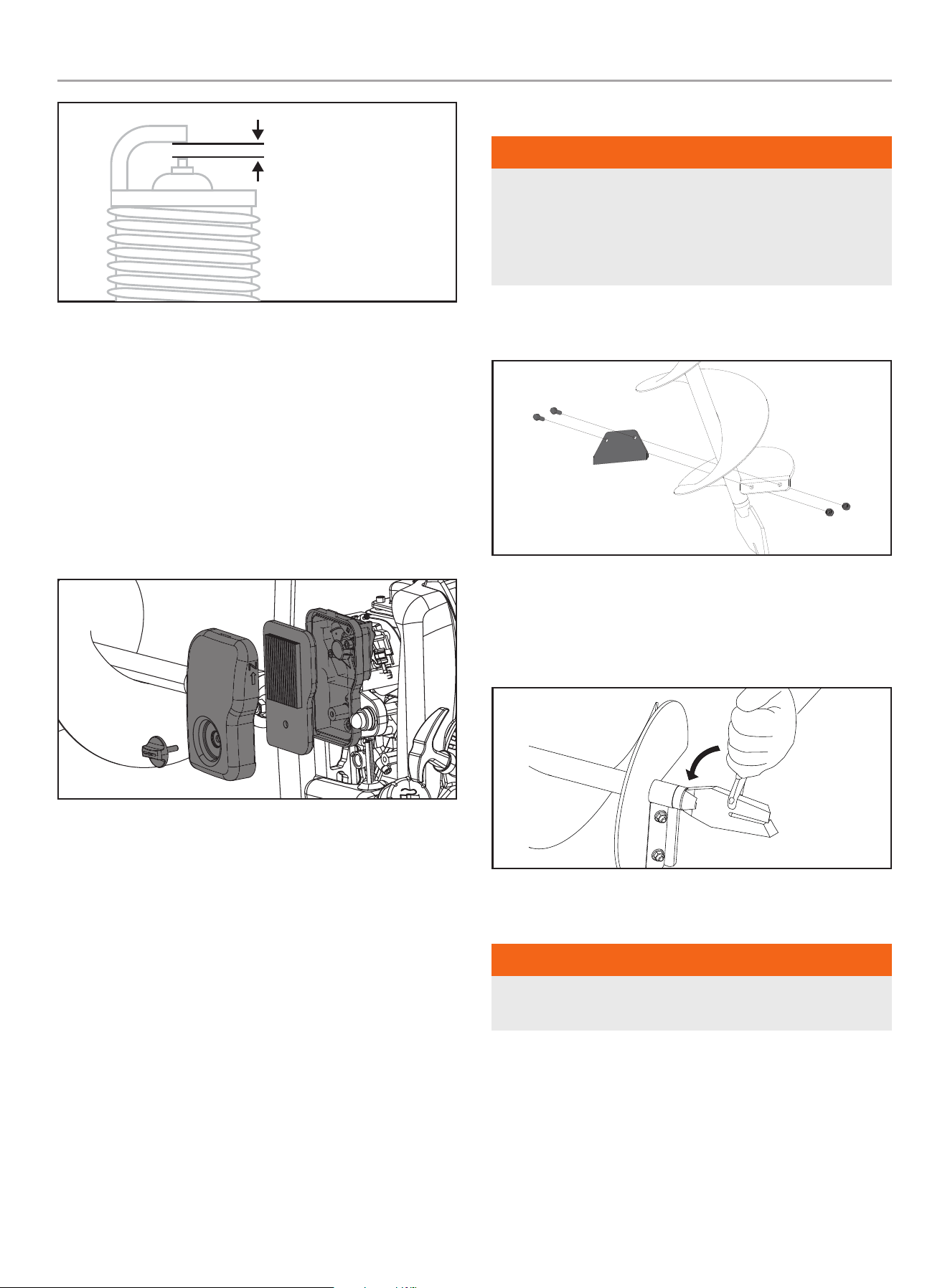
Cleaning and Adjusting the Spark Plug(s)
1. Depress the tab on the spark plug cover then lift upward
removing the cover.
2. Remove the spark plug cable from the spark plug.
3. Use a spark plug socket tool, or a 41/64 in. (16 mm) socket to
remove the plug.
4. Inspect the electrode on the plug. It must be clean and not
worn to produce the spark required for ignition.
5. Make certain the spark plug gap is set within limits. Refer to
the Specifications section for values.
201092 - EARTh AUgER
MAINTENANCE
20
SPARK PLUG GAP
6. Refer to the spark plug types in Specifications when replacing
the plug.
7. Carefully thread the plug into the engine.
8. Use a spark plug socket tool, or a 41/64 in. (16 mm) socket to
install the plug.
9. Attach the spark plug wire to the plug.
Cleaning the Air filter
1. Using your fingers, turn the knob on the air filter cover
counterclockwise to loosen the air filter cover.
2. Remove the paper air filter element.
3. Clean filter by gently tapping it on a flat surface. If very dirty,
replace with a new filter.
4. Place the air filter back into the assembly.
5. Reattach the air filter cover.
Earth blade and fishtail Point
WARNINg
Use only the manufacturer’s replacement part intended for this
auger bit. Do not use any other earth blade, fishtail point or
other branded replacement part to this auger bit which could
result in serious personal injury. Replace worn or damaged
earth blade or fishtail point.
1. Remove the mounting hardware (bolts and nuts), and take off
the earth blade.
2. Install new earth blade with new mounting hardware.
3. Tighten the bolts to secure blade.
4. To replace the fishtail point, use an adjustable wrench to
break it loose.
Adjusting the governor
WARNINg
Tampering with the factory set governor will void your
warranty.
The air-fuel mixture is not adjustable. Tampering with the
factory set governor can damage your earth auger. Contact our
Technical Support Team at 1-877-338-0999 for all other service
and/or adjustment needs.

201092 - EARTh AUgER
STORAgE
21
Maintenance Schedule
Follow the service intervals indicated in the following maintenance
schedule.
Service your earth auger more frequently when operating in
adverse conditions.
Contact our Technical Support Team at 1-877-338-0999 to locate
the nearest CPE certified service dealer for your earth auger or
engine maintenance needs.
BEFORE USE
Check oil level
Wipe up fuel leaks, fuel spillage.
Inspect and clean fuel tank.
25 HOURS
Clean cylinder fins and intake cooling vent.
Inspect and clean the air filter.
EVERY 50 HOURS OR EVERY SEASON
Change oil
Clean and readjust spark plug gap
(gap: 0.6 – 0.8 mm [0.024 – 0.031 in.]), and replace if
necessary.
Inspect and clean the air filter.
ANNUALLY
Replace spark plug.
STORAgE
WARNINg
Never store the auger indoors or next to appliances where
there is a source of heat, open flame, spark or pilot light as
these conditions can ignite gasoline vapors. DO NOT store the
auger near fertilizer or any corrosive material. Even with an
empty fuel tank, gasoline vapors could ignite. When storing
the auger for short or long periods of time, always be sure that
the engine switch (where applicable) and the fuel valve (where
applicable) are set in the “OFF” position.
NOTICE
You can store the unit with ethanol free 50:1 TruFuel gasoline
which is pretreated with advanced stabilizers to safeguard
against water absorption during storage.
NOTICE
The engine works well with 10% or less ethanol blended
gasoline. When using ethanol-blended gasoline there are some
issues worth noting:
Ethanol-blended gasoline can absorb more water than gasoline
alone.
These ethanol blends can eventually separate, leaving
water or a watery goo in the fuel tank, and carburetor. The
compromised gasoline can be drawn into the carburetor and
cause damage to the engine and/or create potential hazards.
If a fuel stabilizer is used, confirm that it is formulated to work
with ethanol-gasoline blends.
– Clean all foreign material from the product. Store idle unit
indoors in a dry, well-ventilated area that is inaccessible to
children. Keep away from corrosive agents such as garden
chemicals and deicing salts.
– Abide by all local regulations for the safe storage and handling
of gasoline.
When storing 1 month or shorter:
– Fuel stabilizer is an acceptable alternative in minimizing the
formation of fuel gum deposits during storage. Add stabilizer to
your fuel container (not the fuel tank on the auger). Run engine
at least 3 minutes after adding stabilizer.
When storing longer than a month:
– Drain all fuel from tank into a container approved for gasoline.
Run engine until it stops.

201092 - EARTh AUgER
SPECIfICATIONS
22
SPECIfICATIONS
Earth Auger Specifications
Model ....................................................... 201092
Auger Bit ............................................. 8 in. (20.3 cm)
Overall Dimensions
Weight ............................................... 35 lbs. (16 kg)
Length ............................................ 48.4 in. (123 cm)
Width .............................................. 25.6 in. (65 cm)
Height ............................................... 10.6 in. (27 cm)
Engine Specifications
Model .....................................................JF144FBV
Displacement ................................................ 53.5 cc
Type ........................................................ 4-Stroke
Spark Plug
OEM Type ...................................................... A7TC
Replacement Type ................................ A7RTC / CR7HSA
Gap ...............................0.023 - 0.031 in. (0.6 - 0.8 mm)
Oil Specifications
DO NOT OVERFILL.
Type ............................................*See following chart
Capacity ......................................... 8.1 fl. oz. (240 ml)
-20 0 20 40 60
Ambient temperature
Recommended Engine Oil Type
80 100 120
-28.9
°F
°C -17.8 -6.7 4.4 15.6 26.7 37.8 48.9
10W-30
5W-30 Full Synthetic
10W-405W-30
NOTICE
Temperature will affect engine oil and engine performance.
Change the type of engine oil used based on temperature
shown in the “Recommended Engine Oil Type” table.
fuel Specifications
Use unleaded gasoline with a minimum octane rating of 87 and
an ethanol content of 10% or less by volume. DO NOT USE E15 or
E85. DO NOT OVERFILL.
Gasoline Capacity ..................................0.32 gal. (1.2 L)
Temperature Specifications
Starting Temperature Range (°F/°C) ........... 5 to 104/-15 to 40
NOTICE
An important message about temperature: Your product
is designed and rated for continuous operation at ambient
temperatures up to 104°F (40°C). When needed, it may be
operated at temperatures ranging from 5°F (-15°C) to 122°F
(50°C) for short periods of time. If exposed to temperatures
outside this range during storage, it should be brought back
within this range before operation. In any event, the product
must always be operated outdoors, in a well-ventilated area
and away from doors, windows and vents.

201092 - EARTh AUgER
TROUbLEShOOTINg
23
TROUbLEShOOTINg
Problem Cause Solution
Engine does not start.
The engine switch is in the “OFF”
position
Move the engine switch to the “ON” position.
Fuel strainer is clogged Clean fuel strainer.
Flooded engine
Let unit sit for 15 minutes or remove spark plug
and clean per the instructions in the Maintenance
section of this operator’s manual.
Spark plug gap is incorrect
Replace or adjust spark plug per the instructions
in the Maintenance section in this operator’s
manual.
Engine will not accelerate, lacks power
or stalls
Choke on Ensure choke lever is in the “RUN” position.
Air filter dirty
Clean air filter per the instructions in the
Maintenance section of this operator’s manual.
Spark plug gap is incorrect
Replace or adjust spark plug per instructions
in the Maintenance section of this operator’s
manual.
Exhaust port/spark arrestor screen
blocked
Clean exhaust port/spark arrestor screen per the
instructions in the Maintenance section of this
operator’s manual.
Engine smokes excessively Air filter dirty
Clean the air filter per the instructions in the
Maintenance section of this operator’s manual.
Auger bit turns while engine is idling
Idle speed is too high. Carburetor needs
adjustment.
Call for free technical service at 1-877-338-0999
For other issues and technical support:
Technical Support Team
Toll Free 1-877-338-0999
support@championpowerequipment.com

WARRANTY*
CHAMPION POWER EQUIPMENT
2 YEAR LIMITED WARRANTY
Warranty Qualifications
To register your product for warranty and FREE lifetime call center
technical support please visit:
https://www.championpowerequipment.com/register
To complete registration you will need to include a copy of the
purchase receipt as proof of original purchase. Proof of purchase
is required for warranty service. Please register within ten (10)
days from date of purchase.
Repair/Replacement Warranty
CPE warrants to the original purchaser that the mechanical and
electrical components will be free of defects in material and
workmanship for a period of two years (parts and labor) from
the original date of purchase and 180 days (parts and labor) for
commercial and industrial use. Transportation charges on product
submitted for repair or replacement under this warranty are the
sole responsibility of the purchaser. This warranty only applies to
the original purchaser and is not transferable.
Do Not Return The Unit To The Place Of
Purchase
Contact CPE’s Technical Service and CPE will troubleshoot any
issue via phone or e-mail. If the problem is not corrected by
this method, CPE will, at its option, authorize evaluation, repair
or replacement of the defective part or component at a CPE
Service Center. CPE will provide you with a case number for
warranty service. Please keep it for future reference. Repairs or
replacements without prior authorization, or at an unauthorized
repair facility, will not be covered by this warranty.
Warranty Exclusions
This warranty does not cover the following:
Normal Wear
Products with mechanical and electrical components need
periodic parts and service to perform well. This warranty does not
cover repair when normal use has exhausted the life of a part or
the equipment as a whole.
Installation, Use and Maintenance
This warranty will not apply to parts and/or labor if the product is
deemed to have been misused, neglected, involved in an accident,
abused, loaded beyond the product’s limits or modified. Normal
maintenance is not covered by this warranty and is not required to
be performed at a facility or by a person authorized by CPE.
Other Exclusions
This warranty excludes:
– Cosmetic defects such as paint, decals, etc.
– Wear items such as starter pulleys, starter ropes, filter
elements, auger bits, earth blades, and fishtail blades.
– Failures due to acts of God and other force majeure events
beyond the manufacturer’s control.
– Problems caused by parts that are not original Champion
Power Equipment parts.
Limits of Implied Warranty and
Consequential Damage
Champion Power Equipment disclaims any obligation to cover
any loss of time, use of this product, freight, or any incidental
or consequential claim by anyone from using this product.
THIS WARRANTY AND THE ATTACHED U.S. EPA and/or CARB
EMISSION CONTROL SYSTEM WARRANTIES (WHEN APPLICABLE)
ARE IN LIEU OF ALL OTHER WARRANTIES, EXPRESS OR IMPLIED,
INCLUDING WARRANTIES OF MERCHANTABILITY OR FITNESS
FOR A PARTICULAR PURPOSE.
A unit provided as an exchange will be subject to the warranty
of the original unit. The length of the warranty governing the
exchanged unit will remain calculated by reference to the purchase
date of the original unit.
This warranty gives you certain legal rights which may change
from state to state or province to province. Your state or province
may also have other rights you may be entitled to that are not
listed within this warranty.
Contact Information
Address
Champion Power Equipment, Inc.
6370 S Pioneer Way, Unit 101
Las Vegas, NV 89113 USA
www.championpowerequipment.com
Customer Service
Toll Free: 1-877-338-0999
info@championpowerequipment.com
Fax no.: 1-562-236-9429
Technical Service
Toll Free: 1-877-338-0999
tech@championpowerequipment.com
EMERGENCY 24 HOUR SUPPORT: 1-562-204-1188
*Except as otherwise stipulated in any of the following enclosed Emission Control System Warranties (when applicable) for the Emission Control System: U.S. Environment Protection Agency
(EPA) and/or California Air Resources Board (CARB).

CHAMPION POWER EQUIPMENT, INC. (CPE),
THE UNITED STATES ENVIRONMENTAL PROTECTION AGENCY (U.S. EPA)
EMISSION CONTROL SYSTEM WARRANTY
Your Champion Power Equipment (CPE) engine complies with U.S. EPA emissions regulations.
YOUR WARRANTY RIGHTS AND OBLIGATIONS:
The U.S. EPA and Champion Power Equipment (CPE) are pleased to explain the Federal Emission Control System’s Warranty on your
2023 small off-road engine and engine powered equipment. In the United States new equipment that use small off-road engines shall be
designed, built and equipped to meet U.S. EPA regulations.
CPE shall warrant the emission control system on your small off-road engine and equipment for the period of listed below, provided there
has been no abuse, neglect, unapproved modification or improper maintenance of your equipment.
Your emission control system may include parts such as: carburetor, fuel tanks, fuel lines (for liquid fuel and fuel vapors), fuel caps, valves,
canisters, filters, clamps, connectors, and other associated components. Where a warrantable condition exits, CPE will repair your small
off-road engine at no cost to you including diagnosis, parts and labor.
MANUFACTURER’S WARRANTY COVERAGE:
This emission control system is warranted for two years. If any emission related part on your engine or equipment is defective, the part will
be repaired or replaced by CPE.
OWNER’S WARRANTY RESPONSIBILITIES:
As the small off-road engine owner, you are responsible for the performance of the required maintenance listed in your Owner’s Manual.
CPE recommends that you retain all your receipts covering maintenance on your small off-road engine, but CPE cannot deny warranty
solely for the lack of receipts.
As the small off-road engine owner, you should be aware that CPE may deny you warranty coverage if your small off-road engine or a part
has failed due to abuse, neglect, or improper maintenance or unapproved modifications.
You are responsible for presenting your small off-road engine to an Authorized CPE distribution center or service center or alternate service
outlet as soon as a problem exists. The warranty repairs shall be completed in a reasonable amount of time, not to exceed 30 days.
If you have any questions regarding your warranty coverage, you should contact:
Champion Power Equipment, Inc.
Customer Service
6370 S Pioneer Way, Unit 101
Las Vegas, NV 89113
1-877-338-0999
tech@championpowerequipment.com

EMISSION CONTROL SYSTEM WARRANTY
1. APPLICABILITY: This section applies to Emissions Control Systems on small off-road engines or equipment that use small off-road
engines subject to the emission standards in this Article. The warranty period begins on the date the new engine or equipment is
delivered to an ultimate purchaser and shall continue for 24 consecutive months thereafter.
2. GENERAL EMISSIONS WARRANTY COVERAGE
CPE warrants to the ultimate purchaser of the new engine or equipment and to each subsequent owner that the Emissions Control
System when installed is:
2a. Designed, built and equipped to conform to U.S. EPA emissions standards for spark-ignited engines at or below 19 kilowatts;
2b. Free from defects in materials and workmanship that cause the failure of a warranted part to be identical in all material respects
to the part as described in the engine manufacturer’s application for certification for a period of two years.
3. THE WARRANTY ON EXHAUST AND EVAPORATIVE EMISSION-RELATED PARTS WILL BE INTERPRETED AS FOLLOWS:
3a. Any warranted part that is not scheduled for replacement as required maintenance in the Operators Manual required by subsection
(e) must be warranted for the warranty period defined in subsection (b)(2). If any such part fails during the period of warranty
coverage, it must be repaired or replaced by CPE according to subsection (3)(3d) below. Any such part repaired or replaced under
the warranty must be warranted for a time not less than the any remaining warranty period.
3b. Any warranted emissions-related part that is scheduled only for regular inspection in the Operators Manual shall be warranted
for the warranty period defined in subsection (b)(2). A statement in such written instructions to the effect of “repair or replace as
necessary” shall advise owners of the warranty coverage for emissions related parts. Replacement within the warranty period is
covered by the warranty and will not reduce the period of warranty coverage. Any such emission-related part repaired replaced
under warranty shall be warranted for a time not less than the remaining warranty period.
3c. Any warranted emissions-related part that is scheduled for replacement as required maintenance in the Operators Manual shall
be warranted for the period of time prior to the first scheduled replacement point for that part. If the part fails prior to the first
scheduled replacement, the part shall be repaired or replaced by CPE according to Subsection (3)(3d) below. Any such emissions-
related part repaired or replaced under warranty shall be warranted for a time not less than the remainder of the period prior to
the first scheduled replacement point for such emissions-related part.
3d. Repair or replacement of any warranted emissions-related part under the Warranty provisions of this article shall be performed at
no charge to the owner at a CPE Authorized Service Outlet.
3e. The owner of the small off-road engine shall not be charged for diagnostic labor that leads to the determination that a warranted
part is in fact defective, provided that such diagnostic work is performed at a CPE Authorized Service Outlet.
3f. CPE shall pay for covered emissions warranty repairs at non-authorized service outlets under the following circumstances:
i. The service is required in a population center with a population over 100,000 according to U.S. Census 2000 without a CPE
Authorized Service Outlet AND
ii. The service is required more than 100 miles from a CPE Authorized Service Outlet. The 100-mile limitation does not apply in the
following states: Alaska, Arizona, Colorado, Hawaii, Idaho, Montana, Nebraska, Nevada, New Mexico, Oregon, Texas, Utah and
Wyoming.
3g. CPE shall be liable for damages to other original engine components or approved modifications proximately caused by a failure
under warranty of an emission-related part covered by the ECS Warranty.
3h. Throughout the Emissions Control Systems Warranty period, CPE shall maintain a supply of warranted emission-related parts
sufficient to meet the expected demand for such emission-related parts.
3i. Any CPE Authorized, and approved emission-related replacement part may be used in the performance of any ECS Warranty
maintenance or repair and will be provided without charge to the owner. Such use shall not reduce CPE’s warranty obligation.
3j. Unapproved add-on or modified parts may not be used to modify or repair a CPE engine. Such use voids this Warranty and shall
be grounds for disallowing a warranty claim. CPE shall not be liable hereunder for failures of any warranted parts of a CPE engine
caused by the use of such an unapproved add-on or modified part.

EMISSION-RELATED PARTS INCLUDE THE FOLLOWING: (using those portions of the list applicable to the
engine)
Systems covered by this
warranty
Parts Description
Fuel Metering System Fuel regulator, Carburetor and internal parts
Air Induction System Air cleaner, Intake manifold
Ignition System Spark plug and parts, Magneto ignition system
Exhaust System Exhaust manifold, catalytic converter
Miscellaneous Parts Tubing, Fittings, Seals, Gaskets, and Clamps associated with these listed systems.
Evaporative Emissions Fuel Tank, Fuel Cap, Fuel Lines (for liquid fuel and fuel vapors), Fuel Line Fittings, Clamps, Pressure
Relief Valves, Control Valves, Control Solenoids, Electronic Controls, Vacuum Control Diaphragms,
Control Cables, Control Linkages, Purge Valves, Gaskets, Liquid/Vapor Separator, Carbon Canister,
Canister Mounting Brackets, Carburetor Purge Port Connector
TO OBTAIN WARRANTY SERVICE:
You must take your CPE engine or the product on which it is installed, along with your warranty registration card or other proof of original
purchase date, at your expense, to any Champion Power Equipment dealer who is authorized by Champion Power Equipment, Inc. to sell
and service that CPE product during normal business hours. Alternate service locations defined in Section (3)(f.) above must be approved
by CPE prior to service. Claims for repair or adjustment found to be caused solely by defects in material or workmanship will not be denied
because the engine was not properly maintained and used.
If you have any questions regarding your warranty rights and responsibilities, or to obtain warranty service, please write or call
Customer Service at Champion Power Equipment, Inc.
Champion Power Equipment, Inc.
6370 S Pioneer Way, Unit 101
Las Vegas, NV 89113
1-877-338-0999
Attn.: Customer Service
tech@championpowerequipment.com