Instruction Sheet
Stand & Tray
for 5-Ton Log Splitter
____________________________
Model #: 32230
Control #’s: 32234 *
Fiche d’instructions
Piètement et plateau
pour fendeuse de bûches 5 tonnes
____________________________
Modèle n°: 32230
N° de contrôle: 32234 *
Hoja de instrucciones
Soporte y bandeja
para partidor de leña de 5 toneladas
____________________________
N.º de modelo: 32230
N.º de control: 32234 *
* The rst six digits of the product’s serial number are the control number.
* Les six premiers chires du numéro de série du produit correspondent au numéro de contrôle.
* Los primeros seis dígitos del número de serie del producto son el número de control.
ENGLISHFRANÇAISESPAÑOL
Get parts or technical assistance online at
www.getearthquake.com or call (800) 345-6007
Pièces détachées et assistance technique en ligne à
www.getearthquake.com ou composer le (800) 345-6007
Obtenga piezas o asistencia técnica en línea en
www.getearthquake.com o llame al (800) 345-6007
© 2023 Ardisam
All Rights Reserved
Tous droits réservés
Todos los derechos reservados
P/N: 34098-REV4:
08/02/2023
Réf.: 34098-REV4:
08/02/2023
N.º/P: 34098-MOD4:
08/02/2023
ECN: 14179
2 Get parts online at www.getearthquake.com or Call 800-345-6007 M-F 8-4:30 CST
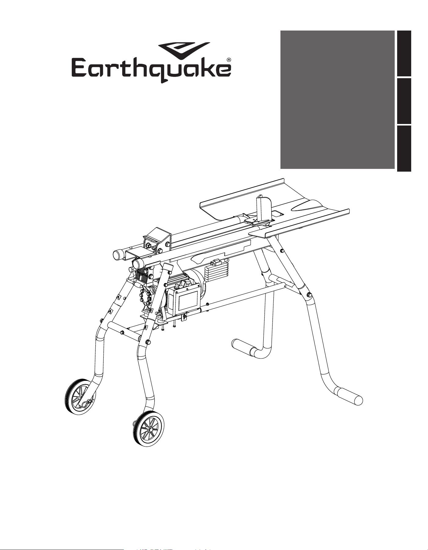
Assembly Instructions
5-TON ELECTRIC LOG SPLITTER STAND AND TRAY
7
18
20
1
25
6
12
16
17
11
22
21
8
13
19
10
2
3
5
15
24
14
23
9
4

3
Get parts online at www.getearthquake.com or Call 800-345-6007 M-F 8-4:30 CST
Assembly Instructions
5-TON ELECTRIC LOG SPLITTER STAND AND TRAY
ITEM NO. PART NO. DESCRIPTION QTY
1 34196 W500 STAND REAR LEFT LEG WITH DECAL 1
2 34197 W500 STAND REAR RIGHT LEG WITH DECAL 1
3 34199 W500 STAND FRONT RIGHT LEG WITH DECAL 1
4 34198 W500 STAND FRONT LEFT LEG WITH DECAL 1
5 33777 WELDMENT TUBE 25.1.5X513.2 MM W/ SPACER 1
6 33734 WELDMENT W500 STAND LEG CONNECTION ROD 1
7 33734 WELDMENT W500 STAND LEG CONNECTION ROD 1
8 33735 WELDMENT MOTOR SUPPORT W500 STAND 1
9 33669 WHEEL AXLE ASSY W500 1
10 34203 W500 LOG TRAY WITH DECAL 1
11 W1265V0902 BOLT M10X1.5X70 MM HHCS GR8.8 ZN P-T 4
12 21718 BOLT M8X1.25X50 MM HHCS GR8.8 ZN F-T 2
13 33742 BOLT M6X1.0X45 MM HHCS GR8.8 ZN F-T 2
14 331059 BOLT M6X1.0X60 MM HH GR8.8 ZN F-T 2
15 31948 NUT M6X1X4.2 MM H GR8.8 ZN 2
16 W1200126 WASHER M10X21.25X1.33 MM GR8.8 ZN 4
17 W1200119 WASHER M10X18.1X2 MM SPRLK ZN 4
18 20143 WASHER M8X16X1.5 MM GR8.8 ZN 2
19 W1200117 WASHER M6X12X1.00 MM GR8.8 ZN 4
20 32569 WASHER M8X1.25X2.1 MM SPRLK GR8.8 ZN 2
21 W1200116 WASHER M6X11.8X1.5 MM SPRLK GR8.8 ZN 2
22 46134 HAIRPIN 0.148 DIA X 0.75 SHAFT OD 2
23 34778 WELDMENT TUBE 25.1.5X513.2 MM SWEDGE END W/
SPACER
1
24 18104 BOLT M6X1.0X35 MM HHCS GR8.8 ZN F-T 1
25 W1265V0913 NUT M6X1.0X8 MM HNYLK CL8 ZN 1

4 Get parts online at www.getearthquake.com or Call 800-345-6007 M-F 8-4:30 CST
Assembly Instructions
5-TON ELECTRIC LOG SPLITTER STAND AND TRAY
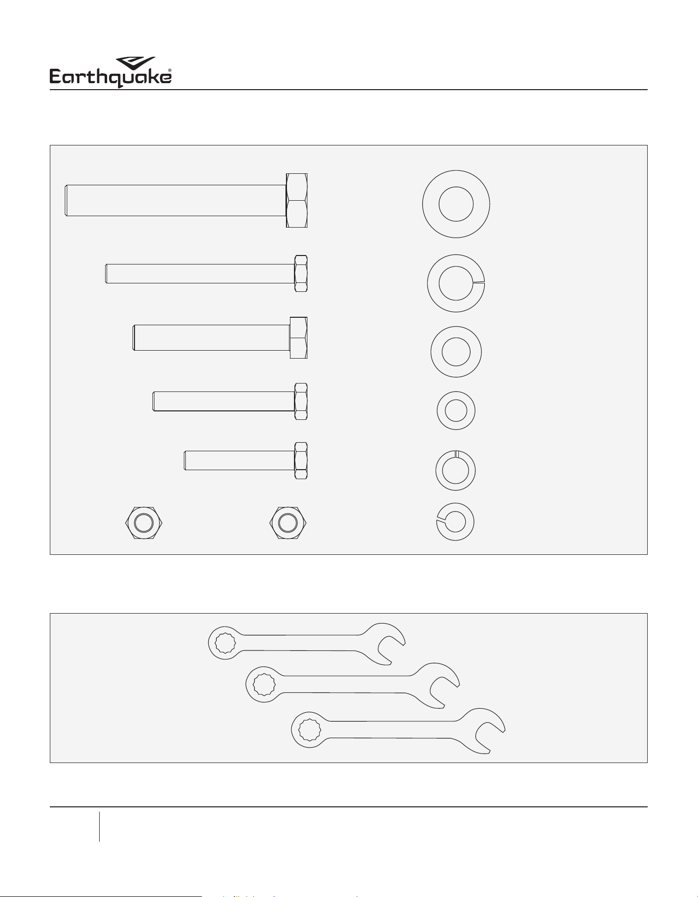
Installation of Stand:
Open the hardware bag and identify all the hardware as shown above.
(16)
M10 x 21.25 MM Washer
Qty 4
(17)
M10 x 18 MM Washer
Qty 4
(18)
M8 x 16 MM Washer
Qty 2
(19)
M6 x 12 MM Washer
Qty 4
(20)
M8 x 1.25 MM Washer
Qty 2
(11)
M10 x 70 MM Bolt
Qty 4
(14)
M6 x 60 MM Bolt
Qty 2
(12)
M8 x 50 MM Bolt
Qty 2
(13)
M6 x 45 MM Bolt
Qty 2
(15)
M6 x 4.2 MM Nut
Qty 2
(25)
M6 x 8 MM Nylock Nut
Qty 1
(21)
M6 x 11.8 MM Washer
Qty 2
(24)
M6 x 35 MM Bolt
Qty 1
Wrench sizes needed: 10mm, 14mm, 17mm
14 MM Wrench
17 MM Wrench
10 MM Wrench

5
Get parts online at www.getearthquake.com or Call 800-345-6007 M-F 8-4:30 CST
Assembly Instructions
5-TON ELECTRIC LOG SPLITTER STAND AND TRAY
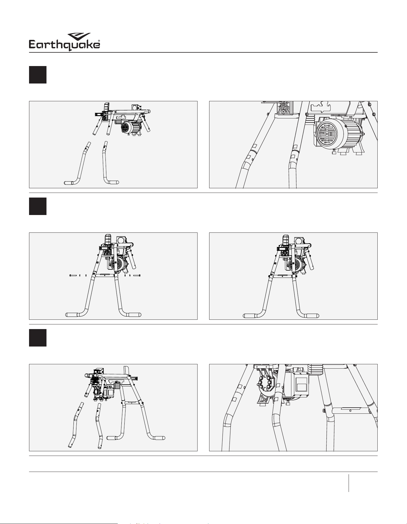
Lift the log splitter from the wedge end and insert the rear legs (1 & 2) making sure the letters on the decals match and the
decals align as in gures 2 and 3.
1
Fig. 3Fig. 2
Using two of the M10 bolts (11), M10 at washer (16) and M10 spring lock washer (17), install the cross beam (6) between
the rear legs (1 & 2). The hardware should be loose installed. Cross beam (6) is identied by the decal referencing a lifting
location for the log splitter for transport.
2
Fig. 5Fig. 4
Lift the pump end and insert the front legs (3 & 4) making sure the decals are aligned.
3
Fig. 7Fig. 6

6 Get parts online at www.getearthquake.com or Call 800-345-6007 M-F 8-4:30 CST
Assembly Instructions
5-TON ELECTRIC LOG SPLITTER STAND AND TRAY
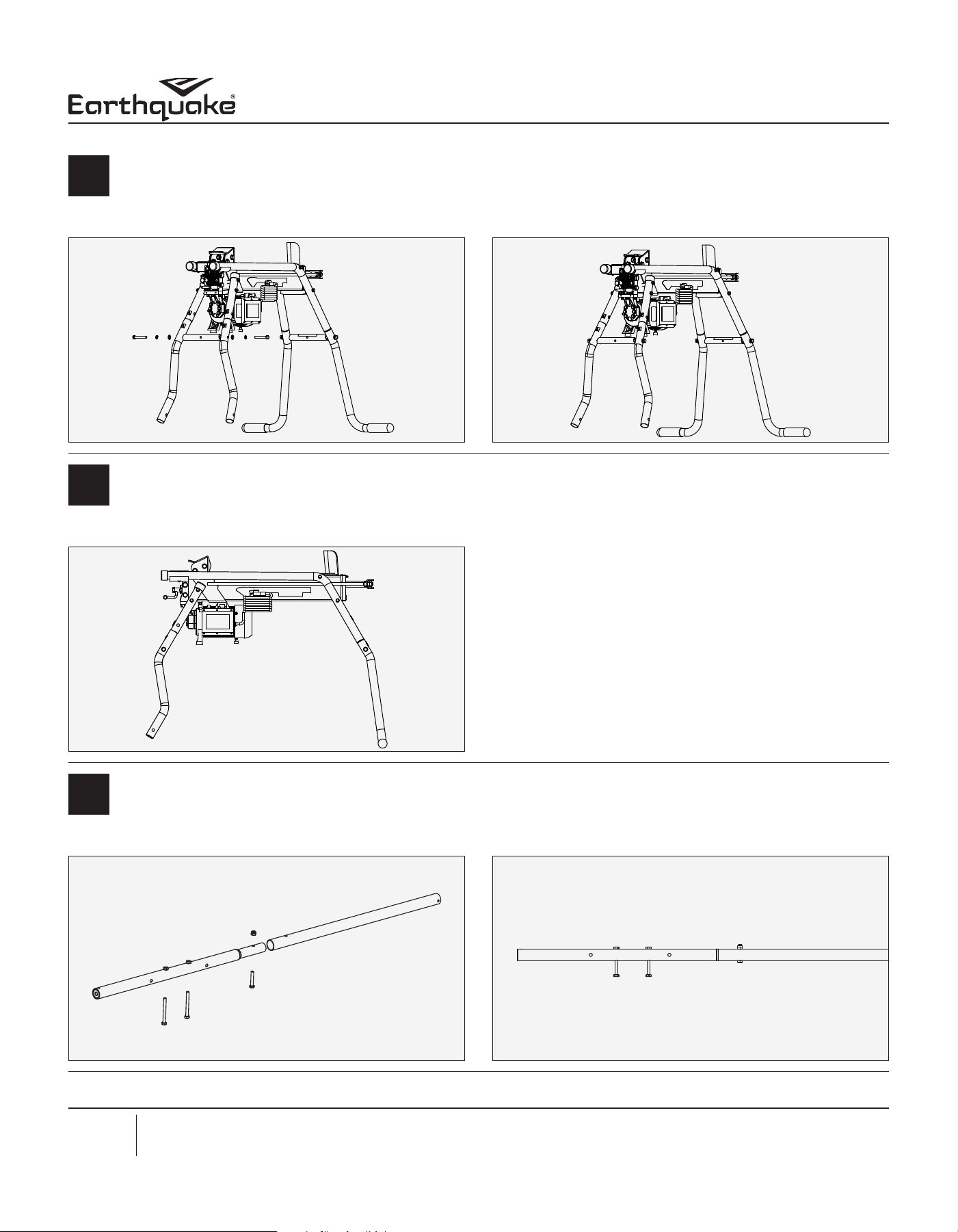
Using two of the M10 bolts (11), M10 at washers (16) and M10 spring lock washer (17), install the cross beam (7) between
the front legs (3 & 4). The hardware should be loose installed.
4
Fig. 9Fig. 8
After installing legs look at the unit from a side view. It should look similar to gure 10.
5
Fig. 10
Using M6 bolts (14, 24) and M6 nut (25), fasten to central rods (5 & 23) as shown in gure 11. At this stage the bolts should
not be protruding out of the weld nuts, as shown in gure 12.
6
Fig. 12Fig. 11

7
Get parts online at www.getearthquake.com or Call 800-345-6007 M-F 8-4:30 CST
Assembly Instructions
5-TON ELECTRIC LOG SPLITTER STAND AND TRAY
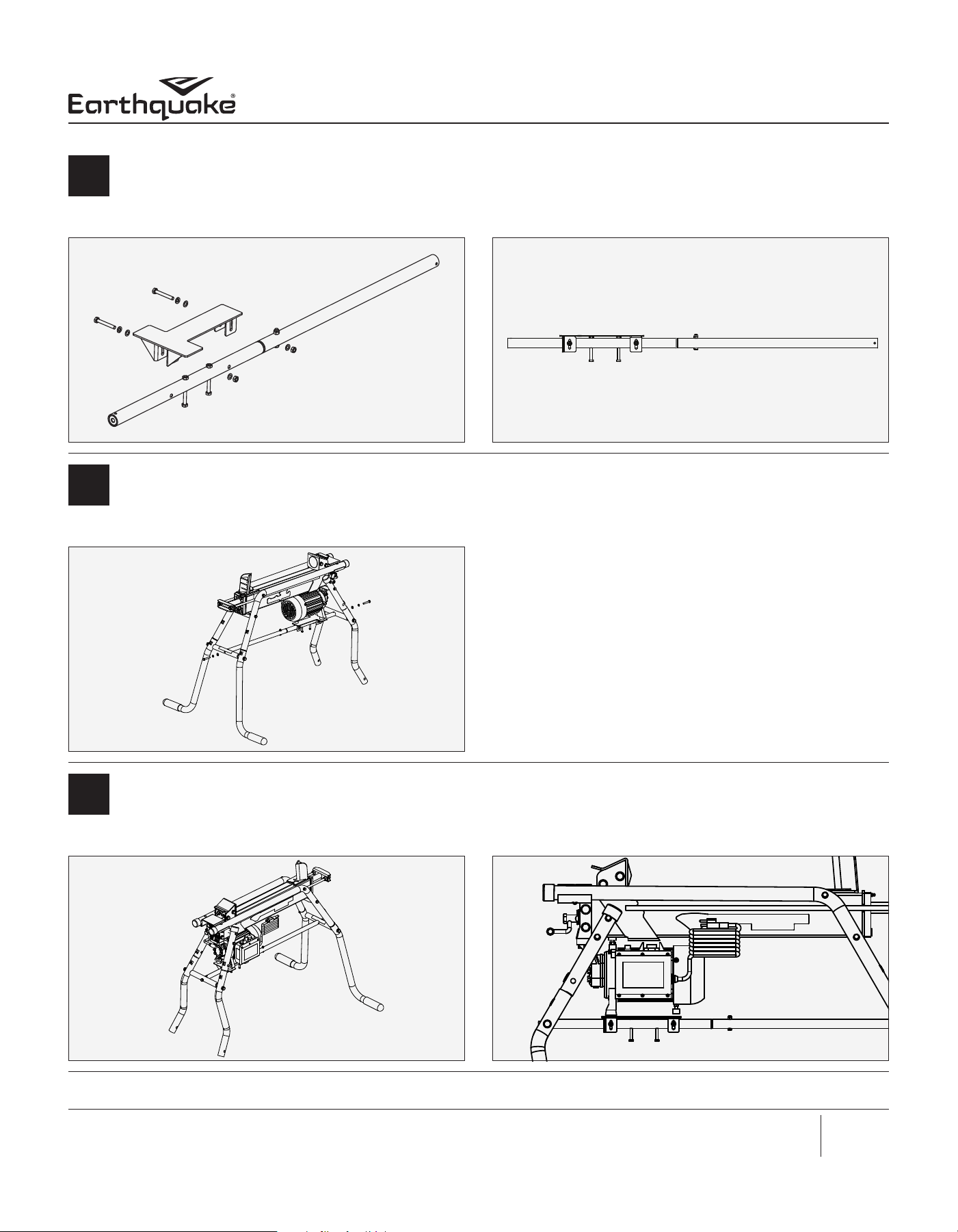
Attach the motor support (8) to the central rod (5) using M6 bolt (13), M6 at washer (19), M6 spring lock washer (21), and
M6 nut (15), as shown in gures 13 and 14. The hardware must be fastened such that the height of the motor support can
be adjusted at a later stage.
7
Fig. 14Fig. 13
Install the central rod (5 & 23) to the cross beams (6 & 7) using the M8 bolts (12), M8 at washer (18) and M8 spring lock
washer (20).
8
Fig. 15
After attaching the central rod to the legs, all hardware shall be tightened using appropriate size wrenches. See gure 16. The
height of the motor support bracket (8) must now be adjusted, such that the motor rests on the upper motor support. See
gure 17.
9
Fig. 17Fig. 16

8 Get parts online at www.getearthquake.com or Call 800-345-6007 M-F 8-4:30 CST
Assembly Instructions
5-TON ELECTRIC LOG SPLITTER STAND AND TRAY
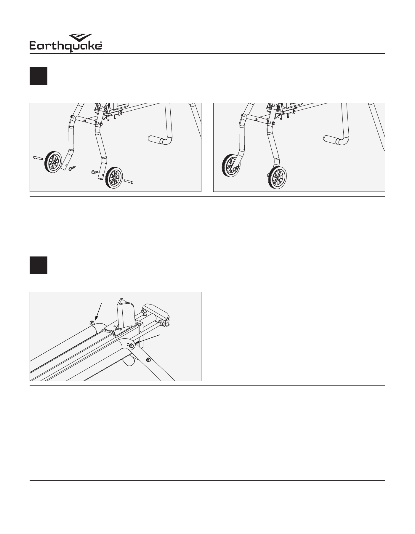
Install the wheels using the pre-assembled wheel and axle (9) and hairpin (22). Refer to gures 18 and 19.
10
Fig. 19Fig. 18
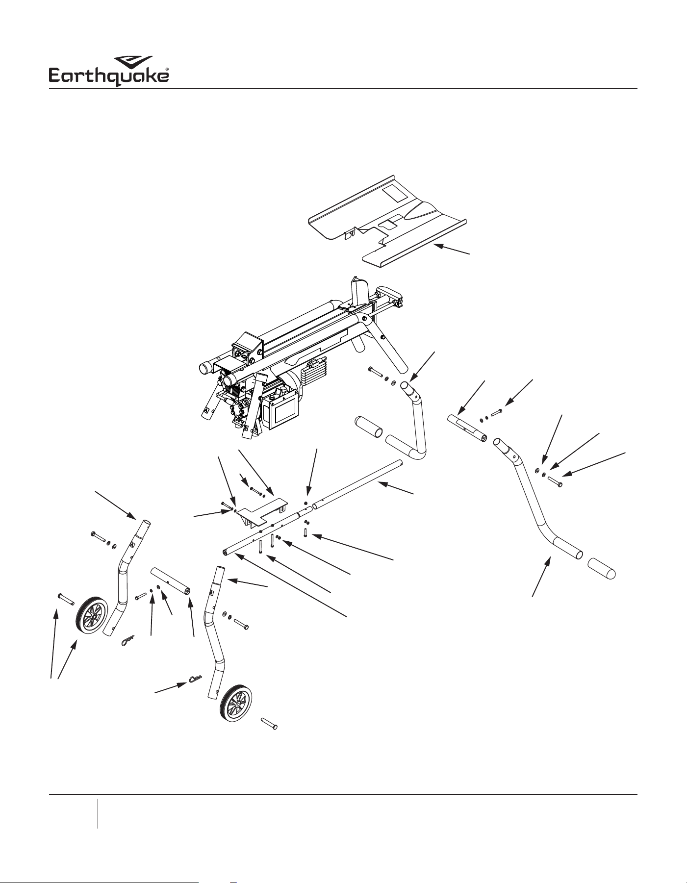
Log Tray Assembly Instructions:
Using a 14mm wrench, loosen the bolts shown in gure 1.
1
Fig. 1
9
Get parts online at www.getearthquake.com or Call 800-345-6007 M-F 8-4:30 CST
Assembly Instructions
5-TON ELECTRIC LOG SPLITTER STAND AND TRAY
There should be about a 1/2” space between the head of the bolt and the leg. Refer to gure 2.
2
1/2”
Fig. 2
Drop down the tray as shown in gure 3 such that the bolt slides through the slot on the bent tabs of the tray. Refer to
gures 3 and 4.
3
Fig. 4Fig. 3
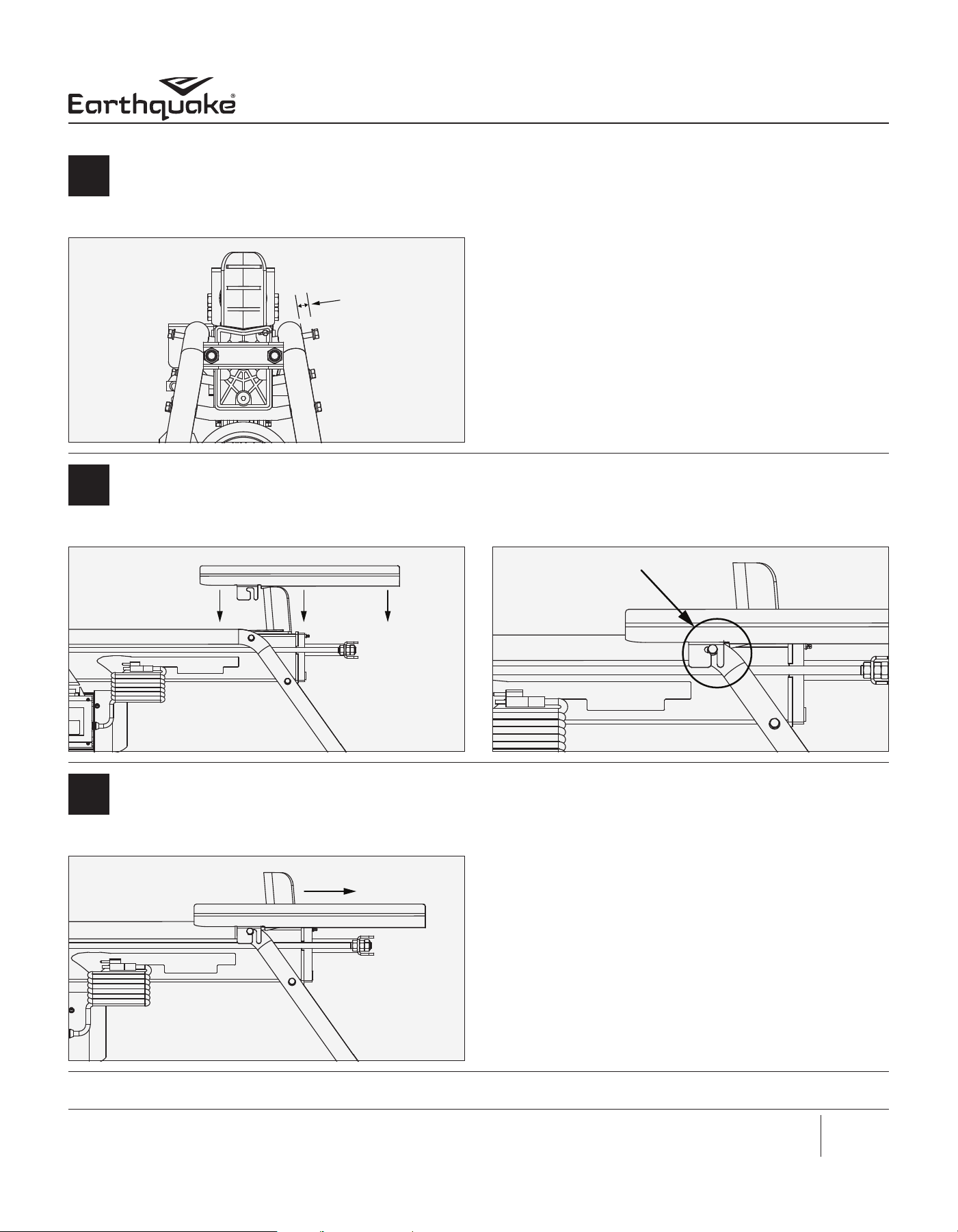
Pull back the tray away from the push block so that the bolts bottom out in the end of the slot. Tighten the bolt using the
14mm wrench.
4
Fig. 5

10 Get parts online at www.getearthquake.com or Call 800-345-6007 M-F 8-4:30 CST
Assembly Instructions
5-TON ELECTRIC LOG SPLITTER STAND AND TRAY
NOTES:

11
Get parts online at www.getearthquake.com or Call 800-345-6007 M-F 8-4:30 CST
Assembly Instructions
5-TON ELECTRIC LOG SPLITTER STAND AND TRAY
NOTES:

12 Pièces détachées en ligne à www.getearthquake.com ou composer le 800-345-6007 L-V 8h-16h30 HNC
Instructions d’assemblage
PIÈTEMENT ET PLATEAU DE FENDEUSE DE BÛCHES ÉLECTRIQUE 5 TONNES
7
18
20
1
25
6
12
16
17
11
22
21
8
13
19
10
2
3
5
15
24
14
23
9
4

13
Pièces détachées en ligne à www.getearthquake.com ou composer le 800-345-6007 L-V 8h-16h30 HNC
Instructions d’assemblage
PIÈTEMENT ET PLATEAU DE FENDEUSE DE BÛCHES ÉLECTRIQUE 5 TONNES
REPÈRE N° RÉF. DESCRIPTION QTÉ
1 34196 PIED ARRIÈRE GAUCHE DU PIÈTEMENT W500 AVEC AUTOCOLLANT 1
2 34197 PIED ARRIÈRE DROIT DU PIÈTEMENT W500 AVEC AUTOCOLLANT 1
3 34199 PIED AVANT DROIT DU PIÈTEMENT W500 AVEC AUTOCOLLANT 1
4 34198 PIED AVANT GAUCHE DU PIÈTEMENT W500 AVEC AUTOCOLLANT 1
5 34777 WELDMENT TUBE 25.1.5X513.2 MM W/ SPACER 1
6 33734 BARRE DE RACCORDEMENT DE PIEDS DU PIÈTEMENT W500 1
7 33734 BARRE DE RACCORDEMENT DE PIEDS DU PIÈTEMENT W500 1
8 33735 SUPPORT MOTEUR MÉCANOSOUDÉ DU PIÈTEMENT W500 1
9 33669 ENSEMBLE ROUE ET AXE W500 1
10 34203 PLATEAU À BÛCHE DU W500 AVEC AUTOCOLLANT 1
11 W1265V0902 VIS M10X1,5X70 MM HHCS GR8.8 ZN P-T 4
12 21718 VIS M8X1,25X50 MM HHCS GR8.8 ZN F-T 2
13 33742 VIS M6X1,0X45 MM HHCS GR8.8 ZN F-T 2
14 331059 VIS M6X1,0X60 MM HH GR8.8 ZN F-T 2
15 31948 ÉCROU M6X1X4,2 MM H GR8.8 ZN 2
16 W1200126 RONDELLE M10X21,25X1,33 MM GR8.8 ZN 4
17 W1200119 RONDELLE M10X18,1X2 MM SPRLK ZN 4
18 20143 RONDELLE M8X16X1,5 MM GR8.8 ZN 2
19 W1200117 RONDELLE M6X12X1,00 MM GR8.8 ZN 4
20 32569 RONDELLE M8X1,25X2,1 MM SPRLK GR8.8 ZN 2
21 W1200116 RONDELLE M6X11,8X1,5 MM SPRLK GR8.8 ZN 2
22 46134 GOUPILLE EN ÉPINGLE 0,148 DIA. X 0,75 D.E. ARBRE 2
23 34778 WELDMENT TUBE 25.1.5X513.2 MM SWEDGE END W/ SPACER 1
24 18104 BOLT M6X1.0X35 MM HHCS GR8.8 ZN F-T 1
25 W1265V0913 NUT M6X1.0X8 MM HNYLK CL8 ZN 1
14 Pièces détachées en ligne à www.getearthquake.com ou composer le 800-345-6007 L-V 8h-16h30 HNC
Instructions d’assemblage
PIÈTEMENT ET PLATEAU DE FENDEUSE DE BÛCHES ÉLECTRIQUE 5 TONNES
Montage du piètement:
Ouvrir le sachet de visserie et identier toute la visserie illustrée ci-dessus.
Tailles de clés nécessaires: 10mm, 14mm, 17mm
14 MM Clé
17 MM Clé
10 MM Clé
(16)
M10 x 21.25 MM Washer
Qty 4
(17)
M10 x 18 MM Washer
Qty 4
(18)
M8 x 16 MM Washer
Qty 2
(19)
M6 x 12 MM Washer
Qty 4
(20)
M8 x 1.25 MM Washer
Qty 2
(11)
M10 x 70 MM Bolt
Qty 4
(14)
M6 x 60 MM Bolt
Qty 2
(12)
M8 x 50 MM Bolt
Qty 2
(13)
M6 x 45 MM Bolt
Qty 2
(15)
M6 x 4.2 MM Nut
Qty 2
(25)
M6 x 8 MM Nylock Nut
Qty 1
(21)
M6 x 11.8 MM Washer
Qty 2
(24)
M6 x 35 MM Bolt
Qty 1
15
Pièces détachées en ligne à www.getearthquake.com ou composer le 800-345-6007 L-V 8h-16h30 HNC
Instructions d’assemblage
PIÈTEMENT ET PLATEAU DE FENDEUSE DE BÛCHES ÉLECTRIQUE 5 TONNES
Soulever la fendeuse de bûches par le côté coin et enler les pieds arrière (1 et 2) en s’assurant que les lettres sur autocollants
se correspondent et que les autocollants soient alignés, comme aux gures 2 et 3.
1
Fig. 3Fig. 2
Avec deux des vis M10 (11), rondelles plates M10 (16) et rondelle-frein élastique M10 (17), monter la barre transversale (6)
entre les pieds arrière (1 et 2). Poser la visserie sans la serrer. La barre transversale (6) est identiée par l’autocollant indiquant
un point de levage de la fendeuse de bûches pour le transport.
2
Fig. 5Fig. 4
Soulever le côté pompe et enler les pieds avant (3 et 4) en veillant à aligner les autocollants.
3
Fig. 7Fig. 6

16 Pièces détachées en ligne à www.getearthquake.com ou composer le 800-345-6007 L-V 8h-16h30 HNC
Instructions d’assemblage
PIÈTEMENT ET PLATEAU DE FENDEUSE DE BÛCHES ÉLECTRIQUE 5 TONNES
Avec deux des vis M10 (11), rondelles plates M10 (16) et rondelle-frein élastique M10 (17), monter la barre transversale (7)
entre les pieds avant (3 et 4). Poser la visserie sans la serrer.
4
Fig. 9Fig. 8
Après avoir monté les pieds, observer la machine par le côté. Son apparence doit être semblable à la gure 10.
5
Fig. 10
Attacher les vis M6 (14, 24) et écrou M6 (25) à la barre centrale (5 & 23) comme illustré à la gure 11. À ce stade, les vis ne
doivent pas dépasser des écrous, comme illustré à la gure 12.
6
Fig. 12Fig. 11

17
Pièces détachées en ligne à www.getearthquake.com ou composer le 800-345-6007 L-V 8h-16h30 HNC
Instructions d’assemblage
PIÈTEMENT ET PLATEAU DE FENDEUSE DE BÛCHES ÉLECTRIQUE 5 TONNES
Attacher le support de moteur (8) à la barre centrale (5) avec les vis M6 (13), rondelles plates M6 (19), rondelles-freins
élastiques M6 (21) et écrous M6 (15), comme illustré aux gures 13 et 14. La visserie doit être posée de telle manière que la
hauteur du support de moteur puisse être ajustée ultérieurement.
7
Attacher la barre centrale (5 & 23) aux barres transversale (6 et 7) avec les vis M8 (12), rondelles plates M8 (18) et rondelles-
freins élastiques M8 (20).
8
Après avoir attaché la barre centrale aux pieds, serrer toute la visserie à l’aide de clés de taille correspondante. Voir gure 16.
La hauteur de l’étrier de support du moteur (8) doit à présent être ajustée de telle manière que le moteur repose sur le dessus
du support de moteur. Voir gure 17.
9
Fig. 14Fig. 13
Fig. 15
Fig. 17Fig. 16

18 Pièces détachées en ligne à www.getearthquake.com ou composer le 800-345-6007 L-V 8h-16h30 HNC
Instructions d’assemblage
PIÈTEMENT ET PLATEAU DE FENDEUSE DE BÛCHES ÉLECTRIQUE 5 TONNES
Monter les ensembles roue et axe préassemblés (9) et épingle à cheveux (22). Voir les gures 18 et 19.
10
Fig. 19Fig. 18
Instructions d’assemblage du plateau à bûches:
Avec une clé de 14mm, desserrer les vis illustrées à la gure 1.
1
Fig. 1

19
Pièces détachées en ligne à www.getearthquake.com ou composer le 800-345-6007 L-V 8h-16h30 HNC
Instructions d’assemblage
PIÈTEMENT ET PLATEAU DE FENDEUSE DE BÛCHES ÉLECTRIQUE 5 TONNES
Il doit y avoir un espacement d’environ 13mm (1/2po) entre la tête de la vis et le pied. Voir la gure 2.
2
1/2”
Fig. 2
Abaisser le plateau comme illustré à la gure 3 de manière à engager la vis dans l’encoche des pattes pliées du plateau. Voir
les gures 3 et 4.
3
Fig. 4Fig. 3
Tirer le plateau vers l’arrière de manière à amener le vis jusqu’au fond de leur encoche. Serrer les vis à l’aide de la clé de 14mm.
4
Fig. 5

20 Obtenga piezas en línea en www.getearthquake.com o llame al 800-345-6007 M-F 8-4:30 CST
Instrucciones de montaje
SOPORTE Y BANDEJA DEL PARTIDOR DE LEÑA ELÉCTRICO DE 5 TONELADAS
7
18
20
1
25
6
12
16
17
11
22
21
8
13
19
10
2
3
5
15
24
14
23
9
4

21
Obtenga piezas en línea en www.getearthquake.com o llame al 800-345-6007 M-F 8-4:30 CST
Instrucciones de montaje
SOPORTE Y BANDEJA DEL PARTIDOR DE LEÑA ELÉCTRICO DE 5 TONELADAS
N.º DE ELEMENTO N.º DE PIEZA DESCRIPCIÓN CANT.
1 34196 PATA TRASERA IZQUIERDA DEL SOPORTE W500 CON CALCOMANÍA 1
2 34197 PATA TRASERA DERECHA DEL SOPORTE W500 CON CALCOMANÍA 1
3 34199 PATA DELANTERA DERECHA DEL SOPORTE W500 CON CALCOMANÍA 1
4 34198 PATA DELANTERA IZQUIERDA DEL SOPORTE W500 CON CALCOMANÍA 1
5 34777 WELDMENT TUBE 25.1.5X513.2 MM W/ SPACER 1
6 33734
CONJUNTO SOLDADO DE VARILLA DE CONEXIÓN DE PATAS DEL
SOPORTE W500
1
7 33734
CONJUNTO SOLDADO DE VARILLA DE CONEXIÓN DE PATAS DEL
SOPORTE W500
1
8 33735 CONJUNTO SOLDADO DE SOPORTE DEL MOTOR DEL SOPORTE W500 1
9 33669 CONJUNTO DE EJE DE RUEDA W500 1
10 34203 BANDEJA DE LEÑOS W500 CON CALCOMANÍA 1
11 W1265V0902 PERNO M10X1.5X70MM HHCS GR8.8 ZINC, ROSCA PARA TUBOS 4
12 21718 PERNO M8X1.25X50MM HHCS GR8.8 ZINC, ROSCA FINA 2
13 33742 PERNO M6X1.0X45MM HHCS GR8.8 ZINC, ROSCA FINA 2
14 331059 PERNO M6X1.0X60MM HHCS GR8.8 ZINC, ROSCA FINA 2
15 31948 TUERCA M6X1X4.2MM GR8.8 ZINC 2
16 W1200126 ARANDELA M10X21.25X1.33MM GR8.8 ZINC 4
17 W1200119 ARANDELA M10X18.1X2MM SPRLK ZINC 4
18 20143 ARANDELA M8X16X1.5MM GR8.8 ZINC 2
19 W1200117 ARANDELA M6X12X1.00MM GR8.8 ZINC 4
20 32569 ARANDELA M8X1.25X2.1MM SPRLK GR8.8 ZINC 2
21 W1200116 ARANDELA M6X11.8X1.5MM SPRLK GR8.8 ZINC 2
22 46134 PASADOR DE HORQUILLA 0.148 DIÁM. X 0.75 DIÁM. EXT. EJE 2
23 34778 WELDMENT TUBE 25.1.5X513.2 MM SWEDGE END W/ SPACER 1
24 18104 BOLT M6X1.0X35 MM HHCS GR8.8 ZN F-T 1
25 W1265V0913 NUT M6X1.0X8 MM HNYLK CL8 ZN 1

22 Obtenga piezas en línea en www.getearthquake.com o llame al 800-345-6007 M-F 8-4:30 CST
Instrucciones de montaje
SOPORTE Y BANDEJA DEL PARTIDOR DE LEÑA ELÉCTRICO DE 5 TONELADAS
Instalación del soporte:
Abra la bolsa de piezas metálicas e identique todas las que se muestran arriba.
Tamaños de llave necesarios: 10mm, 14mm, 17mm
14 MM Llave
17 MM Llave
10 MM Llave
(16)
M10 x 21.25 MM Washer
Qty 4
(17)
M10 x 18 MM Washer
Qty 4
(18)
M8 x 16 MM Washer
Qty 2
(19)
M6 x 12 MM Washer
Qty 4
(20)
M8 x 1.25 MM Washer
Qty 2
(11)
M10 x 70 MM Bolt
Qty 4
(14)
M6 x 60 MM Bolt
Qty 2
(12)
M8 x 50 MM Bolt
Qty 2
(13)
M6 x 45 MM Bolt
Qty 2
(15)
M6 x 4.2 MM Nut
Qty 2
(25)
M6 x 8 MM Nylock Nut
Qty 1
(21)
M6 x 11.8 MM Washer
Qty 2
(24)
M6 x 35 MM Bolt
Qty 1

23
Obtenga piezas en línea en www.getearthquake.com o llame al 800-345-6007 M-F 8-4:30 CST
Instrucciones de montaje
SOPORTE Y BANDEJA DEL PARTIDOR DE LEÑA ELÉCTRICO DE 5 TONELADAS
Levante el partidor de leña desde la cuña e inserte las patas traseras (1 y 2); asegúrese de que las letras de las calcomanías
coincidan y que las calcomanías se alineen como en las guras 2 y 3.
1
Fig. 3Fig. 2
Con dos de los pernos M10 (11), la arandela plana M10 (16) y la arandela elástica de bloqueo M10 (17), instale la viga
transversal (6) entre las patas traseras (1 y 2). Las piezas metálicas se deben instalar sueltas. La viga transversal (6) se identica
con la calcomanía que hace referencia a una ubicación de elevación para el transporte del partidor de leña.
2
Fig. 5Fig. 4
Levante el extremo de la bomba e inserte las patas delanteras (3 y 4) y asegúrese de que las calcomanías estén alineadas.
3
Fig. 7Fig. 6
24 Obtenga piezas en línea en www.getearthquake.com o llame al 800-345-6007 M-F 8-4:30 CST
Instrucciones de montaje
SOPORTE Y BANDEJA DEL PARTIDOR DE LEÑA ELÉCTRICO DE 5 TONELADAS
Con dos de los pernos M10 (11), arandelas planas M10 (16) y la arandela elástica de bloqueo M10 (17), instale la viga
transversal (7) entre las patas delanteras (3 y 4). Las piezas metálicas se deben instalar sueltas.
4
Fig. 9Fig. 8
Después de instalar las patas, observe la unidad desde un lado. Debería verse similar a la gura 10.
5
Fig. 10
Con los pernos M6 (14, 24) y tuerca M6 (25), je a la varilla central (5 & 23) como se muestra en la gura 11. En esta etapa,
los pernos no deben sobresalir de la tuerca, como se muestra en la gura 12.
6
Fig. 12Fig. 11
25
Obtenga piezas en línea en www.getearthquake.com o llame al 800-345-6007 M-F 8-4:30 CST
Instrucciones de montaje
SOPORTE Y BANDEJA DEL PARTIDOR DE LEÑA ELÉCTRICO DE 5 TONELADAS
Instale el soporte del motor (8) en la varilla central (5) con el perno M6 (13), la arandela plana M6 (19), la arandela elástica de
bloqueo M6 (21) y la tuerca M6 (15), como se muestra en las guras 13 y 14. Las piezas metálicas se deben jar de manera
que la altura del soporte del motor se pueda ajustar en una etapa posterior.
7
Instale la varilla central (5 & 23) en las vigas transversales (6 y 7) con los pernos M8 (12), la arandela plana M8 (18) y la
arandela elástica de bloqueo M8 (20).
8
Después de conectar la varilla central con las patas, se deben apretar todas las piezas metálicas con las llaves del tamaño
correcto. Consulte la gura 16. Ahora se puede ajustar la altura del soporte del motor (8), de manera que el motor se apoye
en el soporte superior del motor. Consulte la gura 17.
9
Fig. 14Fig. 13
Fig. 15
Fig. 17Fig. 16
26 Obtenga piezas en línea en www.getearthquake.com o llame al 800-345-6007 M-F 8-4:30 CST
Instrucciones de montaje
SOPORTE Y BANDEJA DEL PARTIDOR DE LEÑA ELÉCTRICO DE 5 TONELADAS
Instale las ruedas con la rueda y eje montados previamente (9) y pasador de chaveta (22). Consulte las guras 18 y 19.
10
Fig. 19Fig. 18
Instrucciones de montaje de la bandeja de leños:
Con una llave de 14mm, suelte los pernos que se muestran en la gura 1.
1
Fig. 1

27
Obtenga piezas en línea en www.getearthquake.com o llame al 800-345-6007 M-F 8-4:30 CST
Instrucciones de montaje
SOPORTE Y BANDEJA DEL PARTIDOR DE LEÑA ELÉCTRICO DE 5 TONELADAS
Debe haber un espacio de aproximadamente 1/2" entre la cabeza del perno y la pata. Consulte la gura 2.
2
1/2”
Fig. 2
Deje caer la bandeja como se muestra en la gura 3, de modo que el perno se deslice a través de la ranura en las lengüetas
dobladas de la bandeja. Consulte las guras 3 y 4.
3
Fig. 4Fig. 3
Mueva la bandeja en dirección contraria al bloque de empuje, de modo que los pernos sobresalgan en el extremo de la
ranura. Apriete el perno con la llave de 14mm.
4
Fig. 5

ARDISAM, INC.
1730 Industrial Avenue
PO Box 666
Cumberland, WI 54829
Phone: (800) 345-6007
Téléphone: (800) 345-6007
Teléfono: (800) 345-6007
Fax: (715) 822-2124
Télécopieur: (715) 822-2124
Fax: (715) 822-2124
www.getearthquake.com
