

OPERATOR'S MANUAL
MODEL #201519
37 TON FULL BEAM LOg SPLiTTER
Champion Power Equipment, Inc.
or visit championpowerequipment.com
READ AND SAVE THiS MANUAL. This manual contains important safety precautions which should be read and understood before operating the product. Failure to
do so could result in serious injury. This manual should remain with the product.
Specifications, descriptions and illustrations in this manual are as accurate as known at the time of publication, but are subject to change without notice.
5296-M-OP REV 20240906
EN
ACTIVATE YOUR WARRANTY
by registering your product:
championpowere quipment.com
SERIAL NO.

201519 - 37 TON FULL BEAM LOg SPLiTTER
TABLE OF CONTENTS
2
TABLE OF CONTENTS
introduction ................................................... 3
Safety Definitions
..........................................3
important Safety instructions
.......................4
Fuel Safety .........................................................6
Training Instructions ...............................................7
Preparation .........................................................7
Operation ...........................................................8
Maintenance ........................................................ 8
Safety and Dataplate Labels .......................................9
Safety Symbols ................................................... 10
Operation Symbols ............................................... 12
Quickstart Label Symbols........................................ 12
Controls and Features ................................. 13
Log Splitter ....................................................... 13
Engine ............................................................ 14
Parts Included .................................................... 15
Assembly ..................................................... 16
Open Shipping Crate ............................................. 16
1) Install the Fenders ............................................. 16
2) Install the Wheels ............................................. 16
3) Install the Tow Bar ............................................ 16
4) Install the Beam ............................................... 17
5) Install the Engine .............................................. 17
6) Install the Hose and Hydraulic Filter .......................... 17
7) Install the Log Catchers ....................................... 18
Add Engine Oil .................................................... 19
Add Fuel .......................................................... 20
Add Hydraulic Oil ................................................. 21
Before Each Use Inspect the Log Splitter ....................... 22
Changing Beam from Horizontal to Vertical Orientation ........ 22
Towing Log Splitter Safety ....................................... 23
Log Splitter Location ............................................. 23
Operation .....................................................24
Starting the Engine ............................................... 24
Stopping the Engine .............................................. 25
Log Splitter Operation ............................................ 26
Operation at High Altitude ....................................... 26
Maintenance ................................................27
Cleaning the Log splitter ......................................... 27
Changing the Engine Oil ......................................... 27
Cleaning and Adjusting the Spark Plug(s) ....................... 28
Cleaning the Air Filter ............................................ 28
Changing the Hydraulic Oil ....................................... 28
Maintenance Schedule ........................................... 29
Storage ........................................................30
Log Splitter Storage .............................................. 30
Engine Stored for Less than 30 Days ........................... 30
Engines Stored for Over 30 Days ................................ 30
Specifications ..............................................31
Log Splitter Specifications ....................................... 31
Engine Specifications ............................................ 31
Oil Specifications ................................................. 31
Hydraulic Oil System ............................................. 31
Fuel Specifications ............................................... 31
Spark Plug Specifications ........................................ 31
Valve Specifications .............................................. 31
Important Message About Temperature......................... 31
Troubleshooting ........................................... 32
FOR PARTS BREAKDOWN
Search by model number at
championpowerequipment.com

201519 - 37 TON FULL BEAM LOg SPLiTTER
iNTRODUCTiON
3
iNTRODUCTiON
Congratulations on your purchase of a Champion Power Equipment
(CPE) product. CPE designs, builds, and supports all of our
products to strict specifications and guidelines. With proper
product knowledge, safe use, and regular maintenance, this
product should bring years of satisfying service.
Every effort has been made to ensure the accuracy and
completeness of the information in this manual at the time of
publication, and we reserve the right to change, alter and/or
improve the product and this document at any time without prior
notice.
Since CPE highly values how our products are designed,
manufactured, operated and are serviced, and also highly value
your safety and the safety of others, we would like you to take the
time to review this product manual and other product materials
thoroughly and be fully aware and knowledgeable of the assembly,
operation, dangers and maintenance of the product before use.
Fully familiarize yourself, and make sure others who plan on
operating the product fully familiarize themselves too, with the
proper safety and operation procedures before each use. Please
always exercise common sense and always err on the side
of caution when operating the product to ensure no accident,
property damage, or injury occurs. We want you to continue to use
and be satisfied with your CPE product for years to come.
When contacting CPE about parts and/or service, you will need to
supply the complete model and serial numbers of your product.
Transcribe the information found on your product’s nameplate
label to the table below
CPE TEChniCal SuPPorT TEam
1-877-338-0999
moDEl numBEr
201519
SErial numBEr
DaTE oF PurChaSE
PurChaSE loCaTion
SAFETY DEFiNiTiONS
The purpose of safety symbols is to attract your attention to
possible dangers. The safety symbols, and their explanations,
deserve your careful attention and understanding. The safety
warnings do not by themselves eliminate any danger.
The instructions or warnings they give are not substitutes for
proper accident prevention measures.
DANgER
DANGER indicates a hazardous situation which,if not avoided,
will result in death or serious injury.
WARNiNg
WARNING indicates a hazardous situation which, if not
avoided, could result in death or serious injury.
CAUTiON
CAUTION indicates a hazardous situation which, if not avoided,
could result in minor or moderate injury.
NOTiCE
NOTICE indicates information considered important, but not
hazard-related (e.g., messages relating to property damage).

201519 - 37 TON FULL BEAM LOg SPLiTTER
iMPORTANT SAFETY iNSTRUCTiONS
4
iMPORTANT SAFETY iNSTRUCTiONS
WARNiNg
Cancer and Reproductive Harm – www.P65Warnings.ca.gov
DANgER
Engine exhaust contains carbon monoxide, a colorless,
odorless, poison gas. Breathing carbon monoxide will cause
nausea, dizziness, fainting or death.
If you start to feel dizzy or weak, move to fresh air immediately.
operate log splitter onlY outdoors in a well ventilated
area.
DO NOT operate the log splitter inside any building, including
garages, basements, crawlspaces, sheds, or enclosure.
DO NOT allow exhaust fumes to enter a confined area through
windows, doors, vents or other openings.
DANgER
Using an engine indoors Can Kill You in minuTES. Engine
exhaust contains carbon monoxide. This is a poison you cannot
see or smell.
nEVEr use inside a home or garage, EVEn iF doors and
windows are open.
alWaYS use ouTSiDE and far away from windows, doors,
and vents.
WARNiNg
Although the log splitter contains a spark arrester, maintain
a minimum distance of 5 ft. (1.5 m) from dry vegetation to
prevent fires.
WARNiNg
Sparks can result in fire or electrical shock.
When servicing the engine:
Disconnect the spark plug wire and place it where it cannot
contact the plug.
DO NOT check for spark with the plug removed.
Use only approved spark plug testers.
WARNiNg
Running engines produce heat. Severe burns can occur on
contact. Combustible material can catch fire on contact.
DO NOT touch hot surfaces.
Avoid contact with hot exhaust gases.
Allow equipment to cool before touching.
Maintain at least 3 ft. (91.4 cm) of clearance on all sides to
ensure adequate cooling.
WARNiNg
Crush Hazard
Wedge can cut through skin and break bones. Keep all limbs
away from wedge and endplate.
WARNiNg
Projectile Hazard
Pieces of log may be ejected from the log splitter while
operating. Always wear ANSI approved safety glasses when
operating. Be alert.
WARNiNg
Keep operator work zone clear of debris while working to
ensure safe footing.
DANgER
Skin Injection Hazard.
Hydraulic oil escaping under high pressure can penetrate skin
and cause serious bodily injury. In the event that hydraulic oil
may penetrate the skin and to avoid serious infections such as
gangrene, seek proper medical attention immediately.
WARNiNg
Always make sure all hydraulic oil connections are tightly
secured and hydraulic hoses are in good condition, no cuts,
tears, or damage before applying pressure to the system.

201519 - 37 TON FULL BEAM LOg SPLiTTER
iMPORTANT SAFETY iNSTRUCTiONS
5
WARNiNg
Always keep hands and body parts away from nozzles or
pinholes that could eject hydraulic oil under high pressure in
the event of an oil leak.
NEVER use bare hands to search for leaks. Leaks can be
detected by using cardboard, paper or scrap wood over the
suspected area.
WARNiNg
Towing Hazard
Always check with your local municipality, state or provincial
regulations regarding towing, lights and licensing before
towing your log splitter on public roads.
BEFORE towing, review all safety warnings in your towing
vehicle manual. Drive safely. Be aware of the added length of
the log splitter.
NEVER ride or transport cargo on the log splitter.
DO NOT exceed the maximum 45 MPH (72 KM/H) towing
speed.
WARNiNg
Before removing the pin installed on the front support leg,
make sure the hitch is installed onto the vehicle. Releasing
the pin before will cause support leg to slide up and possibly
cause injury.
WARNiNg
Rapid retraction of the starter cord will pull hand and arm
towards the engine faster than you can let go. Broken bones,
fractures, bruises or sprains could result.
Unintentional startup can result in entanglement, traumatic
amputation or laceration.
When starting engine, pull the starter cord slowly until
resistance is felt and then pull rapidly to avoid kickback.
CAUTiON
Parts of the hydraulic circuit (cylinder, pump, valve-body,
hoses) can become very hot during operation.
WARNiNg
Improper treatment or use of the log splitter can damage it,
shorten its life and void your warranty.
ALWAYS use the log splitter for its intended use.
ALWAYS operate only on level surfaces.
DO NOT expose log splitter to excessive moisture, dust,
or dirt.
DO NOT allow any material to block the cooling slots.
Do noT use the engine if:
– Equipment sparks, smokes or emits flames
– Equipment vibrates excessively

201519 - 37 TON FULL BEAM LOg SPLiTTER
iMPORTANT SAFETY iNSTRUCTiONS
6
Fuel Safety
DANgER
GaSolinE anD GaSolinE VaPorS arE hiGhlY
FlammaBlE anD EXPloSiVE.
Fire or explosion can cause severe burns or death.
Gasoline and gasoline vapors:
– Gasoline vapors are highly flammable and explosive.
– Gasoline vapors can cause a fire or explosion if ignited.
– Gasoline is a liquid fuel and the resulting gasoline vapors can
ignite and cause a fire or explosion.
– Gasoline is a skin irritant and needs to be cleaned up
immediately if spilled on skin or clothes.
– Gasoline has a distinctive odor, this will help detect potential
leaks quickly.
– In any petroleum gas fire, flames should not be extinguished
unless by doing so the fuel supply valve can be turned OFF.
This is because if a fire is extinguished and a supply of fuel is
not turned OFF, then an explosion hazard could be created.
– Gasoline vapors expand and contract with ambient
temperatures. Never fill the gasoline tank past the red FULL
indicator on the fuel filter, as gasoline vapors needs room to
expand if temperatures rise.
WARNiNg
When adding or removing gasoline:
Do not light or smoke cigarettes.
Always stop the engine and allow to cool for a minimum of two
minutes before refueling.
Always loosen gasoline cap slowly to release vapor pressure
and to keep fuel from escaping around the gasoline cap.
Always replace and tighten the gasoline cap securely after
fueling.
Never remove the gasoline cap or add gasoline while the
engine is running or when the engine is hot.
Always fill or drain gasoline outdoors in a well-ventilated area.
Do not pump gasoline directly into the log splitter at the gas
station.
Always store gasoline in an EPA/CARB compliant container or
to transfer the gasoline to the log splitter.
Do not overfill the gasoline tank.
Always keep gasoline away from sparks, open flames, pilot
lights, heat and other sources of ignition.
WARNiNg
When starting the log splitter:
Do not attempt to start a damaged log splitter.
Always check that the gasoline cap, air filter, spark plug, fuel
lines and exhaust system are properly in place.
Always allow spilled gasoline to evaporate fully before
attempting to start the engine.
Always be certain that the log splitter is resting firmly on level
ground.
WARNiNg
When operating the log splitter:
Do not move or tip the log splitter during operation.
WARNiNg
When transporting or servicing the log splitter:
Always check that the fuel valve is in the OFF position and the
gasoline tank is empty.
Disconnect the spark plug wire.
WARNiNg
When storing the log splitter:
Store away from sparks, open flames, pilot lights, heat and
other sources of ignition.
Do not store log splitter or gasoline near furnaces, water
heaters, or any other appliances that produce heat or have
automatic ignitions.
DANgER
Never place a gasoline container, gasoline tank, or any
combustible material in the path of the exhaust stream during
operation of the engine.
WARNiNg
Never use a gasoline container, gasoline tank, or any other fuel
item that is broken, cut, torn or damaged.

201519 - 37 TON FULL BEAM LOg SPLiTTER
iMPORTANT SAFETY iNSTRUCTiONS
7
Training instructions
CAUTiON
1. Read the Operator’s Manual completely before attempting
to use this log splitter.
2. Do not allow anyone to operate your log splitter who has
not read the Operator’s Manual or has not been instructed
on the safe use of the log splitter.
3. Never allow children or untrained adults to operate this
machine.
4. Accidents occur when more than one (1) person operates
the log splitter. If a helper is assisting in loading logs to
be split, never actuate controls until helper is clear of the
area.
5. Never transport cargo on the log splitter or ride on the
machine.
6. High fluid pressures develop in hydraulic log splitters.
Pressurized hydraulic fluid escaping through a pin hole
opening can puncture skin and cause severe infections or
blood poisoning. Therefore, these instructions should be
followed at all times.
– Do not operate the unit with frayed, kinked, cracked
or damaged hoses, fittings, or tubing.
– Stop the engine and relieve hydraulic system pressure
before changing or adjusting fittings, hoses, tubing, or
other system components.
– Do not adjust the pressure settings of the pump or
valve.
– Do not check for leaks with your hand. Leaks can
be detected by passing cardboard or wood over the
suspected area. Look for discoloration. If injured by
escaping fluid, see a doctor at once. Serious infection
or reaction can develop if proper medical treatment is
not administered immediately.
7. Keep the operator zone and adjacent area clear for safe,
secure footing.
8. Your log splitter is equipped with an internal-combustion
engine and is not intended for use near any unapproved
regulated and controlled forest, brush, or grass covered
land. Always check with your local municipality, state and
federal regulations prior to use.
9. Log splitters should be used only for splitting wood.
Preparation
CAUTiON
1. Be thoroughly familiar with all controls and with proper
use of the equipment.
2. Safety Gear:
– Always wear safety shoes or heavy boots when
operating the machine.
– Always wear safety glasses or goggles when
operating the machine.
– Never wear jewelry or loose-fitting clothing that might
become entangled in moving or rotating parts of the
machine.
3. Make sure the log splitter is on a level surface. Block tires
and ensure support leg is secure to prevent unintended
movement of the log splitter during operation.
– Always operate the splitter from the manufacturer’s
indicated operator zone.
4. Logs to be split on ram-type units should be cut as
squarely as possible.

201519 - 37 TON FULL BEAM LOg SPLiTTER
iMPORTANT SAFETY iNSTRUCTiONS
8
Operation
CAUTiON
1. Before starting this log splitter, review all safety
instructions. Failure to follow these instructions may
result in serious injury to the operator or bystanders.
2. Be sure to confirm all hose clamp connections are tight
before each use. It is possible for clamp connections to
vibrate loose over time.
3. Never leave the machine unattended with the power
source operating.
4. Never operate the machine when under the influence of
alcohol, drugs or medication.
5. The machine owner should instruct all operators in safe
log splitter operation.
6. Always operate the log splitter with all safety equipment
in place and all controls properly adjusted for safe
operation.
7. Always operate the log splitter at manufacturer’s
recommended speed.
8. Always keep hands and feet clear of moving parts.
9. When loading a ram-type log splitter, place your hands on
the sides of the log, not the ends. Never place your hands
or any part of your body between a log and any part of the
log splitter.
10. On ram-type log splitters, never attempt to split more
than one (1) log at a time unless the ram has been fully
extended and a second log is needed to complete the
separation of the first log.
11. On ram-type log splitters on which the logs are not cut
square, the longest portion of the log should be rotated
down and the most square end placed against the ram.
12. Always split logs with the grain of the wood.
13. Never split perpendicular to the grain of the wood.
14. Use only your hand to operate the log splitter controls.
15. Never add fuel to a running or hot engine.
16. Always turn the engine off and wait a minimum of 2
minutes to cool engine before removing gasoline cap prior
to refueling.
Maintenance
CAUTiON
1. Always shut off the power source while repairing or
adjusting the log splitter except as recommended by the
manufacturer.
2. Clean debris and chaff from the engine cylinder, cylinder
head fins, recoil starter cover, and muffler areas. The
engine is equipped with a spark arrestor muffler, clean
and inspect it regularly (follow manufacturer’s service
instructions). Replace, if damaged.
3. Check to be sure all nuts and bolts are tight to assure
the equipment is in safe working condition before next
operation.
201519 - 37 TON FULL BEAM LOg SPLiTTER
iMPORTANT SAFETY iNSTRUCTiONS
9
Top
Back
A
B
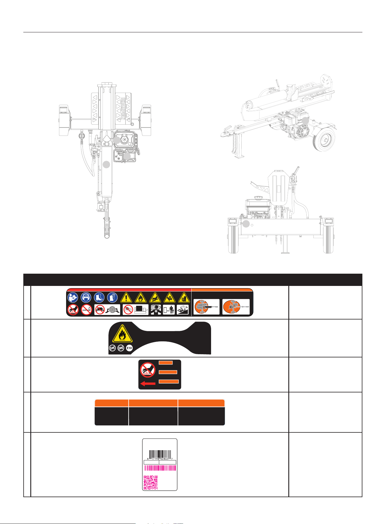
Safety and Dataplate Labels
These labels warn you of potential hazards that can cause serious injury. Read them carefully.
If a label comes off or becomes hard to read, contact Technical Support Team for possible replacement.
C
laBEl DESCriPTion
a
1117-L-SF-B
DANGER PELIGRO WARNING ADVERTENCIA AVERTISSEMENT DANGER
HORIZONTAL WORK ZONE
AREA DE TRABAJO HORIZONTAL
ZONE DE TRAVAIL HORIZONTALE
K 485 2945 109 30%K
ColorsLPN 1117- L-S F
Rev A
Size 190 x 44 mm
Artwork Notes
3mm corner radius; 2mm safe margin
Revision Changes
-Adde d safe work zone
This art work belongs to Cham pion Power Equipment. T he contents are con fidential and privi leged and shall not be disc losed to or used by or for
outside pa rties withou t the explicit consen t of Champion Power Eq uipment.
VERTICAL WORK ZONE
AREA DE TRABAJO VERTICAL
ZONE DE TRAVAIL VERTICALE
Safety Symbols
B
2018-L-OP-B
ESSENCE SANS PLOM SEULEMENT.
Indice d’octane minimal de
87. Maximum 10 % d'éthanol.
La clasificación mínimo de 87
octano. Máximo de etanol de 10%.
GASOLINA SIN PLOMO SOLAMENTE.UNLEADED FUEL ONLY.
Minimum octane rating of 87.
Maximum 10% ethanol.
K 109 --- --- ---
ColorsLPN 2 018-L-OP
Rev B
Size Special
Artwork Notes
3mm corner radius; 2mm safe margin;
to be printed
on
WHITE
substrate.
Revision Changes
B -Cha nge octan e rating 8 5 to octane r ating 87
(20200409)
This artwork belongs to Champion Power Equipment. The contents are confidential and privileged and shall not be disclosed to or used by or for
outside p arties withou t the explicit conse nt of Champion Power E quipment.
Fuel
C
1966-L-SF-B
DO NOT TOUCH!
Hot surface.
WARNING
¡NO TOCAR!
Superficie caliente.
ADVERTENCIA
AVERTISSEMENT
NE TOUCHEZ PAS!
Surface chaude.
K 485 152 --- ---
ColorsLPN 196 6-L-SF
Rev B
Size 5 9 x 42 mm
Artwork Notes
3mm corner radius; 2mm safe margin;
white t o be
print ed shown in 50% p rocess mag enta
Revision Changes
B: Upda te size to matc h Rota 301cc -- 2 0230915
This art work belongs to Champion Power Equipmen t. The contents are confidential and privileged and shall not be disclose d to or used by or for
outside p arties withou t the explicit conse nt of Champion Power E quipment.
Hot Surface
D
4572-L-SF-B
WARNING ADVERTENCIA AVERTISSEMENT
Before transporting,
ALWAYS check that
the fuel valve is OFF
and fuel tank is empty.
Antes del transporte, compruebe
SIEMPRE que la válvula de
combustible está CERRADA y que el
tanque de combustible está vacío.
Avant le transport, vérifiez
TOUJOURS que le robinet de
carburant est FERMÉ et que le
réservoir de carburant est vide.
152 K --- --- ---
ColorsAPN 4572-L-SF
Rev B
Size 112 x 23 mm
Artwork Notes
2mm corner radius; 2mm safe margin;
to be printed
on
WHITE
substrate.
Revision Changes
B: optimize size (20240424)
This artwork belongs to Champion Power Equipment. The contents are confidential and privileged and shall not be disclosed to or used by or for
outside parties without the explicit consent of Champion Power Equipment.
Fuel valve and gasoline
tank
E
CHAMPION POWER EQUIPMENT, INC.
6370 S PIONEER WAY, UNIT 101
LAS VEGAS, NV 89113
USA / É.-U. • 1-877-338-0999
WWW.CHAMPIONPOWEREQUIPMENT.COM
MADE IN CHINA / FABRIQUÉ EN CHINE
5361-L-PR-A
SERIAL NO.
N° DE SÉRIE
MODEL
MODÈLE
201519
REGISTER TO
ACTIVATE YOUR
WARRANTY
ENREGISTREZ-VOUS POUR
ACTIVEZ VOTRE
GARANTIE
XXXXXXXXXXXX
K --- --- --- ---
ColorsAPN 5361-L-PR
Rev A
Size 51 x 76 mm
Artwork Notes
3mm cor ner radius ; 2mm safe mar gin; to be prin ted
on secu rity subst rate; magen ta text to be fill ed in
durin g time of prod uction
Revision Changes
--
This art work belongs to Cham pion Power Equipment. T he contents are con fidential and privi leged and shall not be disc losed to or used by or for
outside p arties withou t the explicit consen t of Champion Power E quipment.
Dataplate
E
D
Side View

201519 - 37 TON FULL BEAM LOg SPLiTTER
iMPORTANT SAFETY iNSTRUCTiONS
10
Safety Symbols
Some of the following symbols may be used on this product. Please study them and learn their meaning. Proper interpretation of these
symbols will allow you to more safely operate the product.
SYmBol mEaninG
read operator’s manual. To reduce the risk of injury, user must read and understand operator’s
manual before using this product.
Eye and Ear Protection. Always wear safety goggles or safety glasses with side shields, and as
necessary a full face-shield as well as full ear protection when operating this product.
Footwear. Always wear safety shoes or heavy boots when operating the machine.
Gloves. Always wear nonslip, heavy-duty protective gloves when operating this product.
Safety alert. Precautions that involve your safety.
risk of Fire. Fuel and its vapors are extremely flammable and explosive. Fire can cause severe
burns or death. Do not add fuel while the product is operating or still hot.
Skin injection hazard. High pressure hydraulic oil can inject under your skin.
Make sure all fittings are tightly secure before applying pressure. Relieve system
pressure before servicing.
Always keep hands away from the wedge and the ram. Moving parts can crush or cut.

201519 - 37 TON FULL BEAM LOg SPLiTTER
iMPORTANT SAFETY iNSTRUCTiONS
11
SYmBol mEaninG
Always keep feet away from the wedge and the ram. Moving parts can crush or cut.
hot Surface. To reduce the risk of injury or damage, avoid contact with any hot surface
open Flame alert. Fuel and its vapors are extremely flammable and explosive. Keep fuel away
from smoking, open flames, sparks, pilot lights, heat, and other ignition sources.
Hold logs on sides when loading. Keep hands and feet away from cylinder, wedge,
and partially split logs.
Never place hands or any part of the body between a log and any part of the log splitter.
Do not split logs against the grain. Split logs end to end in the direction of the grain only.
Toxic Fumes. The engine exhaust from this product contains chemicals known to the state of
California to cause cancer and birth defects and other reproductive harm.
risk of asphyxiation. This engine emits carbon monoxide, an odorless, colorless poison gas.
Breathing carbon monoxide can cause nausea, fainting or death. Always use in a well ventilated
area.
Clearance. Keep all objects including others at least 10 feet (3m) from this machine.
Only one person should operate the log splitter and load the logs
Never operate on an incline. Make sure the log splitter is on a level surface. Block tires and ensure
support leg is secure to prevent unintended movement of the log splitter during operation.
MAX. 45 MPH (72 km/h)
Do noT exceed the maximum 45 MPH (72 KM/H) towing speed.
Always check all local, state or provincial regulations regarding towing, licensing and lights before
towing your log splitter. Review towing safety warnings in your towing vehicle manual.
Any modifications required to meet these laws are the responsibility of the purchaser.

201519 - 37 TON FULL BEAM LOg SPLiTTER
iMPORTANT SAFETY iNSTRUCTiONS
12
Operation Symbols
Some of the following symbols may be used on this product. Please study them and learn their meaning. Proper interpretation of these
symbols will allow you to more safely operate the product.
SYmBol mEaninG
SToP or oFF
Fuel/Gasoline Valve on/oFF
Choke
run
SYmBol mEaninG
Fuel Gauge: Full
Fuel Gauge: Empty
Quickstart Label Symbols
Some of the following symbols may be used on this product. Please study them and learn their meaning. Proper interpretation of these
symbols will allow you to more safely operate the product.
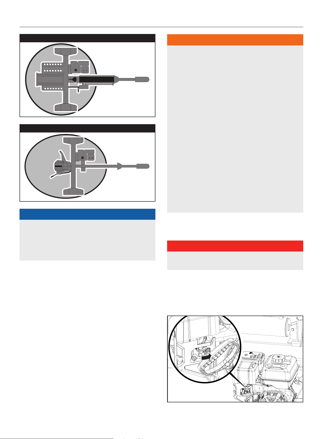
Starting the Engine
DANgER
move log splitter outside and far away from windows,
doors and intake ventilation covers.
1. Check oil level.
Recommended oil is 10W-30.
2. Turn the fuel valve to “ON” position.
3. Move choke lever to “CHOKE” position.
4. Pull the recoil cord.
5. Move the choke lever to “RUN” position.
5360-L-OP-A
1
10W-30
2
1
2
3
54
K 376 485 152 CG1
ColorsAPN 5360-L-OP
Rev A
Size 75 x 35 mm
Artwork Notes
3mm corner radius; 2mm safe margin;
to be printed
on
WHITE
substrate.
Revision Changes
---
This artwork belongs to Champion Power Equipment. The contents are confidential and privileged and shall not be disclosed to or used by or for
outside parties without the explicit consent of Champion Power Equipment.
Stopping the Engine
in an emergency, turn the engine switch to the “oFF”
position.
under normal operation:
1. Turn the fuel valve to the “OFF” position.
2. Let the engine run until fuel starvation has stopped the
engine. This usually takes few minutes.
important: Always ensure that the fuel valve is in the “OFF”
position when the engine is not in use.

201519 - 37 TON FULL BEAM LOg SPLiTTER
CONTROLS AND FEATURES
13
CONTROLS AND FEATURES
Read this operator’s manual before operating your log splitter. Familiarize yourself with the location and function of the controls and
features. Save this manual for future reference.
Log Splitter
1. auto-lock horizontal Beam lock – Secures the beam in
the horizontal position.
2. hydraulic Cylinder – 5 in. bore (12.7 cm) × 23 in.
(58.4 cm) stroke. MAX to 3600 psi.
3. Control Valve handle – Controls the movement of the
cutting wedge.
4. Wedge
5. log Cradle – Prevents logs from rolling off beam.
6. log Catchers
7. Quick-lock Vertical Beam lock – Secures the beam in the
vertical position.
8. Fenders
9. Tires – Maximum travel speed is 45 MPH (72 KM/H).
10. Engine – 338cc, OHV.
11. Support leg – Supports log splitter while operating. Raise
leg for towing.
12. Safety Chains – For use while towing.
13. 2 in. (5.1 cm) Ball Coupler – For towing the log splitter
behind your vehicle.
3
2
13
12
6
11
10
9
8
4
5
7
1

201519 - 37 TON FULL BEAM LOg SPLiTTER
CONTROLS AND FEATURES
14
Engine
1. muffler
2. air Filter – Protects the engine by filtering dust and debris
from the intake air.
3. Choke – Used to start the engine.
4. Fuel Valve – Used to turn fuel supply on and off to engine.
5. oil Fill Cap/Dipstick – Used to check and fill oil level.
6. recoil Starter – Used to manually start the engine.
7. oil Drain Bolt – Used to drain the oil from the engine.
8. Engine Switch – Used to STOP the engine.
9. Gasoline Tank – 1.45 gal. (5.5 L)
10. Gasoline Gauge
11. Fuel Cap – Remove to add fuel.
1
2
3
4
9
6
8
7
5
11
10

201519 - 37 TON FULL BEAM LOg SPLiTTER
CONTROLS AND FEATURES
15
Parts included
Part Part Qty. hardware needed
hardware
Qty.
Tool needed
Fenders 2
Bolt M10x25 4 1x 16mm wrench or socket
Nut M10 4 1x 17mm wrench
Lock Washer Ø10 4
Flat Washer Ø10 4
Wheels 2
Castle Nut 2 1x 30mm open-end wrench
Cotter Pin Ø4 × 32 2 Needle nose pliers
Axle Cap 2 Mallet
Tow Bar 1
Bolt M12x80 2 1x 18mm wrench or socket
Nut M12 2 1x 19mm wrench or socket
Flat Washer Ø12 2
Beam 1
Hitch Pin 1
R-Pin 1
Engine 1
Bolt M10x45 4 1x 16mm wrench
Lock Nut M10 4 1x 17mm wrench
Flat Washer Ø10 4
Suction Hose 1 Spring Loaded Hose Clamp 2 Clamp Tool
High Pressure Hose 1 "O" Ring Ø10 x 2.65 1 1x 27mm open-end wrench
Oil Return Hose 1 1x 27mm open-end wrench
Log Catchers 2
Bolt M10x20 4 1x 16mm wrench or socket
Bolt M10x30 2 1x 6mm allen wrench
Nut M10 2 1x 17mm wrench
Lock Washer Ø10 6
Flat Washer Ø10 6
accessories
– Engine Oil
– Hydraulic Oil
– Oil Funnel
201519 - 37 TON FULL BEAM LOg SPLiTTER
ASSEMBLY
16
ASSEMBLY
If your log splitter is already assembled, skip the assembly
instructions in this manual.
If unassembled, please read and follow these instructions.
If you have any questions regarding the assembly of your log
splitter, call our Technical Support Team at 1-877-338-0999.
Please have your serial number and model number available.
Open Shipping Crate
1. Set the shipping crate on a solid, flat surface
2. Carefully cut the shipping bands and remove lid of shipping
crate.
3. Locate all hardware before beginning assembly.
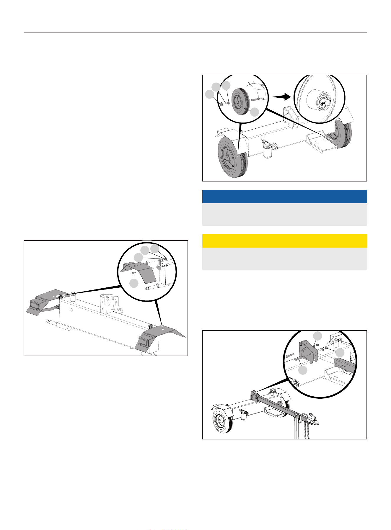
1) install the Fenders
1. Attach the fender to the side of the hydraulic oil tank with an
M10 × 25 bolt (A), Ø10 washer (B), Ø10 lock washer (C) and
M10 nut (D). The safety reflector should be facing the back of
the hydraulic oil tank.
A
B
D
C
2. Repeat with second fender on opposite side
2) install the Wheels
1. Remove the two plastic shipping caps from the wheel hubs.
2. Slide the wheel (A) onto the axle.
3. Be sure the tire valve stem is facing out.
4. Thread the castle nut (B) on the axle and tighten by hand. Use
a wrench to tighten another ¼ turn.
5. Spin the wheel (A) to distribute the bearing grease.
6. Loosen the castle nut (B) and re-tighten by hand.
7. Install the cotter pin (C) through the axle and castle nut.
8. Wheel (A) should spin freely but when grasped on both sides,
should not move from side to side.
9. Install the axle cap (D) using a soft-faced mallet or hammer
and wood block.
10. Repeat for the other wheel.
D
B
C
A
NOTiCE
Keep dirt and debris away from the wheel bearings during
assembly.
CAUTiON
Over-tightening the castle nut will cause the bearings to run
hot and fail prematurely.
3) install the Tow Bar
Attach the tow bar to the bracket on top of the hydraulic oil tank
with two M12 × 80 bolts (A), Ø12 flat washers (B) and M12 lock
nuts (C).
A
B
C
201519 - 37 TON FULL BEAM LOg SPLiTTER
ASSEMBLY
17
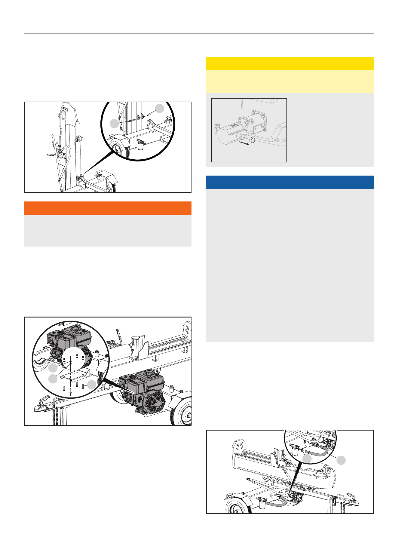
4) install the Beam
1. Stand the beam vertical on the foot plate.
2. Roll the tank into position so the pivot holes of the tank and
beam are aligned.
3. Insert the Pin (A) and secure it with the R-pin (B).
A
B
WARNiNg
The beam is extremely heavy and should always be handled
with 2 or more people. DO NOT try and lift or handle the beam
without assistance.
5) install the Engine
1. Place the engine on the engine mounting platform with the
recoil cover facing outward towards the wheel and align
the 4 holes on the engine base with the holes in the engine
platform.
A
B
C
2. Install a M10 × 45 bolt (A) up through the hole on the engine
platform and through the hole on the engine base.
3. Place a washer (B) on the M10 × 45 bolt (A) and thread a
M10 nylon lock nut (C) onto the bolt and tighten securely.
Tighten to 12 lbf-ft – 15 lbf-ft (16-20 Nm) or fully, then a 1/4
turn further.
4. Repeat steps 2 and 3 for the remaining bolts, washers and
lock nuts.
6) install the Hose and Hydraulic Filter
CAUTiON
Red shipping plugs must be removed from hydraulic pump
prior to installing hoses.
Hydraulic pump may contain
residual oil from
testing procedures
during production.
We recommend using an oil
tray under the pump before
removing the shipping plugs.
NOTiCE
oil inlet (high Pressure) and oil return hoses
Some hoses may be preassembled by the factory, check your
hoses per below instructions to ensure proper assembly.
– These hoses are black and have swivel nuts on both ends.
– The Oil Inlet Hose sends hydraulic oil from the pump to the
control valve/cylinder.
– The Oil Return Hose returns hydraulic oil from the control
valve/cylinder to the tank.
– Hose connections do NOT require thread seal tape. The
O-ring seals against the face of the fittings on the pump
and hose.
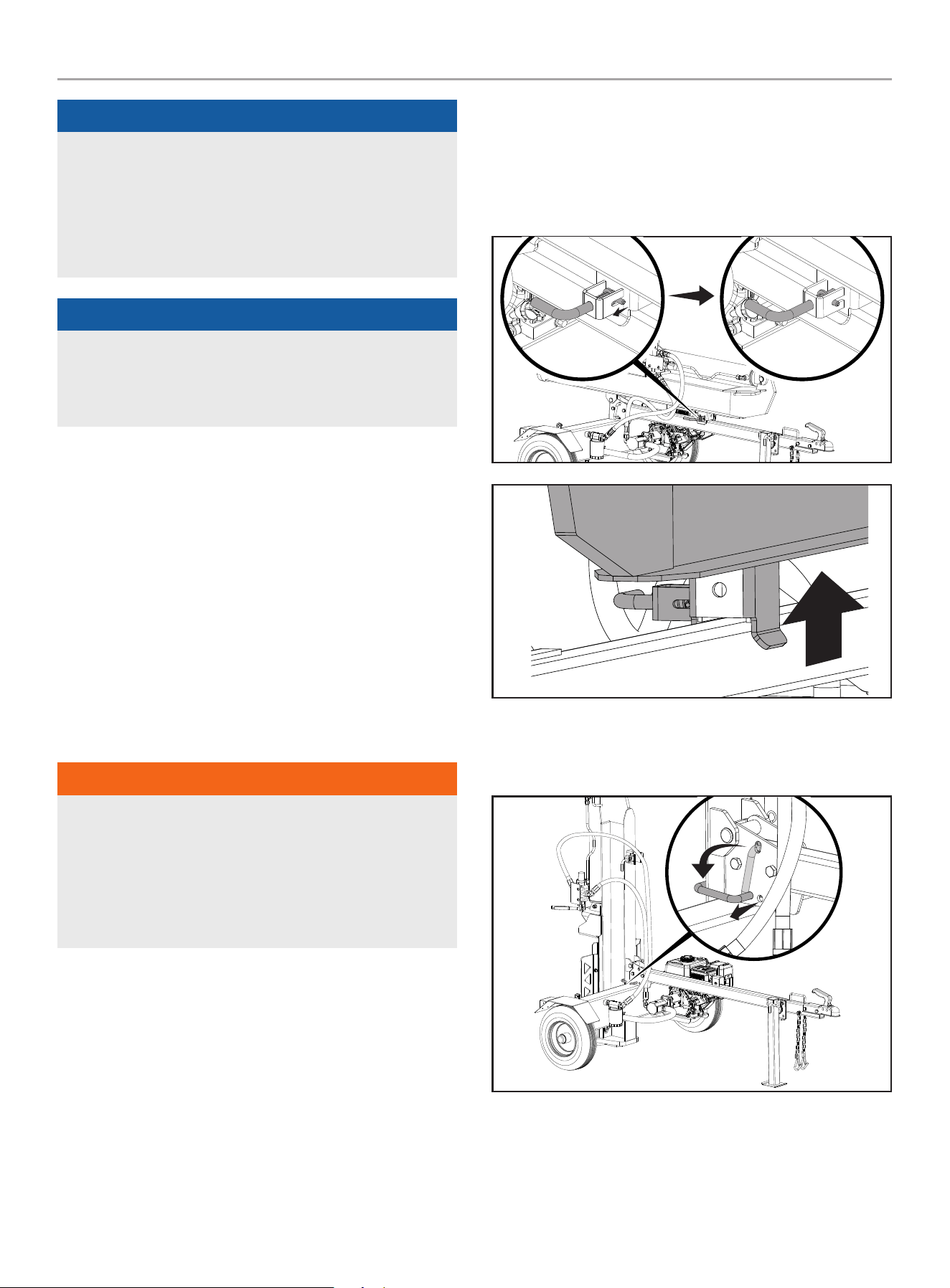
Suction hose
– This is the clear hose that connects the hydraulic tank to
the pump inlet.
– Secure both ends of hose with hose clamps.
Suction hose
1. Using the provided spring loaded hose clamps, connect one
end of the clear oil hose (A) to the hydraulic oil tank (B) and
the other end to the pump inlet on the pump (B). Using a pair
of pliers, squeeze the tabs on the spring loaded hose clamps
together to open them up and slide over the end of the clear
suction hose and mounting fitting and release the pliers to
lock the clamps into place.
A
B
201519 - 37 TON FULL BEAM LOg SPLiTTER
ASSEMBLY
18
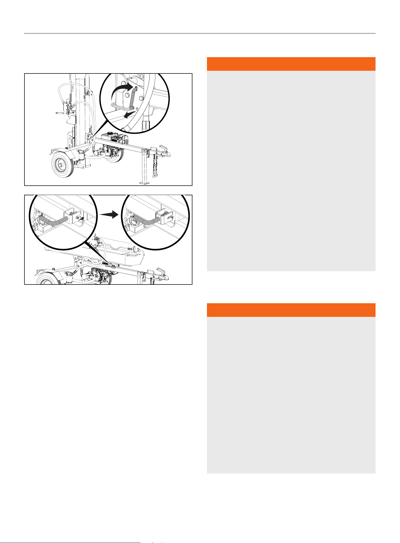
oil inlet (high Pressure) hose
2. Place the provided o-ring into the pump outlet fitting (C) as
shown. Make sure the o-ring is properly seated in the inner
groove of the fitting.
3. Thread the loose end of the high pressure hydraulic hose (D)
onto the pump outlet (C).
4. Securely tighten the hose fitting with a 27mm wrench.
Tighten to 44 lbf-ft - 52 lbf-ft (59.7-70.5 Nm).
D
C
oil return (low Pressure) hose
5. Thread the loose end of the low pressure hydraulic hose
(E) onto the tapered hydraulic fitting on the hydraulic fluid
tank (F). This hose fitting will only fit on this fitting to ensure
correct connection.
6. Securely tighten the fitting with a 27mm wrench. Tighten to
52 lbf-ft - 66 lbf-ft (70.5-89.5 Nm). Make sure the fitting,
when fully tightened is angled upward as shown.
E
F
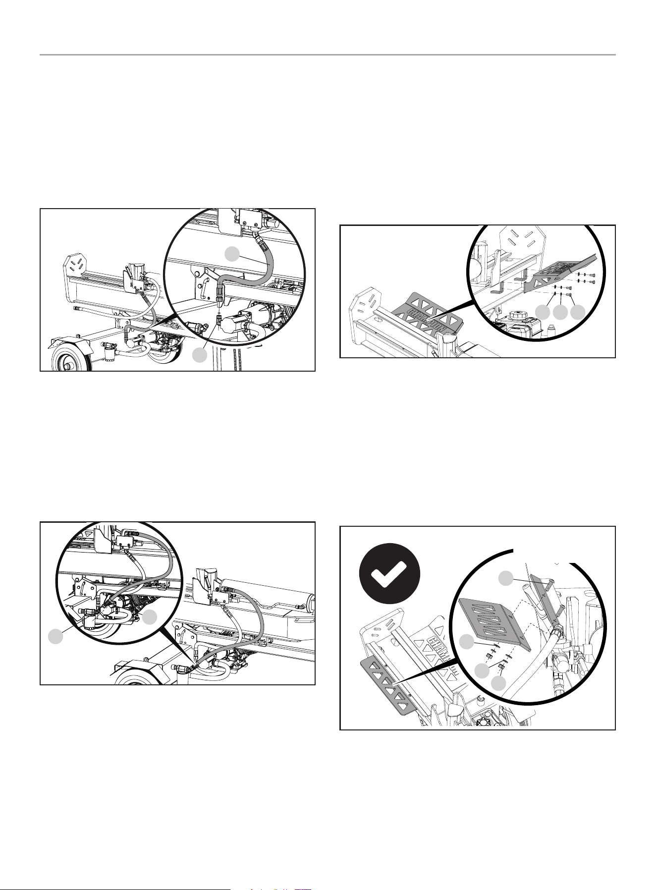
7) install the Log Catchers
large log Catcher (Engine Side)
1. With the log catcher angled upward, align the four holes on
the log catcher with the 4 threaded holes on the log splitter
beam.
2. Place a Ø10 flat washers (A) and Ø10 lock washers (B) onto
the four M10 × 20 bolts (C) and thread them through the
holes on the log catcher and into the holes on the log splitter
beam and tighten securely.
CBA
Small log Catcher (hydraulic hose Side)
3. With the log catcher angled downward and under the lip of
the log splitter beam, align the two holes on the log catcher
with the two holes on the beam lip.
4. Place the two M10 × 30 bolts (D) through the holes on the
beam and through the holes on the log catcher. Place a Ø10
flat washer (E) and a Ø10 lock washer (F) onto the bolt from
the bottom side and thread the M10 nuts (G) onto the bolts
and tighten securely.
CorrECT aSSEmBlY
oriEnTaTion
D
E
F
g

201519 - 37 TON FULL BEAM LOg SPLiTTER
ASSEMBLY
19
inCorrECT aSSEmBlY
oriEnTaTion
D
E
F
g
Add Engine Oil
WARNiNg
DO NOT attempt to crank or start the engine before it has been
properly filled with the recommended type and amount of oil.
Damage to the log splitter as a result of failing to follow these
instructions will void your warranty.
NOTiCE
The recommended oil type is 10W-30 automotive oil.
-20 0 20 40 60
Ambient temperature
Recommended Engine Oil Type
80 100 120
-28.9
°F
°C -17.8 -6.7 4.4 15.6 26.7 37.8 48.9
10W-30
5W-30 Full Synthetic
10W-405W-30
1. Place the log splitter on a flat, level surface.
2. Remove oil fill cap/dipstick to add oil.
3. Using a funnel, add up to 37.2 fl. oz (1100 ml) (include) of oil
and replace oil fill cap/dipstick. DO NOT OVERFILL.
4. Check engine oil level daily and add as needed.
MAX
OIL DIP STICK
NOTiCE
Once oil has been added, a visual check should show oil about
1-2 threads from running out of the fill hole.
If using the dipstick to check oil level, DO NOT screw in the
dipstick while checking.
NOTiCE
Check oil often during the break-in period. Refer to the
Maintenance section for recommended service intervals.
CAUTiON
The engine is equipped with a low oil shut-off and will stop
when the oil level in the crankcase falls below the threshold
level.
NOTiCE
We consider the first 5 hours of run time to be the break-
in period for the engine. During the break in period we
recommend using standard automotive non-synthetic blended
oils. After the break in period synthetic lubricant can be used
but is not required. Avoid bogging or lugging the engine down
and avoid prolonged running at constant RPM. After the 5 hour
break-in period, change the oil.
NOTiCE
Synthetic oil may be used after the 5 hour initial break-
in period. Using synthetic oil does not decrease the
recommended oil change interval. Full synthetic 5W-30 oil will
aid in starting in cold ambient < 41ºF (5ºC)
NOTiCE
Weather will affect engine oil and engine performance. Change
the type of engine oil used based on weather conditions to suit
the engine needs.
201519 - 37 TON FULL BEAM LOg SPLiTTER
ASSEMBLY
20
Add Fuel
DANgER
Gasoline vapors are highly flammable and extremely explosive.
DO NOT light or smoke cigarettes. Fire or explosion can cause
severe burns or death.
Always fill or drain fuel outdoors in a well-ventilated area.
DO NOT pump gasoline directly into the log splitter. Use an
approved container to transfer the fuel to the log splitter.
Never use a gasoline container, gasoline tank, or any other fuel
item that is broken, cut, torn or damaged.
DO NOT overfill the gasoline tank. Always keep fuel away from
sparks, open flames, pilot lights, heat and other sources of
ignition.
Use clean, fresh, regular unleaded gasoline with a minimum
octane rating of 87 and an ethanol content of less than 10% by
volume. ybc
DO NOT mix oil with gasoline.
1. Remove the gasoline cap.
2. Slowly add gasoline to the tank. DO NOT OVERFILL. Gasoline
can expand after filling. A minimum of ¼ in.
(6.4 mm) of space left in the tank is required for gasoline
expansion, although more than ¼ in. (6.4 mm) is
recommended. Gasoline can be forced out of the tank as a
result of expansion if overfilled, and can affect the stable
running condition of the log splitter.
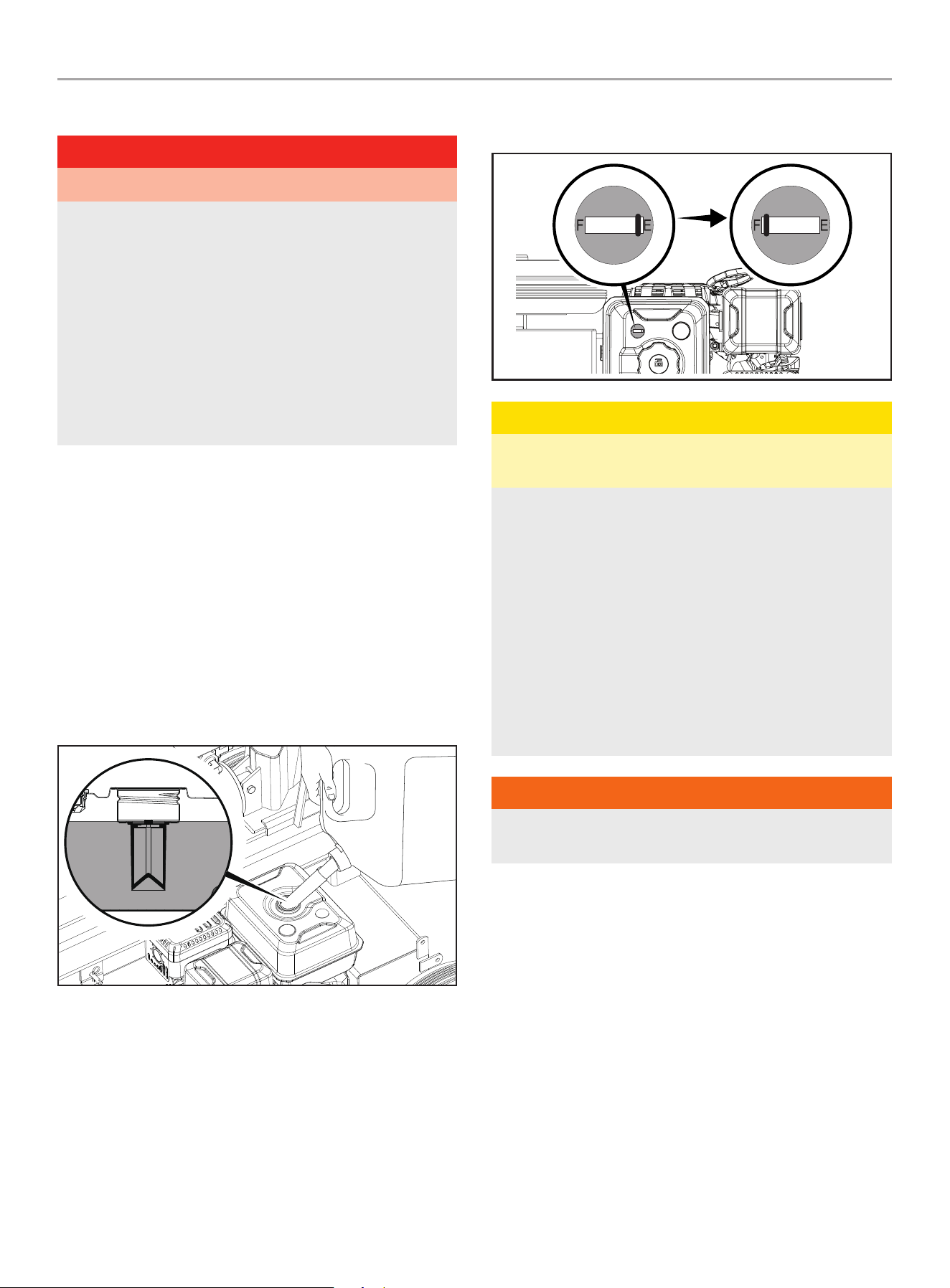
3. The approximate fuel level is shown on the fuel gauge on top
of the fuel tank.
Empty
Full
CAUTiON
Use regular unleaded gasoline with a minimum octane rating
of 87 and an ethanol content of less than 10% by volume.
DO NOT light cigarettes or smoke when filling the tank.
DO NOT mix oil and gasoline.
Fill tank to approximately ¼ in. (6.4 mm) below the top of the
tank to allow for gasoline expansion.
DO NOT pump gasoline directly into the log splitter at the
pump. Use an approved container to transfer the gasoline to
the log splitter.
DO NOT fill tank indoors.
DO NOT fill tank when the engine is running or hot.
DO NOT overfill the tank.
WARNiNg
Pouring gasoline too fast through the fuel screen may result in
blow back of gasoline at the operator while filling.
201519 - 37 TON FULL BEAM LOg SPLiTTER
ASSEMBLY
21
NOTiCE
The engine works well with 10% or less ethanol blended
gasoline. When using ethanol-gasoline blends there are some
issues worth noting:
– Ethanol-gasoline blends can absorb more water than
gasoline alone.
– These ethanol blends can eventually separate, leaving
water or a watery goo in the tank, fuel valve and
carburetor. The compromised gasoline can be drawn into
the carburetor and cause damage to the engine and/or
create potential hazards.
– If a fuel stabilizer is used, confirm that it is formulated to
work with ethanol-gasoline blends.
– Any damages or hazards caused by using ethanol blended
gasoline higher than 10% by volume, improperly stored
gasoline, and/or improperly formulated stabilizers, are not
covered by manufacturer’s warranty.
It is advisable to always shut off the gasoline supply and
run the engine to starvation after each use. See Storage
instructions for extended non-use.
Add Hydraulic Oil
if your log splitter was delivered pre-assembled, follow these
instructions:
1. Position the log splitter on a flat, level surface.
2. Remove the plastic shipping plug from the oil tank on the top
of the tank (A) and discard. Replace with the steel oil plug
(with breather hole) shipped with your log splitter (A).
CAUTiON
Do not run the log splitter with temporary shipping plug.
Pressure will build up inside the tank and potential damage
could occur.
3. After running and cycling the unit several minutes (purging air
from the system), turn off the engine and check the hydraulic
oil level using the oil sight glass. Oil level should visibly fill the
glass sight.
if your log splitter was delivered unassembled, follow these
instructions:
1. Make sure the log splitter is on a flat, level surface.
2. Remove the oil plug from the oil tank (A).
3. Add 5 gal. (18.9 L) of hydraulic oil - see Specification section
for types of acceptable oil.
4. Check the hydraulic oil level using the oil sight glass.
Oil level should visibly fill the sight glass.
A
WARNiNg
DO NOT remove the hydraulic oil fill cap when the engine
is running or hot. Hot oil can escape causing severe burns.
Always allow the log splitter to cool completely before
removing the hydraulic oil cap.
High fluid pressure and temperatures are created in the
hydraulic log splitters. Hydraulic fluid will escape through a
pin-size hole opening and can puncture skin and cause severe
blood poisoning.
Inspect hydraulic system regularly for possible leaks.
Never check for leaks with your hand while the system is
pressurized. Seek medical attention immediately if injured by
escaping fluid.
5. Replace and tighten the oil plug and orient the vent hole away
from the operator zone.
6. Start Engine. (See Starting the Engine section)
7. Extend and retract the wedge to purge air from the hydraulic
system. When the wedge motion is smooth,
the system is properly purged.
8. Check the hydraulic oil tank sight glass. Add approximately 1
gallon (3.8 L) of hydraulic oil to bring the level back up to the
sight glass. Do NOT overfill.
9. Check oil level daily and add as needed.
201519 - 37 TON FULL BEAM LOg SPLiTTER
ASSEMBLY
22
NOTiCE
When the outdoor temperature is below 32˚F (0˚C), Dexron III
transmission fluid can be used. Do not mix hydraulic oil and
transmission fluid. Drain all oil or fluid before adding the other
one.
See Hydraulic Oil System Specifications section for more
details.
NOTiCE
To check oil level, use the oil sight glass on the tank.
The oil sight glass has a marker for the acceptable level of
oil. If oil is below the marker, add oil as needed. DO NOT
OVERFILL.
Before Each Use inspect the Log Splitter
1. Check the hydraulic oil level and visually inspect all hoses,
attachments and cylinder for loose fittings, leaks, cracks,
fraying or other damage.
2. DO NOT operate the log splitter if there is any indication of
damage.
3. Inspect the engine and make sure the oil level is correct
before operating. If the engine is equipped with a spark
arrestor, clean and inspect it regularly (follow spark arrestor
maintenance schedule).
4. The tires need to be fully inflated and in good repair.
Reference the tire sidewall for recommended tire pressure.
WARNiNg
DO NOT over inflate tires. Serious injury can result if tires
explode.
DO NOT tow the log splitter if the tires are worn or will not hold
air.
DO NOT exceed the maximum 45 MPH (72 KM/H) towing
speed.
Changing Beam from Horizontal to Vertical
Orientation
When logs are too heavy to lift, the log splitter beam can be
moved from horizontal to vertical orientation.
To change from horizontal to vertical orientation:
1. Block the wheels to prevent the unit from rolling.
2. Pull the spring loaded pin out on the horizontal beam lock
attached to the tow bar to release the beam. Standing
alongside the hydraulic ram, (opposite side from the engine)
firmly grasp the handle on the beam and lift upward while
pushing the beam back until upright. (Caution, beam is
heavy.)
3. Pull out the spring loaded quick-lock pin and rotate it around
to the 9 o’clock position around the lip on the beam to secure
it in the vertical position.
201519 - 37 TON FULL BEAM LOg SPLiTTER
ASSEMBLY
23
4. To change from vertical to horizontal orientation, reverse the
steps. The beam will automatically lock into the auto-lock on
the tow bar when lowered into position.
Towing Log Splitter Safety
WARNiNg
1. Always check local, state or provincial regulations
regarding towing, licensing and lights before towing your
log splitter. Review towing safety warnings in your towing
vehicle manual.
2. Before towing make sure the log splitter is correctly and
securely attached to the vehicle and the safety chains
attached with enough slack to allow for turning.
3. Before transporting the log splitter, always check that the
fuel valve is OFF and the fuel tank is empty.
4. Support leg must be pinned in the “UP” position for
towing.
5. If using a log splitter cover, ALWAYS remove the cover
before towing the log splitter.
6. Never exceed the max. travel speed of 45 mph (72 km/h).
Towing the log splitter at speeds greater than 45 mph
(72 km/h) could result in serious injury or death. Always
adjust your towing speed according to the terrain and
conditions.
7. Always disconnect the log splitter from the towing vehicle
before operating.
Log Splitter Location
WARNiNg
alWaYS operate the log splitter outdoors.
NEVER place or operate the log splitter near windows, doors,
vents, air intakes or other openings where poisonous engine
exhaust fumes could be drawn into occupied building spaces.
Always maintain a minimum distance of 5 ft. (1.5 m) from dry
combustible vegetation to prevent fires when operating this log
splitter.
Always leave a minimum of 3 ft. (0.9 m) of clearance on all
sides of the log splitter to allow for safe operation, adequate
cooling, maintenance and servicing.
Always place the log splitter on a firm level surface to provide
for good operational footing.
DO NOT work on mud, ice, or in tall grass, brush or snow.
ALWAYS operate log splitter around work zone as shown
below.
201519 - 37 TON FULL BEAM LOg SPLiTTER
OPERATiON
24
horiZonTal oPEraTinG PoSiTion
W
O
R
K
Z
O
N
E
VErTiCal oPEraTinG PoSiTion
W
O
R
K
Z
O
N
E
NOTiCE
For Vertical operation:
– Remove the beam lock-pin from the beam bracket
– Use handle on cylinder to rotate beam to vertical position.
– Insert beam lock-pin in the pivot bracket.
WARNiNg
ALWAYS use the log splitter for its intended use. The log
splitter must always be used to split wood logs, length wise
with the grain.
NEVER modify, change engine settings, operating speeds,
pressure settings or make other changes to the log
splitter. Any modifications could lead to property damage,
cause serious personal injury or death and will void the
manufacturers warranty.
NEVER attach a rope, cable or other device to the control lever
on the log splitter.
ALWAYS operate the log splitter in daylight.
NEVER operate, or let anyone else operate the log splitter
while under the influence of alcohol, drugs, or medication.
NEVER leave the log splitter unattended while the engine is
running.
DO NOT change the splitting position with the engine running.
Contact with a hot muffler can cause serious burns.
ALWAYS make sure the beam is in the locked position.
DO NOT let the beam drop as it could cause serious personal
injury, crush fingers, hands or damage the log splitter.
OPERATiON
DANgER
Always operate log splitter outdoors and far away from
building, windows, doors and intake ventilation covers.
Starting the Engine
1. Make certain the log splitter is on a flat, level surface.
2. Move the fuel valve to the “ON” position.
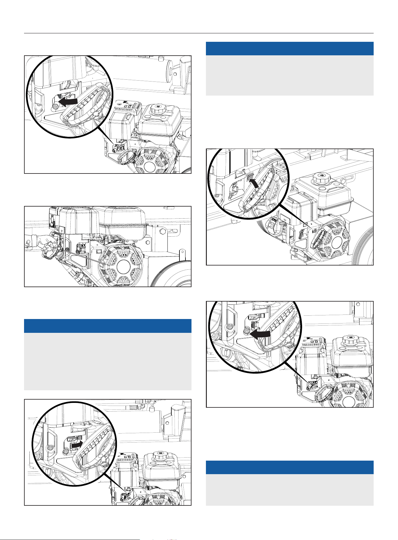
201519 - 37 TON FULL BEAM LOg SPLiTTER
OPERATiON
25
3. Move the choke lever to the “CHOKE” position.
4. Pull the starter cord until resistance is felt and then pull
rapidly.
5. As engine warms up, move the choke lever to the “RUN”
position.
NOTiCE
Keep choke lever in “CHOKE” position for 2 pulls of the recoil
starter. After second pull, move choke lever to the “RUN”
position for up to the next 3 pulls of the recoil starter.
Too much choke leads to spark plug fouling/engine flooding
due to the lack of incoming air. This will cause the engine not
to start.
NOTiCE
If the engine starts but does not run make certain that the log
splitter is on a flat, level surface. The engine is equipped with
a low oil sensor that will prevent the engine from running when
the oil level falls below a critical threshold.
Stopping the Engine
in an emergency, turn the engine switch to the “oFF”
position.
under normal operation:
1. Turn the fuel valve to the “OFF” position.
2. Let the engine run until fuel starvation has stopped the
engine. This usually takes few minutes.
important: Always ensure that the fuel valve is in the “OFF”
position when the engine is not in use.
NOTiCE
If the engine will not be used for a period of two (2) weeks or
longer, please see the Storage section for proper engine and
fuel storage.
201519 - 37 TON FULL BEAM LOg SPLiTTER
OPERATiON
26
Log Splitter Operation
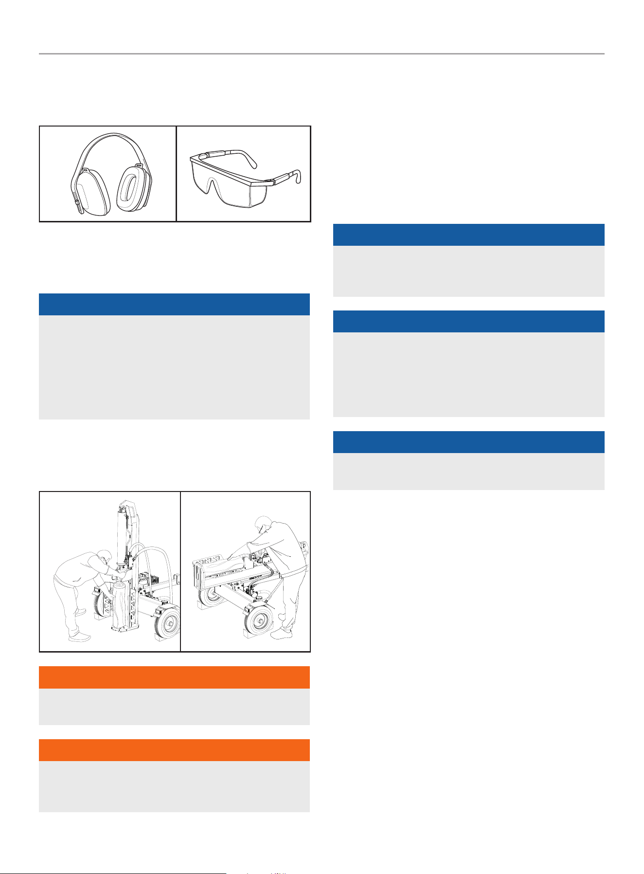
1. ALWAYS wear ear and eye protection, protective clothing and
safety gear.
2. Block tires and ensure support leg is secure to prevent
unintended movement of the log splitter during operation.
3. Set log splitter in either the horizontal or vertical position.
NOTiCE
HORIZONTAL position is used for lighter logs that can easily be
loaded onto the beam.
VERTICAL position is used for light logs as well as heavy logs
that are difficult to load onto the beam.
Back injury can result from lifting logs onto the log splitter if
proper lifting techniques are not used.
4. Load a log onto the beam against the end plate
(MAX LOG LENGTH – 24 in. [61 cm]).
5. To stabilize the log, place your left hand on the side of the log.
Vertical
horizontal
WARNiNg
Never place your hand on the ends of the log, between the log
and end plate or the log and the splitting wedge.
WARNiNg
Only one operator permitted. The adult who loads and
stabilizes the log, must be the person who operates the control
handle.
6. Make sure all limbs are clear of crush zones.
7. Use your right hand to push the control valve handle forward
(towards the end plate) to split the log.
8. Remove left hand from the log once the wedge begins to
contact with the log. Continue holding the control handle in
the forward position until the log splits.
9. Push the auto control valve handle backward to return the
wedge to its original position.
10. Clear the split wood from the work zone.
NOTiCE
It is normal for the hydraulic fluid to appear foamy/frothy
during operation. This can be caused by agitated oil in the tank
collecting air.
NOTiCE
If a log gets stuck, embedded or will not split completely, push
the control handle in the reverse direction and allow the log
splitter to strip the log from the wedge.
ALWAYS keep hands clear of the log and wedge while it is
retracting.
NOTiCE
The cylinder stroke is designed so the wedge stops
approximately 1.5 in. (3.8 cm) from the end plate.
Operation at High Altitude
The density of air at high altitude is lower than at sea level. Engine
power is reduced as the air mass and air-fuel ratio decrease.
Engine power and log splitter output will be reduced approximately
3½% for every 1000 ft. of elevation above sea level. This is a
natural trend and cannot be changed by adjusting the engine. At
high altitudes increased exhaust emissions can also result due to
the increased enrichment of the air fuel ratio. Other high altitude
issues can include hard starting, increased fuel consumption and
spark plug fouling.
To alleviate high altitude issues other than the natural power
loss, CPE can provide a high altitude carburetor main jet. The
alternative main jet and installation instructions can be obtained
by contacting our Technical Support Team. Installation instructions
are also available in the Technical Bulletin area of the CPE website.
The part number and recommended minimum altitude for the
application of the high altitude carburetor main jet is listed in the
table below.
201519 - 37 TON FULL BEAM LOg SPLiTTER
MAiNTENANCE
27
In order to select the correct high altitude main jet it is necessary
to identify the carburetor model. For this purpose, a code is
stamped on the side of the carburetor. Select the correct high
altitude jet part number corresponding to the carburetor code
found on your particular carburetor.
Carb. Code high alt. Jet Part number min. altitude
16100-
000047
16161-000039
3000-6000 ft.
(914.4-1828.8 m)
16161-000038
6000-8000 ft.
(1828.8-2438.4 m)
WARNiNg
Operation using the alternative main jet at elevations lower
than the recommended minimum altitude can damage the
engine. For operation at lower elevations, the originally
supplied standard main jet must be used. Operating the
engine with the wrong engine configuration at a given altitude
may increase its emissions and decrease fuel efficiency and
performance.
MAiNTENANCE
Make certain that the log splitter is kept clean and stored properly.
Always operate the unit on a flat, level surface in a clean, dry
operating environment. DO NOT expose the unit to extreme
conditions, excessive dust, dirt, moisture or corrosive vapors.
Inspect all air vents and cooling slots to ensure that they are clean
and unobstructed.
Clean spark arrester every 100 hours.
Check and tighten all bolts and nuts before operating the log
splitter.
WARNiNg
Never operate a damaged or defective log splitter.
WARNiNg
Improper maintenance will void your warranty.
NOTiCE
For Emission control devices and systems, read and
understand your responsibilities for service as stated in the
Emission Control Warranty Statement of this manual.
The owner/operator is responsible for all periodic maintenance.
Complete all scheduled maintenance in a timely manner.
Correct any issue before operating the log splitter.
For service or parts assistance, contact our
Technical Support Team at 1-877-338-0999.
Cleaning the Log splitter
CAUTiON
DO NOT spray engine with water.
Water can contaminate the fuel system and can enter the
engine through the cooling slots and damage the engine.
Clear the debris from the beam, wedge and endplate.
Use a damp cloth to clean exterior surfaces of the engine and log
splitter.
Use a soft bristle brush to remove excess dirt and oil.
Use an air compressor (25 PSI) to clear dirt and small debris.
Wipe all metal parts with an oily rag to help prevent rust and
corrosion.
Changing the Engine Oil
Change oil when the engine is warm. Refer to the oil specification
to select the proper grade for your operating environment.
1. Remove the oil drain plug with a 12 mm socket
(not included) and extension.
DRAIN BOLT
2. Allow the oil to drain completely into an appropriate container.
3. Replace the oil drain plug.
4. Remove the oil fill cap/dipstick to add oil.
5. Add oil according to Add Engine Oil in Assembly section.
DO NOT OVERFILL. Oil not included for routine maintenance.
6. Dispose of used oil at an approved waste management
facility.
NOTiCE
Once oil has been added, a visual check should show oil
about 1-2 threads from running out of the fill hole. If using the
dipstick to check oil level, DO NOT screw in the dipstick while
checking.
201519 - 37 TON FULL BEAM LOg SPLiTTER
MAiNTENANCE
28
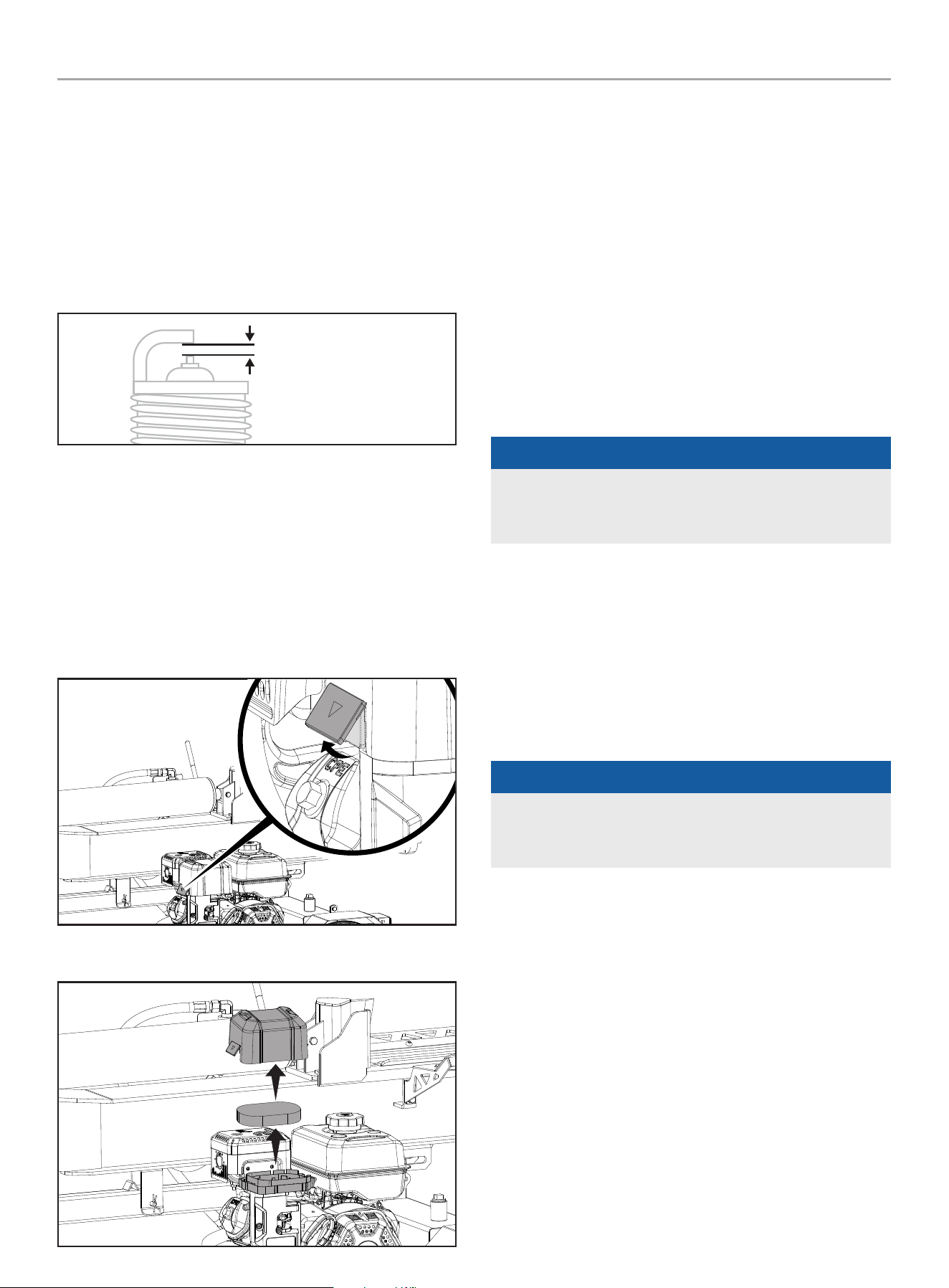
Cleaning and Adjusting the Spark Plug(s)
1. Remove the spark plug cable from the spark plug.
2. Use a spark plug socket tool (not included), or a
13/16 in. (21 mm) socket (not included) to remove the plug.
3. Inspect the electrode on the plug. It must be clean and not
worn to produce the spark required for ignition.
4. Make certain the spark plug gap is
0.028-0.031 in. (0.7-0.8 mm).
SPARK PLUG GAP
5. Refer to the spark plug types in Specifications when replacing
the plug.
6. Firmly re-install the plug.
7. Attach the spark plug cable to the spark plug.
Cleaning the Air Filter
1. Using your finger, pry the outer tab up slightly and lift the air
filter cover above the tab lock position.
2. Remove both air filter cover and air filter element.
3. Wash in liquid detergent and water. Squeeze thoroughly dry in
a clean cloth.
4. Saturate in clean engine oil.
5. Squeeze in a clean, absorbent cloth to remove all excess oil.
6. Place the filter in the assembly.
7. Reattach the air filter cover. Attach the side closest to the
gas tank then pivot down to close. Make sure air filter cover
snaps in place.
Changing the Hydraulic Oil
Always shut off the engine, disconnect the spark plug.
Change the hydraulic oil filter after the first 50 hours of use, then
every 100 hours or seasonally.
NOTiCE
When log splitters are not used for extended periods of time
and they are exposed to changing temperature conditions,
moisture through condensation can build up inside the tank.
1. Begin with the cylinder retracted and the engine fuel valve in
the “OFF” position.
2. Release any stored pressure by moving the valve lever
forward and backward several times.
3. Place a container under the hydraulic tank. Make sure
it is large enough to hold the contents of the tank.
See model specification section of this manual for hydraulic
oil capacities.
NOTiCE
The drain plug is sealed with Teflon
®
tape. Add 2-3 wraps of
new Teflon
®
tape as needed when replacing the drain plug to
prevent oil leak.
4. To drain the oil,
– Place an oil drain container under the drain plug. Unscrew
(counter-clockwise) and remove the tank drain plug on
the bottom of the hydraulic tank. Allow oil to completely
drain from the tank into the container. Re-apply Teflon
®
sealing tape to the drain plug threads, then reinsert and
turn (clockwise) in the tank drain plug. Tighten, but do not
over tighten.
– Place an oil drain container under the external oil filter.
Unscrew (counter-clockwise) and remove the external
hydraulic oil filter and drain any oil in the filter into the
container. A strap or oil filter wrench may be needed.
201519 - 37 TON FULL BEAM LOg SPLiTTER
MAiNTENANCE
29
NOTiCE
Oil will drain from the filter and filter housing.
– Locate an approved replacement filter.
– Lubricate the gasket of the new filter with a thin film
of clean oil.
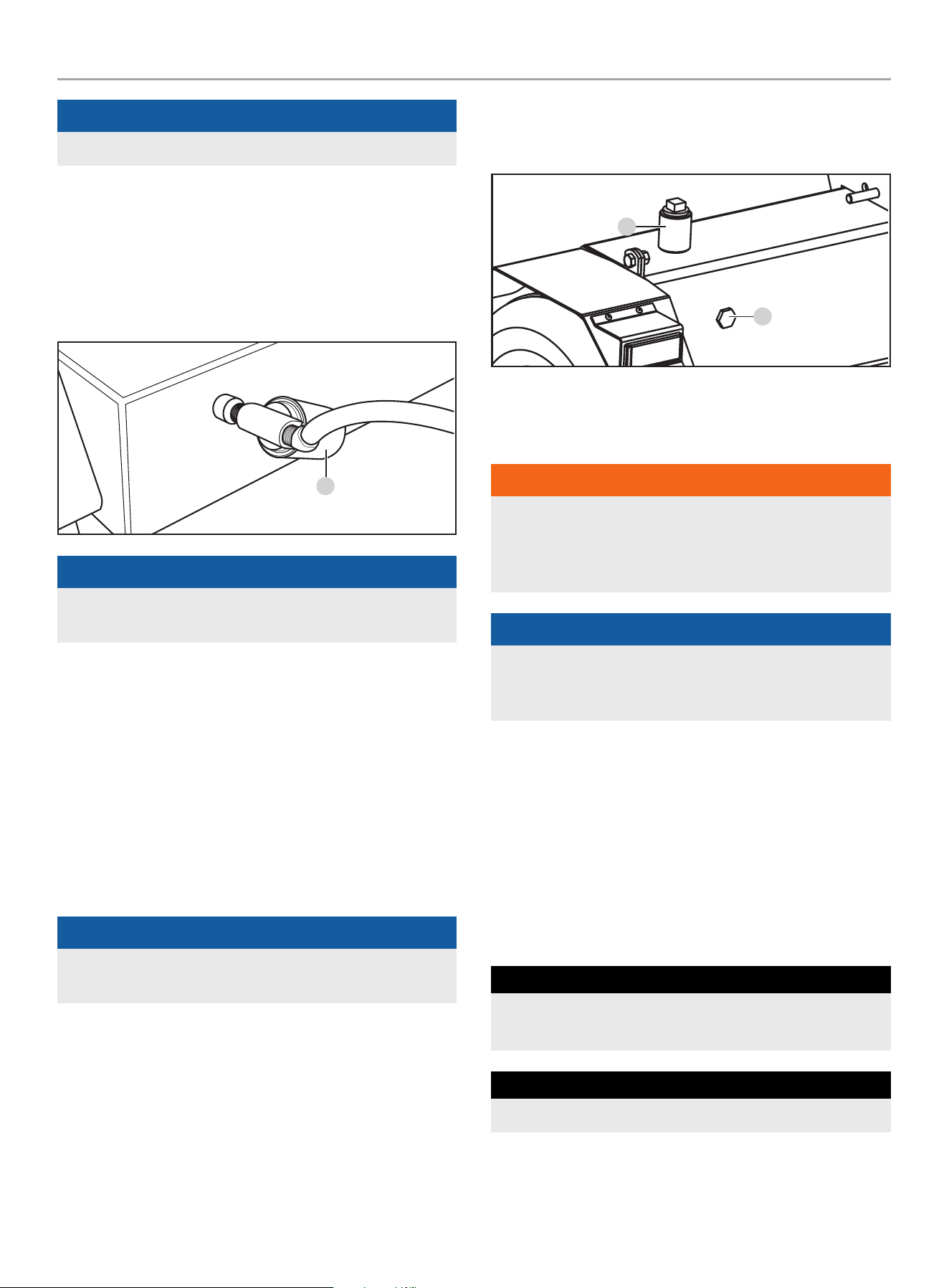
– Install a new hydraulic oil filter (A). Screw the new
filter on clockwise. Tighten 3/4 - 1 turn after the
gasket makes contact.
A
NOTiCE
Install a new hydraulic oil filter each time the hydraulic oil is
changed (if your log splitter includes this feature).
– Place an oil drain container under the large clear hose
that runs from the tank to the pump.
– Loosen the hose clamp attached to the fitting on the
tank.
– Disconnect hose from fitting and drain oil into the
container.
– Using a large wrench, unscrew the fitting from the
tank to expose the internal tank filter.
– Check for any debris on the screen. Using a clean
towel or air gun, carefully remove any debris.
NOTiCE
Be careful when handling the screen as it can be easily
damaged.
– Apply new Teflon
®
sealing tape to threads, reinsert
into tank and tighten. Be careful to tighten, but do
not over tighten.
5. Unscrew and remove the tank fill plug on top of the tank (B).
Using a funnel, add approximately 5 gal. (18.9 L) of hydraulic
oil to the tank. Wipe up any spilled oil.
6. Turn the fuel valve to the “ON” position, and start
the engine. Purge the air from the system by extending and
retracting the wedge several times until the motion is smooth.
7. Check the hydraulic oil level using the sight glass.
Add 1 gal (3.8 L) of hydraulic oil, so the oil level is visible in
the sight glass (C).
B
C
8. Dispose of used oil at approved recycling locations in
accordance with Federal, State, Local or Provincial
regulations.
WARNiNg
Always shut off the engine, disconnect the spark plug, and
relieve system pressure before cleaning, adjusting, or repairing
the log splitter. Relieve system pressure by moving split control
lever back and forth several times
NOTiCE
Refer to Specifications for a list of compatible replacement
filters or call Champion Power Equipment at
1-877-338-0999 to order a replacement OEM filter.
Maintenance Schedule
Follow the service intervals indicated in the following maintenance
schedule.
Service your log splitter more frequently when operating in
adverse conditions.
Contact our Technical Support Team at 1-877-338-0999 to locate
the nearest CPE certified service dealer for your log splitter or
engine maintenance needs.
EVErY 8 hourS or DailY
Check engine and hydraulic oil levels
Clean around air intake and muffler
FirST 5 hourS
Change oil

201519 - 37 TON FULL BEAM LOg SPLiTTER
STORAgE
30
EVErY 50 hourS or EVErY SEaSon
Clean air filter
Change oil if operating under heavy load or in hot
environments
EVErY 100 hourS or EVErY SEaSon
Change oil
Clean/adjust spark plug
Check/adjust valve clearance*
Clean spark arrestor
Clean fuel tank and filter*
Change hydraulic oil
Change hydraulic oil filter
EVErY 250 hourS
Clean combustion chamber*
EVErY YEar
Inspect wheel bearings and repack bearing grease as
needed.
EVErY 3 YEarS
Replace fuel line*
* To be performed by knowledgeable, experienced owners or CPE certified service
centers.
STORAgE
Refer to the Maintenance section for proper cleaning instructions.
Log Splitter Storage
1. The log splitter needs to be cool for at least 5 minutes before
storing.
2. Clean the log splitter before storage according to the
Maintenance section.
3. Retract the wedge to protect the rod from corrosion.
4. Wipe the beam and wedge with an oily rag to prevent rust
and corrosion.
Engine Stored for Less than 30 Days
1. Allow the engine to cool completely before storage.
2. Clean engine according to the Maintenance section.
3. To extend the fuel storage life add a properly formulated fuel
stabilizer to the tank.
4. Ensure the fuel valve is in the “OFF” position.
Engines Stored for Over 30 Days
1. Add a properly formulated fuel stabilizer to the tank.
2. Run the engine for a few minutes so the treated fuel cycles
through the fuel system and carburetor.
3. Turn the fuel valve to the “OFF” position.
4. Let the engine run until fuel starvation has stopped the
engine. This usually takes a few minutes.
5. The engine needs to cool completely before cleaning and
storage.
6. Clean the engine according to the Maintenance section.
7. Change the oil.
8. Remove the spark plug and pour about 14.8 mL (
1
⁄2 ounce) of
oil into the cylinder. Using the Recoil, crank the engine slowly
to distribute the oil and lubricate the cylinder.
9. Reattach the spark plug.
WARNiNg
Never store the log splitter indoors next to appliances where
there is a source of heat or open flame, spark or pilot light
because they can ignite gasoline vapors.
DO NOT store a log splitter near fertilizer or any corrosive
material. Even with an empty gas tank, gasoline vapors could
ignite.

201519 - 37 TON FULL BEAM LOg SPLiTTER
SPECiFiCATiONS
31
SPECiFiCATiONS
Log Splitter Specifications
Ram Force ................................................... 37 Ton
Cycle Time .............................................. 16 seconds
Hydraulic Tank Capacity ............................. 5 gal (18.9 L)
Max Log Length ......................................24 in. (61 cm)
Max Log Weight .....................................100 lb. (45 kg)
Coupler Ball Size ..................................... 2 in. (5.1 cm)
Tire Size ........................................... 16 in. (40.6 cm)
Max towing speed ..............................45 MPH (72 KM/H)
Cylinder size ................... 5 in. × 23 in. (12.7 cm × 58.4 cm)
Cylinder rod size ................................... 1.8 in. (4.5 cm)
Gear Pump .................................................. 2-stage
Max pressure .............................................. 3600 psi
Max flow capacity ............................. 17 GPM (64.4 LPM)
Control Valve ..................................Detent (auto-return)
Net Weight ....................................... 560.1 lb. (254 kg)
Length ..........................................86.3 in. (219.2 cm)
Width ........................................... 51.3 in. (130.2 cm)
Height ........................................... 41.7 in. (105.8 cm)
Engine Specifications
Model ........................................................ R338P
Displacement ................................................ 338 cc
Type ................................................... 4-Stroke OHV
Start Type ...................................................Manual
Oil Specifications
DO NOT OVERFILL.
Type ................................................ See chart below
Capacity .......................................37.2 fl. oz (1100 ml)
-20 0 20 40 60
Ambient temperature
Recommended Engine Oil Type
80 100 120
-28.9
°F
°C -17.8 -6.7 4.4 15.6 26.7 37.8 48.9
10W-30
5W-30 Full Synthetic
10W-405W-30
NOTiCE
Temperature will affect engine oil and engine performance.
Change the type of engine oil used based on temperature
shown in the “Recommended Engine Oil Type” table.
Hydraulic Oil System
Capacity ............................................. 6 gal. (22.7 L)
For year round use in warmer climates (always aBoVE
32˚F/ 0˚C):
– ISO 32/SAE10W
– Universal Hydraulic Oil
For year round use in colder climates (BEloW 32˚F/ 0˚C):
– Automatic Transmission Fluid
replacement filters:
– Fram PH9342
– K&N HP-2008
– Wix 51361
Fuel Specifications
Use regular unleaded gasoline with a minimum octane rating of 87
and an ethanol content of less than 10% by volume. DO NOT USE
E15 or E85. DO NOT OVERFILL.
Gasoline Capacity ................................. 1.45 gal. (5.5 L)
Spark Plug Specifications
OEM Type .................................................... F6RTC
Replacement Type ..................... NGK BPR6ES or equivalent
Gap ................................. 0.028-0.031 in. (0.7-0.8 mm)
Valve Specifications
Intake Clearance ................ 0.002-0.0039 in. (0.05-0.1 mm)
Exhaust Clearance .............. 0.002-0.0039 in. (0.05-0.1 mm)
NOTiCE
A technical bulletin regarding valve adjustment procedures is
available at www.championpowerequipment.com.
important Message About Temperature
Your product is designed and rated for continuous operation at
ambient temperatures up to 104°F (40°C). When your product
is needed it may be operated at temperatures ranging from 5°F
(-15°C) to 122°F (50°C) for short periods of time. If exposed to
temperatures outside this range during storage, it should be
brought back within this range before operation. In any event, the
product must always be operated outdoors, in a well-ventilated
area and away from doors, windows and vents.
NOTiCE
When temperature is below 32ºF (0ºC) use Automatic
Transmission Fluid (Dexron-III or similar).

201519 - 37 TON FULL BEAM LOg SPLiTTER
TROUBLESHOOTiNg
32
TROUBLESHOOTiNg
Problem Cause Solution
Engine will not start.
No fuel. Add fuel.
Faulty spark plug. Replace spark plug.
Unit loaded during start up. Remove load from unit.
Engine will not start;
Engine starts but runs roughly.
Low oil level.
Fill crankcase to the proper level.
Place log splitter on a flat, level surface.
Choke in the wrong position. Adjust choke.
Spark plug wire loose. Attach wire to spark plug.
Engine shuts down during operation.
Out of fuel. Fill fuel tank.
Low oil level.
Fill crankcase to the proper level. Place log
splitter on a flat, level surface.
Engine cannot supply enough power or
overheating.
Insufficient ventilation.
Check for air restriction. Move to a well
ventilated area.
Wedge movement is slow or erratic.
Air in the hydraulic oil system.
Purge air by extending and retracting the wedge
several times until motion is smooth.
Debris lodged in beam guides. Clear debris from beam.
Low hydraulic oil. Check oil level and add as needed.
Oil leak from cylinder.
Faulty cylinder rod seal. Contact Customer Service.
Scored or bent cylinder rod. Contact Customer Service.
Loose hydraulic fitting. Tighten hydraulic fitting.
Faulty combination washer seal on
cylinder hydraulic fitting.
Contact Customer Service.
Wedge will not extend or retract.
Faulty control valve. Contact Customer Service.
Faulty hydraulic pump. Contact Customer Service.
Low hydraulic oil. Check oil level and add as needed.
Excessive bouncing while towing. Under-inflated tires.
Inflate tires to proper pressure. Refer to tire
sidewall.
For further technical support:
Technical Support Team
Toll Free 1-877-338-0999
support@championpowerequipment.com

WARRANTY*
CHAMPION POWER EQUIPMENT
2 YEAR LIMITED WARRANTY
Warranty Qualifications
To register your product for warranty and FREE lifetime call center
technical support please visit:
https://www.championpowerequipment.com/register
To complete registration you will need to include a copy of the
purchase receipt as proof of original purchase. Proof of purchase
is required for warranty service. Please register within ten (10)
days from date of purchase.
Repair/Replacement Warranty
CPE warrants to the original purchaser that the mechanical and
electrical components will be free of defects in material and
workmanship for a period of two years (parts and labor) from
the original date of purchase and 180 days (parts and labor) for
commercial and industrial use. Transportation charges on product
submitted for repair or replacement under this warranty are the
sole responsibility of the purchaser. This warranty only applies to
the original purchaser and is not transferable.
Do Not Return The Unit To The Place Of
Purchase
Contact CPE’s Technical Service and CPE will troubleshoot any
issue via phone or e-mail. If the problem is not corrected by
this method, CPE will, at its option, authorize evaluation, repair
or replacement of the defective part or component at a CPE
Service Center. CPE will provide you with a case number for
warranty service. Please keep it for future reference. Repairs or
replacements without prior authorization, or at an unauthorized
repair facility, will not be covered by this warranty.
Warranty Exclusions
This warranty does not cover the following repairs and equipment:
Normal Wear
Products with mechanical and electrical components need
periodic parts and service to perform well. This warranty does not
cover repair when normal use has exhausted the life of a part or
the equipment.
Installation, Use and Maintenance
This warranty will not apply to parts and/or labor if the product is
deemed to have been misused, neglected, involved in an accident,
abused, loaded beyond the product’s limits, modified, installed
improperly or connected incorrectly to any electrical component.
Normal maintenance is not covered by this warranty and is not
required to be performed at a facility or by a person authorized by
CPE.
Other Exclusions
This warranty excludes:
– Cosmetic defects such as paint, decals, etc.
– Wear items such as filter elements, o-rings, etc.
– Accessory parts such as hoses, storage covers, etc.
– Failures due to acts of God and other force majeure events
beyond the manufacturer’s control.
– Problems caused by parts that are not original Champion
Power Equipment parts.
Limits of Implied Warranty and
Consequential Damage
Champion Power Equipment disclaims any obligation to cover
any loss of time, use of this product, freight, or any incidental
or consequential claim by anyone from using this product.
THIS WARRANTY AND THE ATTACHED U.S. EPA and/or CARB
EMISSION CONTROL SYSTEM WARRANTIES (WHEN APPLICABLE)
ARE IN LIEU OF ALL OTHER WARRANTIES, EXPRESS OR IMPLIED,
INCLUDING WARRANTIES OF MERCHANTABILITY OR FITNESS
FOR A PARTICULAR PURPOSE.
This warranty gives you certain legal rights which may change
from state to state or province to province. Your state or province
may also have other rights you may be entitled to that are not
listed within this warranty.
Contact Information
Address
Champion Power Equipment, Inc.
6370 S Pioneer Way, Unit 101
Las Vegas, NV 89113 USA
www.championpowerequipment.com
Customer Service
Toll Free: 1-877-338-0999
info@championpowerequipment.com
Fax no.: 1-562-236-9429
Technical Service
Toll Free: 1-877-338-0999
tech@championpowerequipment.com
EMERGENCY 24 HOUR SUPPORT: 1-562-204-1188
*Except as otherwise stipulated in any of the following enclosed Emission Control System Warranties (when applicable) for the Emission Control System: U.S. Environment Protection Agency
(EPA) and/or California Air Resources Board (CARB).

CHAMPION POWER EQUIPMENT, INC. (CPE)
AND THE UNITED STATES ENVIRONMENTAL PROTECTION AGENCY (U.S. EPA)
EMISSION CONTROL SYSTEM WARRANTY
Your Champion Power Equipment (CPE) engine complies with U.S. EPA emissions regulations.
YOUR WARRANTY RIGHTS AND OBLIGATIONS:
The US EPA and CPE are pleased to explain the Federal Emission Control Systems Warranty on your 2024 small off-road engine (SORE)
and engine powered equipment. New engines and equipment must be designed, built and equipped, at the time of sale, to meet U.S.
EPA regulations for small off-road engines (SORE). CPE warrants the emission control system on your small off-road engine (SORE)
and equipment for the period of time listed below, provided there has been no abuse, neglect, unapproved modification, or improper
maintenance of your equipment.
Your emission control system may include parts such as the carburetor, fuel-injection system, the ignition system, catalytic converter and
fuel lines. Also included may be hoses, belts, connectors and other emission related assemblies. Where a warrantable condition exits, CPE
will repair your small off-road engine (SORE) at no cost to you including diagnosis, parts and labor.
MANUFACTURER’S EMISSION CONTROL SYSTEM WARRANTY COVERAGE:
This emission control system is warranted for two years, subject to provisions set forth below. If, during the warranty period, an emission
related part on your engine is defective in materials or workmanship, the part will be repaired or replaced by CPE.
OWNER WARRANTY RESPONSIBILITIES:
As the small off-road engine (SORE) owner, you are responsible for the performance of the required maintenance listed in your Owner’s
Manual. CPE recommends that you retain all your receipts covering maintenance on your small off-road engine, but CPE cannot deny
warranty solely for the lack of receipts or for your failure to ensure the performance of all scheduled maintenance.
As the small off-road engine (SORE) owner, you should however be aware that CPE may deny you warranty coverage if your small, off-road
engine (SORE) or a part has failed due to abuse, neglect, improper maintenance or unapproved modifications.
You are responsible for presenting your small off-road engine (SORE) to an Authorized CPE service outlet or alternate service outlet as
described in (3)(f.) below, CPE dealer or CPE, Las Vegas, NV. as soon as a problem exists. The warranty repairs should be completed in a
reasonable amount of time, not to exceed 30 days.
If you have any questions regarding your warranty rights and responsibilities, you should contact:
Champion Power Equipment, Inc.
Customer Service
6370 S Pioneer Way, Unit 101
Las Vegas, NV 89113
1-877-338-0999
tech@championpowerequipment.com

EMISSION CONTROL SYSTEM WARRANTY
The following are specific provisions relative to your Emission Control System (ECS) Warranty Coverage.
1. APPLICABILITY: This warranty shall apply to 1997 and later model year small off-road engines (SORE). The ECS Warranty Period shall
begin on the date the new engine or equipment is delivered to its original, end-use purchaser, and shall continue for 24 consecutive
months thereafter.
2. GENERAL EMISSIONS WARRANTY COVERAGE
CPE warrants to the original, end-use purchaser of the new engine or equipment and to each subsequent purchaser that each of its
small off-road engines (SORE) is:
2a. Designed, built and equipped so as to conform to U.S. EPA emissions standards for spark-ignited engines at or below 19 kilowatts.
2b. Free from defects in materials and workmanship that cause the failure of a warranted part to be identical in all material respects
to the part as described in the engine manufacturer’s application for certification for a period of two years.
3. THE WARRANTY ON EMISSION-RELATED PARTS WILL BE INTERPRETED AS FOLLOWS:
3a. Any warranted part that is not scheduled for replacement as required maintenance in the Owners Manual shall be warranted for
the ECS Warranty Period. If any such part fails during the ECS Warranty Period, it shall be repaired or replaced by CPE according
to Subsection “d” below. Any such part repaired or replaced under the ECS Warranty shall be warranted for any remainder of the
ECS Warranty Period.
3b. Any warranted, emissions-related part which is scheduled only for regular inspection as specified in the Owners Manual shall be
warranted for the ECS Warranty Period. A statement in such written instructions to the effect of “repair or replace as necessary”,
shall not reduce the ECS Warranty Period. Any such part repaired or replaced under the ECS Warranty shall be warranted for the
remainder of the ECS Warranty Period.
3c. Any warranted, emissions-related part which is scheduled for replacement as required maintenance in the Owner’s Manual shall
be warranted for the period of time prior to the first scheduled replacement point for that part. If the part fails prior to the first
scheduled replacement, the part shall be repaired or replaced by CPE according to Subsection “d” below. Any such emissions-
related part repaired or replaced under the ECS Warranty, shall be warranted for the remainder of the ECS Warranty Period prior to
the first scheduled replacement point for such emissions-related part.
3d. Repair or replacement of any warranted, emissions-related part under this ECS Warranty shall be performed at no charge to the
owner at a CPE Authorized Service Outlet.
3e. The owner shall not be charged for diagnostic labor which leads to the determination that a part covered by the ECS Warranty is in
fact defective, provided that such diagnostic work is performed at a CPE Authorized Service Outlet.
3f. CPE shall pay for covered emissions warranty repairs at non-authorized service outlets under the following circumstances:
i. The service is required in a population center with a population over 100,000 according to U.S. Census 2000 without a CPE
Authorized Service Outlet AND
ii. The service is required more than 100 miles from a CPE Authorized Service Outlet. The 100 mile limitation does not apply in the
following states: Alaska, Arizona, Colorado, Hawaii, Idaho, Montana, Nebraska, Nevada, New Mexico, Oregon, Texas, Utah and
Wyoming.
3g. CPE shall be liable for damages to other original engine components or approved modifications proximately caused by a failure
under warranty of an emission-related part covered by the ECS Warranty.
3h. Throughout the ECS Warranty Period, CPE shall maintain a supply of warranted emission-related parts sufficient to meet the
expected demand for such emission-related parts.
3i. Any CPE Authorized and approved emission-related replacement part may be used in the performance of any ECS Warranty
maintenance or repair and will be provided without charge to the owner. Such use shall not reduce CPE’s warranty obligation.
3j. Unapproved add-on or modified parts may not be used to modify or repair a CPE engine. Such use voids this ECS Warranty and
shall be sufficient grounds for disallowing an ECS Warranty claim. CPE shall not be liable hereunder for failures of any warranted
parts of a CPE engine caused by the use of such an unapproved add-on or modified part.

EMISSION-RELATED PARTS INCLUDE THE FOLLOWING: (using those portions of the list
applicable to the engine)
Systems covered by this
warranty
Parts Description
Fuel Metering System Fuel regulator, Carburetor and internal parts
Air Induction System Air cleaner, Intake manifold
Ignition System Spark plug and parts, Magneto ignition system
Exhaust System Exhaust manifold, catalytic converter
Miscellaneous Parts Tubing, Fittings, Seals, Gaskets, and Clamps associated with these listed systems.
Evaporative Emissions Fuel Tank, Fuel Cap, Fuel Lines (for liquid fuel and fuel vapors), Fuel Line Fittings, Clamps, Pressure
Relief Valves, Control Valves, Control Solenoids, Electronic Controls, Vacuum Control Diaphragms,
Control Cables, Control Linkages, Purge Valves, Gaskets, Liquid/Vapor Separator, Carbon Canister,
Canister Mounting Brackets, Carburetor Purge Port Connector
TO OBTAIN WARRANTY SERVICE:
You must take your CPE engine or the product on which it is installed, along with your warranty registration card or other proof of original
purchase date, at your expense, to any Champion Power Equipment dealer who is authorized by Champion Power Equipment, Inc. to
sell and service that CPE product during his normal business hours. Alternate service locations defined in Section (3)(f.) above must be
approved by CPE prior to service. Claims for repair or adjustment found to be caused solely by defects in material or workmanship will not
be denied because the engine was not properly maintained and used.
If you have any questions regarding your warranty rights and responsibilities, or to obtain warranty service, please write or call
Customer Service at Champion Power Equipment, Inc.
Champion Power Equipment, Inc.
6370 S Pioneer Way, Unit 101
Las Vegas, NV 89113
1-877-338-0999
Attn.: Customer Service
tech@championpowerequipment.com

MANUAL DEL OPERADOR
MODELO #201519
PARTIDOR DE TRONCOS DE 37
TONELADAS CON VIGA COMPLETA
Champion Power Equipment, Inc.
o visite championpowerequipment.com
LEA Y GUARDE ESTE MANUAL. Este manual contiene precauciones de seguridad importantes que deben ser leídos y entendidos antes de operar el producto. El
fallar en hacerlo puede resultar en lesiones graves. Este manual debe permanecer con el producto.
Las especificaciones, descripciones e ilustraciones en este manual son tan precisos tal como se conocía en el tiempo de la publicación, pero son sujetos a cambios
sin previo aviso.
5296-M-OP REV 20240906
ES
ACTIVE SU GARANTÍA
registrando su producto:
championpowere quipment.com

201519 - PARTIDOR DE TRONCOS DE 37 TONELADAS CON VIGA COMPLETA
TAbLE Of CONTENTS
2
TAbLE Of CONTENTS
Introducción ................................................. 3
Definiciones de Seguridad
............................ 3
Instrucciones de Seguridad Importantes
..... 4
Seguridad de Combustible ........................................ 6
Instrucciones de Entrenamiento .................................. 7
Preparación ........................................................ 8
Operación .......................................................... 8
Mantenimiento .................................................... 9
Etiquetas de Seguridad y de la Placa de Datos ................. 10
Símbolos de Operación .......................................... 13
Símbolos de la Etiqueta de Inicio Rápido ........................ 13
Controles y Características .........................14
Partidor de Troncos .............................................. 14
Motor ............................................................. 15
Partes Incluidas .................................................. 16
Montaje ........................................................17
Abra la Caja de Transporte ...................................... 17
1) Instale los Guardabarros ...................................... 17
2) Instale las Llantas ............................................. 17
3) Instale la Barra de Remolque ................................. 17
4) Instale la Viga ................................................. 18
5) Instale el Motor ................................................ 18
6) Instale la Manguera y el Filtro Hidráulico..................... 18
7) Instale los Receptores de Troncos ............................ 19
Agregue Aceite del Motor ........................................ 20
Agregue Combustible ............................................21
Agregue Aceite Hidráulico ....................................... 22
Inspeccione el Partidor de Troncos Antes de Cada Uso ........23
Cambiando la Viga de Orientación Horizontal a Vertical ........23
Remolque Seguro del Partidor de Troncos ...................... 24
Ubicación del Partidor de Troncos ............................... 24
Operación ................................................... 25
Encendido del Motor .............................................25
Parada del Motor ................................................. 26
Operación del Partidor de Troncos .............................. 27
Operación a Gran Altura .........................................28
Mantenimiento ............................................ 28
Limpiando el Partidor de Troncos ...............................29
Cambiando el Aceite del Motor ..................................29
Limpiando y Ajustando las Bujías ...............................29
Limpiando el Filtro de Aire ....................................... 29
Cambiando el Aceite Hidráulico .................................30
Programa de Mantenimiento .................................... 31
Almacenamiento ..........................................32
Almacenamiento del Partidor de Troncos ....................... 32
El Motor Almacenado por Menos de 30 Días ................... 32
El Motor Almacenado Durante más de 30 Días ................. 32
Especificaciones ......................................... 33
Especificaciones del Partidor de Troncos .......................33
Especificaciones del Motor ......................................33
Especificaciones del Aceite ...................................... 33
Sistema de Aceite Hidráulico ....................................33
Especificaciones de Combustible ................................ 33
Especificaciones de la Bujía .....................................33
Especificaciones de la Válvula ................................... 33
Un Aviso Importante Sobre Temperatura ........................34
Solución de Problemas ............................... 35
PARA EL DESGLOSE DE PARTES
Buscar por número de modelo en
championpowerequipment.com

201519 - PARTIDOR DE TRONCOS DE 37 TONELADAS CON VIGA COMPLETA
INTRODUCCIóN
3
INTRODUCCIóN
Felicitaciones por la compra de un producto de Champion
Power Equipment (CPE). CPE diseña, desarrolla y apoya todos
nuestros productos con las especificaciones y normas estrictas.
Con conocimiento adecuado del producto, uso seguro y un
mantenimiento regular, este producto debe llevar años de servicio.
Se ha hecho todo lo posible por garantizar la exactitud e integridad
de la información en este manual en el tiempo de su publicación,
y nos reservamos el derecho de cambiar, alterar y/o mejorar el
producto y este documento en cualquier momento sin previo aviso.
Así como en CPE valoramos altamente cómo nuestros productos
son diseñados, fabricados, operados y mantenidos, y también
altamente valoramos su seguridad y la seguridad de los demás,
nos gustaría que tomará el tiempo para leer este manual y otros
materiales del producto a fondo y ser plenamente conscientes y
conocedores del montaje, operación, peligros y mantenimiento
del producto antes de su uso. Familiarícese totalmente a sí
mismo, y asegúrese de que otros que planean operar el producto
se familiaricen sobre el funcionamiento del producto, con los
procedimientos de seguridad y funcionamiento correcto antes de
cada uso.
Por favor siempre use el sentido común y siempre esté atento a la
precaución cuando utilice el producto para asegurar que no ocurra
un accidente, daños materiales o lesiones. Queremos que siga
utilizando y que esté satisfecho con su producto CPE en los años
venideros.
Cuando contacte a CPE sobre partes y/o servicio, necesitará
proveer los números completos de modelo y serie de su producto.
Escriba la información que se encuentra en la etiqueta de
información de su producto a la tabla en la parte
de abajo.
Equipo dE Apoyo Técnico dE cpE
1-877-338-0999
nÚMERo dE ModELo
201519
nÚMERo dE SERiE
FEcHA dE coMpRA
LuGAR dE coMpRA
DEfINICIONES DE SEGURIDAD
El propósito de los símbolos de seguridad es para atraer su
atención a los peligros posibles. Los símbolos, y sus explicaciones,
merecen su comprensión y atención cuidadosa. Las advertencias
de seguridad no por si mismos eliminan cualquier peligro. Las
instrucciones o advertencias que dan no son sustitutos para
medidas apropiadas de prevención de accidentes.
PELIGRO
PELIGRO indica una situación peligrosa que, de no evitarse,
resultará en la muerte o lesión grave.
ADVERTENCIA
ADVERTENCIA indica una situación peligrosa que, de no
evitarse, puede resultar en la muerte o lesión grave.
PRECAUCIóN
PRECAUCIÓN indica una situación peligrosa que, de no
evitarse, puede resultar en lesiones moderadas o mínimas.
AVISO
AVISO indica información considerada importante, pero no
relacionada a un peligro (ej. mensajes relacionados a daños de
propiedad).

201519 - PARTIDOR DE TRONCOS DE 37 TONELADAS CON VIGA COMPLETA
INSTRUCCIONES DE SEGURIDAD IMPORTANTES
4
INSTRUCCIONES DE SEGURIDAD
IMPORTANTES
ADVERTENCIA
Cáncer y Daño Reproductivo – www.P65Warnings.ca.gov
PELIGRO
El motor contiene monóxido de carbono, un gas venenoso
incoloro e inodoro. El respirar monóxido de carbono causará
nausea, mareo, desmayos o la muerte. Si usted se siente
mareado o débil, salga al aire fresco de inmediato.
opere el partidor de troncos SoLo a la intemperie en un
área bien ventilada.
NO opere el partidor de troncos dentro de ningún inmueble,
incluyendo garajes, sótanos, espacios de arrastre, cobertizos,
o armario.
NO permita que las emanaciones del escape ingresen a una
zona con poco espacio por las ventanas, puertas, orificios de
ventilación u otras aberturas.
PELIGRO
El uso de un motor en interiores puEdE MATARLo En
MinuToS. El escape del motor contiene monóxido de carbono.
Éste es un veneno que no se puede ver ni oler.
nuncA lo use dentro del hogar ni el garaje, incLuSo Si las
puertas y ventanas están abiertas.
Úselo SiEMpRE a la inTEMpERiE lejos de ventanas, puertas,
y orificios de ventilación.
ADVERTENCIA
Aunque el partidor de troncos contiene un supresor de
chispas, mantenga una distancia mínima de 5 ft. (1.5 m) de
vegetación seca para evitar incendios.
ADVERTENCIA
Las chispas pueden causar incendio o descargas eléctricas.
Al dar servicio al partidor de troncos:
Desconecte el cable de la bujía y colóquelo donde no haga
contacto con la misma bujía.
NO revise si hay chispa con la bujía retirada.
Use probadores de chispas aprobados solamente.
ADVERTENCIA
Los motores en marcha producen calor. El tocarlos puede
causar quemaduras graves. El material combustible puede
incendiarse al hacer contacto.
NO toque superficies calientes.
Evite el contacto con gases de escape calientes.
Deje que el equipo se enfríe antes de tocarlo.
Mantenga al menos 3 ft. (91.4 cm) de espacio libre en todos
los lados para garantizar un enfriamiento adecuado.
ADVERTENCIA
Peligro de aplastamiento.
La cuña puede penetrar la piel y romper los huesos. Mantenga
todas las extremidades lejos de la cuña y la placa extrema.
ADVERTENCIA
Peligro de proyectiles.
Durante la operación del partidor de troncos, pueden salir
expulsados trozos del tronco. Siempre use gafas de seguridad
aprobadas por ANSI al operar la unidad. Esté atento.
ADVERTENCIA
Mantenga la zona de trabajo del operador libre de residuos
mientras trabaja para garantizar una base segura.
PELIGRO
Peligro de inyección cutánea.
El aceite hidráulico que escapa bajo alta presión puede
penetrar en la piel y causar lesiones corporales graves. En
el caso de que el aceite hidráulico pueda penetrar en la piel
y evitar infecciones graves como gangrena, busque atención
médica adecuada inmediatamente.

201519 - PARTIDOR DE TRONCOS DE 37 TONELADAS CON VIGA COMPLETA
INSTRUCCIONES DE SEGURIDAD IMPORTANTES
5
ADVERTENCIA
Asegúrese siempre de que todas las conexiones de aceite
hidráulico estén firmemente aseguradas y de que las
mangueras hidráulicas estén en buen estado, sin cortes,
desgarros o daños antes de aplicar presión al sistema.
ADVERTENCIA
Mantenga siempre las manos y las partes del cuerpo alejadas
de las boquillas o orificios que puedan expulsar el aceite
hidráulico a alta presión en caso de fuga de aceite.
NUNCA use sus propias manos para buscar fugas. Las fugas
pueden detectarse usando cartón, papel o madera de desecho
sobre el área sospechosa.
ADVERTENCIA
Peligro de remolque.
Siempre consulte con su municipio local, estado o provincia
regulaciones con respecto a remolque, luces y licencias antes
de remolcar su partidor de troncos en las carreteras públicas.
ANTES de remolcar, revise todas las advertencias de
seguridad del manual del vehículo de remolque. Conduzca de
forma segura. Tenga en cuenta la longitud añadida del partidor
de troncos.
NUNCA monte ni transporte carga en el partidor de troncos.
NO exceda la velocidad máxima de remolque de 45 MPH
(72 KM/h).
ADVERTENCIA
Antes de retirar el pasador instalado en la pata de soporte
delantero, asegúrese de que el enganche esté instalado en el
vehículo. Liberar el pasador antes hará que la pata de soporte
se deslice hacia arriba y posiblemente cause lesiones.
ADVERTENCIA
La retracción rápida del cable del arrancador tirará la mano y
el brazo hacia el motor más rápido de lo que usted se imagina.
Podrían producirse huesos rotos, fracturas, moretones o
esguinces.
El inicio involuntario puede provocar enredos, amputación
traumática o laceración.
Al arrancar el motor, jale lentamente el cable del arrancador
hasta sentir resistencia, luego jálelo rápidamente para evitar
contragolpes.
PRECAUCIóN
Partes del sistema hidráulico (cilindro, bomba, válvulas y
mangueras) podrían estar extremamente caliente durante
operación.
ADVERTENCIA
El trato o uso indebidos del partidor puede dañarlo, reducir su
vida útil y anular la garantía.
SIEMPRE use el partidor en las tareas para las cuales está
diseñada.
SIEMPRE opérelo en superficies niveladas.
NO exponga el motor a condiciones de humedad, polvo o
suciedad excesivos.
NO permita que ningún material bloquee las ranuras de
ventilación.
no use el motor si:
– El equipo emite chispas, humo o llamas.
– El equipo vibra excesivamente

201519 - PARTIDOR DE TRONCOS DE 37 TONELADAS CON VIGA COMPLETA
INSTRUCCIONES DE SEGURIDAD IMPORTANTES
6
Seguridad de Combustible
PELIGRO
GASoLinA y VApoRES dE GASoLinA Son ALTAMEnTE
inFLAMABLES y EXpLoSiVoS.
El fuego o una explosión pueden causar quemaduras severas e
inclusivo la muerte.
La gasolina y los vapores de gasolina:
– Vapores de gasolina son altamente inflamables y explosivos.
– Vapores de gasolina pueden causar un incendio o una
explosión si se encienden.
– Gasolina es un combustible líquido y los resultantes vapores
de gasolina pueden encenderse y causar un fuego o explosión.
– La gasolina es un irritante de la piel y necesita ser limpiada de
inmediato si se derrama sobre la piel o la ropa.
– La gasolina tiene un olor particular, esto le ayudará a detectar
posibles fugas de forma rápida.
– En cualquier fuego de gas de petróleo, las llamas no se deben
extinguir al menos que al hacerlo la válvula de suministro de
combustible esté APAGADA. Esto es porque si un incendio se
ha extinguido y un suministro de combustible no se desactiva,
entonces un riesgo de explosión puede ser creado.
– Los vapores de gasolina se expanden o se contraen con
temperaturas ambientales. Nunca llene el tanque de gasolina
pasando el indicador FULL (lleno) en el filtro de combustible,
ya que los vapores de la gasolina necesitan espacio para
expandir si las temperaturas suben.
ADVERTENCIA
Al agregar o sacar combustible:
No encienda ni fume cigarrillos.
Siempre detenga el motor y deje enfriar durante un mínimo de
dos minutos antes de repostar.
Siempre afloje la tapa de gasolina lentamente para liberar
la presión de vapor y evitar que el combustible se escape
alrededor de la tapa de gasolina.
Siempre reemplace y apriete la tapa de gasolina de forma
segura después de repostar.
Nunca retire la tapa de gasolina ni agregue gasolina mientras
el motor está funcionando o cuando el motor está caliente.
Siempre llene o drene la gasolina a la intemperie solamente y
en una zona bien ventilada.
No bombee gasolina directamente al partidor de troncos en la
estación de servicio.
Siempre guarde la gasolina en un recipiente que cumpla con la
EPA/CARB o para transferir la gasolina al partidor de troncos.
No rebose el tanque de gasolina.
Siempre mantenga la gasolina lejos de chispas, llamas
expuestas, luces piloto, calor y otras fuentes de encendido.
ADVERTENCIA
Al arrancar el partidor de troncos:
No intente arrancar un partidor de troncos dañado.
Siempre verifique de que la tapa de la gasolina, el filtro de
aire, la bujía, las líneas de combustible y el sistema de escape
estén correctamente instalados.
Siempre permita que el combustible derramado se evapore
totalmente antes de arrancar el motor.
Cerciórese de que el partidor de troncos descanse nivelado en
el suelo.
ADVERTENCIA
Al operar el partidor de troncos:
No mueva ni incline el partidor de troncos durante la
operación.
ADVERTENCIA
Al transportar o dar servicio al partidor de troncos:
Siempre verifique de que la válvula de combustible esté en la
posición APAGADO y el tanque de gasolina esté vacío.
Desconecte el cable de la bujía.

201519 - PARTIDOR DE TRONCOS DE 37 TONELADAS CON VIGA COMPLETA
INSTRUCCIONES DE SEGURIDAD IMPORTANTES
7
ADVERTENCIA
Al almacenar el partidor de troncos:
Guárdelo lejos de chispas, llamas expuestas, luces piloto, calor
y otras fuentes de encendido.
No almacene el partidor de troncos o gasolina cerca hornos,
calentadores de agua, o cualquier otro aparato que produzca
calor o tenga encendidos automáticos.
PELIGRO
Nunca coloque un recipiente de gasolina, tanque de gasolina,
cilindro de GLP o cualquier material combustible en el camino
de la transmisión del escape durante la operación del motor.
ADVERTENCIA
Nunca use un recipiente de gasolina, tanque de gasolina,
o cualquier otro elemento de combustible que está quebrado,
cortado, roto o dañado.
Instrucciones de Entrenamiento
PRECAUCIóN
1. Lea completamente el manual del operador antes de usar
este partidor de troncos.
2. No permita que nadie use el partidor de troncos si no ha
leído el manual del operador ni ha sido entrenado en su
uso seguro.
3. Nunca deje que niños ni adultos no entrenados operen
esta máquina.
4. Accidentes se producen cuando más de una (1) persona
opera el partidor de troncos. Si un asistente ayuda
cargando los troncos en el partidor, nunca accione los
controles sino hasta que la persona se haya alejado del
área.
5. Nunca transporte carga en el partidor de troncos o monte
en la máquina.
6. En los partidores de troncos hidráulicos se acumulan altas
presiones de líquido. El líquido hidráulico presurizado que
escapa a través de la abertura de un orificio del pasador
puede perforar la piel y causar infecciones graves o
intoxicación sanguínea. Por lo tanto, las instrucciones
siguientes deben acatarse en todo momento.
– No opere la unidad con mangueras, uniones ni tubos
raídos, torcidos, rotos ni dañados.
– Detenga el motor y libere la presión del sistema
hidráulico antes de cambiar o ajustar uniones,
mangueras, tubos u otros componentes del sistema.
– No modifique los ajustes de presión de la bomba ni de
la válvula.
– No revise si hay fugas con la mano. Las fugas se
pueden detectar pasando cartón o madera sobre el
área sospechosa. Vea si hay decoloración. Si resulta
lesionado debido al escape de líquido, consulte
a un médico inmediatamente. Si no recibe de
inmediato tratamiento médico apropiado puede sufrir
infecciones o reacciones graves.
7. Mantenga la zona del operador y el área adyacente
despejada para tener un equilibrio seguro.
8. Su partidor de troncos está equipado con un motor de
combustión interna y no está diseñado para su uso cerca
de ningún bosque, maleza o tierra cubierta de hierba
no aprobada. Siempre consulte con su municipio local,
regulaciones estatales y federales antes de su uso.
9. Los partidores de troncos deben usarse solamente para
partir madera.

201519 - PARTIDOR DE TRONCOS DE 37 TONELADAS CON VIGA COMPLETA
INSTRUCCIONES DE SEGURIDAD IMPORTANTES
8
Preparación
PRECAUCIóN
1. Familiarícese completamente con los controles y el uso
correcto del equipo.
2. Equipo de seguridad :
– Siempre use calzado de seguridad y botas para
trabajo pesado.
– Siempre use antiparras o gafas de seguridad al operar
la máquina.
– No use joyas ni ropa suelta que pudiera enredarse en
las partes móviles o giratorias de la máquina.
3. Cerciórese de que el partidor de troncos esté en una
superficie nivelada. Bloquee las llantas y coloque ambas
patas de apoyo en la posición de ABAJO para impedir
movimientos accidentales del partidor durante la
operación.
– Siempre opere el partidor de troncos desde la zona
del operador indicada por el fabricante.
4. Los troncos que se van a partir en unidades tipo ariete
deben ser lo más cuadrados posibles.
Operación
PRECAUCIóN
1. Repase todas las reglas de seguridad antes de poner
en marcha este partidor de troncos. El no acatar estas
reglas puede causar lesiones graves al operador o a los
espectadores.
2. Asegúrese de revisar antes de cada uso que todas las
conexiones y las abrazaderas de las mangueras estén
bien ajustadas. Con el tiempo, existe la posibilidad de que
las conexiones se aflojen con la vibración
3. Nunca deje sola la máquina con el motor encendido.
4. Nunca opere la máquina cuando esté bajo la influencia del
alcohol, drogas o medicamentos.
5. El propietario de la máquina debe instruir a todos los
operadores sobre el uso seguro del partidor de troncos.
6. Siempre opere el partidor de troncos con el equipo de
seguridad en su lugar y todos los controles correctamente
ajustados para una operación segura.
7. Siempre opere el partidor de troncos a la velocidad
recomendada por el fabricante.
8. Siempre mantenga las manos y pies lejos de las partes
móviles.
9. Cuando cargue un partidor de troncos tipo ariete, coloque
las manos en los lados del tronco, no en los extremos.
Nunca coloque las manos ni ninguna parte del cuerpo
entre un tronco y alguna parte del partidor.
10. En los partidores de troncos tipo ariete, nunca intente
partir más de un (1) tronco a la vez si el ariete no se ha
extendido plenamente y no se requiere un segundo tronco
para completar la separación del primero.
11. En los partidores de troncos tipo ariete en los cuales
los troncos no se cortan cuadrados, la parte más larga
del tronco debe girarse hacia abajo y el extremo más
cuadrado del mismo debe colocarse contra el ariete.
12. Sólo parta troncos con el grano de la leña.
13. Nunca parta perpendicular al grano de la leña.
14. Use solamente las manos para operar los controles del
partidor.
15. No recargue combustible a un motor en marcha o
caliente.
16. Siempre apague el motor y espere un mínimo de 2
minutos para enfriar el motor antes de remover la tapa del
tanque de gasolina previo a recargar combustible.

201519 - PARTIDOR DE TRONCOS DE 37 TONELADAS CON VIGA COMPLETA
INSTRUCCIONES DE SEGURIDAD IMPORTANTES
9
Mantenimiento
PRECAUCIóN
1. Siempre apague el motor mientras repara o ajusta
el partidor de troncos, salvo según lo recomiende el
fabricante.
2. Limpie los desechos y la paja del cilindro del motor,
las aletas de la culata del cilindro, la tapa del arrancador
retráctil y las áreas del silenciador. El motor viene con
un silenciador parachispas, límpielo e inspecciónelo
regularmente (siga las instrucciones de servicio del
fabricante). Reemplácelo si está dañado.
3. Verifique que todas las tuercas y tornillos estén apretados
para garantizar el buen estado del equipo.
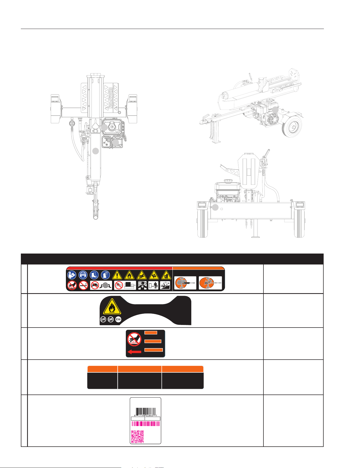
201519 - PARTIDOR DE TRONCOS DE 37 TONELADAS CON VIGA COMPLETA
INSTRUCCIONES DE SEGURIDAD IMPORTANTES
10
Vista superior
Vista trasera
Etiquetas de Seguridad y de la Placa de Datos
Estas etiquetas le advierten acerca de peligros potenciales que pueden causar lesiones graves. Lea atentamente las etiquetas.
Si una etiqueta se desprende o es ilegible, comuníquese con Equipo de Apoyo Técnico para un posible reemplazo.
ETiquETA dEScRipciÓn
A
1117-L-SF-B
DANGER PELIGRO WARNING ADVERTENCIA AVERTISSEMENT DANGER
HORIZONTAL WORK ZONE
AREA DE TRABAJO HORIZONTAL
ZONE DE TRAVAIL HORIZONTALE
K 485 2945 109 30%K
ColorsLPN 1117-L- SF
Rev A
Size 19 0 x 44 mm
Artwork Notes
3mm corner radius; 2mm safe margin
Revision Changes
-Added s afe work zone
This art work belongs to Champ ion Power Equipment. T he contents are con fidential and privil eged and shall not be discl osed to or used by or for
outside pa rties without t he explicit consen t of Champion Power Eq uipment.
VERTICAL WORK ZONE
AREA DE TRABAJO VERTICAL
ZONE DE TR AVAIL VERTICALE
Símbolos deseguridad
B
2018-L-OP-B
ESSENCE SANS PLOM SEULEMENT.
Indice d’octane minimal de
87. Maximum 10 % d'éthanol.
La clasificación mínimo de 87
octano. Máximo de etanol de 10%.
GASOLINA SIN PLOMO SOLAMENTE.UNLEADED FUEL ONLY.
Minimum octane rating of 87.
Maximum 10% ethanol.
K 109 --- --- ---
ColorsLPN 2 018-L-OP
Rev B
Size Special
Artwork Notes
3mm corner radius; 2mm safe margin;
to be printed
on
WHITE
substrate.
Revision Changes
B -Cha nge octan e rating 8 5 to octane r ating 87
(20200409)
This artwork belongs to Champion Power Equipment. The contents are confidential and privileged and shall not be disclosed to or used by or for
outside p arties withou t the explicit conse nt of Champion Power E quipment.
Combustible
c
1966-L-SF-B
DO NOT TOUCH!
Hot surface.
WARNING
¡NO TOCAR!
Superficie caliente.
ADVERTENCIA
AVERTISSEMENT
NE TOUCHEZ PAS!
Surface chaude.
K 485 152 --- ---
ColorsLPN 1966-L-SF
Rev B
Size 59 x 42 mm
Artwork Notes
3mm corner radius; 2mm safe margin;
white t o be
prin ted shown in 5 0% process m agenta
Revision Changes
B: Upd ate size to ma tch Rota 301cc - - 202309 15
This artwork belongs to C hampion Power Equipment. The contents are confiden tial and privileged and shall not be disclosed to or used by or for
outside p arties withou t the explicit conse nt of Champion Power E quipment.
Superficie caliente
d
4572-L-SF-B
WARNING ADVERTENCIA AVERTISSEMENT
Before transporting,
ALWAYS check that
the fuel valve is OFF
and fuel tank is empty.
Antes del transporte, compruebe
SIEMPRE que la válvula de
combustible está CERRADA y que el
tanque de combustible está vacío.
Avant le transport, vérifiez
TOUJOURS que le robinet de
carburant est FERMÉ et que le
réservoir de carburant est vide.
152 K --- --- ---
ColorsAPN 4572-L-SF
Rev B
Size 112 x 23 mm
Artwork Notes
2mm corner radius; 2mm safe margin;
to be printed
on
WHITE
substrate.
Revision Changes
B: optimize size (20240424)
This artwork belongs to Champion Power Equipment. The contents are confidential and privileged and shall not be disclosed to or used by or for
outside parties without the explicit consent of Champion Power Equipment.
Válvula de combustible y
tanque de gasolina
E
CHAMPION POWER EQUIPMENT, INC.
6370 S PIONEER WAY, UNIT 101
LAS VEGAS, NV 89113
USA / É.-U. • 1-877-338-0999
WWW.CHAMPIONPOWEREQUIPMENT.COM
MADE IN CHINA / FABRIQUÉ EN CHINE
5361-L-PR-A
SERIAL NO.
N° DE SÉRIE
MODEL
MODÈLE
201519
REGISTER TO
ACTIVATE YOUR
WARRANTY
ENREGISTREZ-VOUS POUR
ACTIVEZ VOTRE
GARANTIE
XXXXXXXXXXXX
K --- --- --- ---
ColorsAPN 5361-L-PR
Rev A
Size 51 x 76 mm
Artwork Notes
3mm cor ner radius ; 2mm safe mar gin; to be prin ted
on secu rity subst rate; magen ta text to be fill ed in
durin g time of prod uction
Revision Changes
--
This art work belongs to Cham pion Power Equipment. T he contents are con fidential and privi leged and shall not be disc losed to or used by or for
outside p arties withou t the explicit consen t of Champion Power E quipment.
Placa de datos
A
b
C
D
Vista lateral
E

201519 - PARTIDOR DE TRONCOS DE 37 TONELADAS CON VIGA COMPLETA
INSTRUCCIONES DE SEGURIDAD IMPORTANTES
11
Símbolos de Seguridad
Algunos de los siguientes símbolos pueden ser utilizados en este producto. Por favor estúdielos y aprenda sus significados.
La interpretación apropiada de estos símbolos le permitirán que opere su producto de forma más segura.
SÍMBoLo SiGniFicAdo
Lea el manual del operador. Para reducir el riesgo de lesiones, el usuario debe leer y
comprender el manual del operador antes de usar este producto.
protección Auditiva y ocular. Siempre use gafas de seguridad o lentes de seguridad con
escudos laterales, y como sea necesario una máscara protectora al igual que protección auditiva
completa cuando opere este producto.
calzado. Siempre use zapatos de seguridad o botas pesadas cuando opere la máquina.
Guantes. Siempre use guantes protectores antideslizantes de trabajo pesado cuando opere este
producto.
Alerta de Seguridad. Precauciones que involucran su seguridad.
Riesgo de incendio. El combustible y sus vapores son extremadamente inflamables y explosivos.
El fuego puede producir quemaduras severas o la muerte. No agregue combustible mientras el
motor esté en marcha o caliente.
peligro de inyección cutánea. El aceite hidráulico a alta presión puede inyectarse bajo la piel.
Cerciórese de que todas las conexiones estén firmemente apretadas antes de aplicar presión.
Libere la presión del sistema antes de efectuar reparaciones.
Siempre mantenga la manos alejadas de la cuña y el ariete. Partes móviles pueden aplastar o
cortar.
Siempre mantenga los pies alejados de la cuña y el ariete. Partes móviles pueden aplastar o
cortar.

201519 - PARTIDOR DE TRONCOS DE 37 TONELADAS CON VIGA COMPLETA
INSTRUCCIONES DE SEGURIDAD IMPORTANTES
12
SÍMBoLo SiGniFicAdo
Superficie caliente. Para reducir el riesgo de lesión o daños, evite el contacto con cualquier
superficie caliente.
Alerta de llama expuesta. El combustible y sus vapores son extremadamente inflamables y
explosivas. Mantenga el combustible alejado de fumar, chispas, luces piloto, calor, y otras fuentes
de ignición.
Agarre los troncos por los lados cuando esté cargando. Mantenga las manos y los pies alejados
del cilindro, cuña, y troncos parcialmente partidos.
Nunca coloque las manos o cualquier parte del cuerpo entre un tronco y cualquier parte del
partidor de troncos. No parta los troncos en contra del grano. Parta los troncos de un extremo al
otro extremo en dirección del grano solamente.
Gases Tóxicos. El escape del motor de este producto contiene sustancias químicas conocidas
por el estado de California como causantes de cáncer y defectos de nacimiento y otros daños
reproductivos.
Riesgo de Asfixio. El motor emite monóxido de carbono, un gas venenoso sin olor y sin color. El
respirar monóxido de carbono puede causar nausea, mareo, o la muerte. Siempre use en un área
bien ventilada.
Espacio Libre. Mantenga todos los objetos incluyendo a otros por lo menos 10 pies (3 m) de
distancia de esta maquina. Sólo una persona debe operar el partidor de troncos y cargar los
troncos.
Nunca opere en una inclinación. Asegúrese que el partidor de troncos esté en una superficie
nivelada. Bloquee las llantas y asegure que la pata de apoyo esté asegurada para prevenir el
movimiento no intencionado del partidor de troncos durante la operación.
MAX. 45 MPH (72 km/h)
no exceda la velocidad máxima de remolque de 45 MPH (72 KM/H).
Compruebe siempre todas las regulaciones locales, estatales o provinciales con respecto a
remolque, licensias y luces antes de remolcar su partidor de troncos. Revise las advertencias de
seguridad de remolque en el manual del vehículo de remolque.
Cualquier modificación necesaria para cumplir con estas leyes es responsabilidad del comprador.

201519 - PARTIDOR DE TRONCOS DE 37 TONELADAS CON VIGA COMPLETA
INSTRUCCIONES DE SEGURIDAD IMPORTANTES
13
Símbolos de Operación
Algunos de los siguientes símbolos pueden ser utilizados en este producto. Por favor estúdielos y aprenda sus significados.
La interpretación apropiada de estos símbolos le permitirán que opere su producto de forma más segura.
SÍMBoLo SiGniFicAdo
dETEnER o ApAGAdo
combustible/Válvula de gasolina
EncEndido/ApAGAdo
Ahogar
correr
SÍMBoLo SiGniFicAdo
Medidor de combustible: Lleno
Medidor de combustible: Vacío
Símbolos de la Etiqueta de Inicio Rápido
Algunos de los siguientes símbolos pueden ser utilizados en este producto. Por favor estúdielos y aprenda sus significados.
La interpretación apropiada de estos símbolos le permitirán que opere su producto de forma más segura.
Encendiendo en Motor
PELIGRO
Mueva el partidor de troncos a la intemperie alejado de
ventanas, puertas, y ventilaciones.
1. Verifique el nivel de aceite.
Aceite recomendado es 10W-30.
2. Gire la válvula de combustible a la posición “ENCENDIDO.”
3. Mueva la palanca del ahogador a la posición “AHOGAR.”
4. Jale la cuerda de arranque.
5. Mueva la palanca del ahogador a la posición “CORRER.”
Apagando el Motor
En caso de emergencia, oprima el interruptor del motor a la
posición de “ApAGAdo”.
En funcionamiento normal:
1. Gire la válvula de combustible a la posición de “APAGADO”.
2. Deje que el motor funcione hasta que el combustible detenga
el motor. Esto suele tardar unos minutos.
importante: Asegúrese siempre de que la válvula de
combustible esté en la posición de “APAGADO” cuando el motor
no esté en uso.
5360-L-OP-A
1
10W-30
2
1
2
3
54
K 376 485 152 CG1
ColorsAPN 5360-L-OP
Rev A
Size 75 x 35 mm
Artwork Notes
3mm corner radius; 2mm safe margin;
to be printed
on
WHITE
substrate.
Revision Changes
---
This artwork belongs to Champion Power Equipment. The contents are confidential and privileged and shall not be disclosed to or used by or for
outside parties without the explicit consent of Champion Power Equipment.
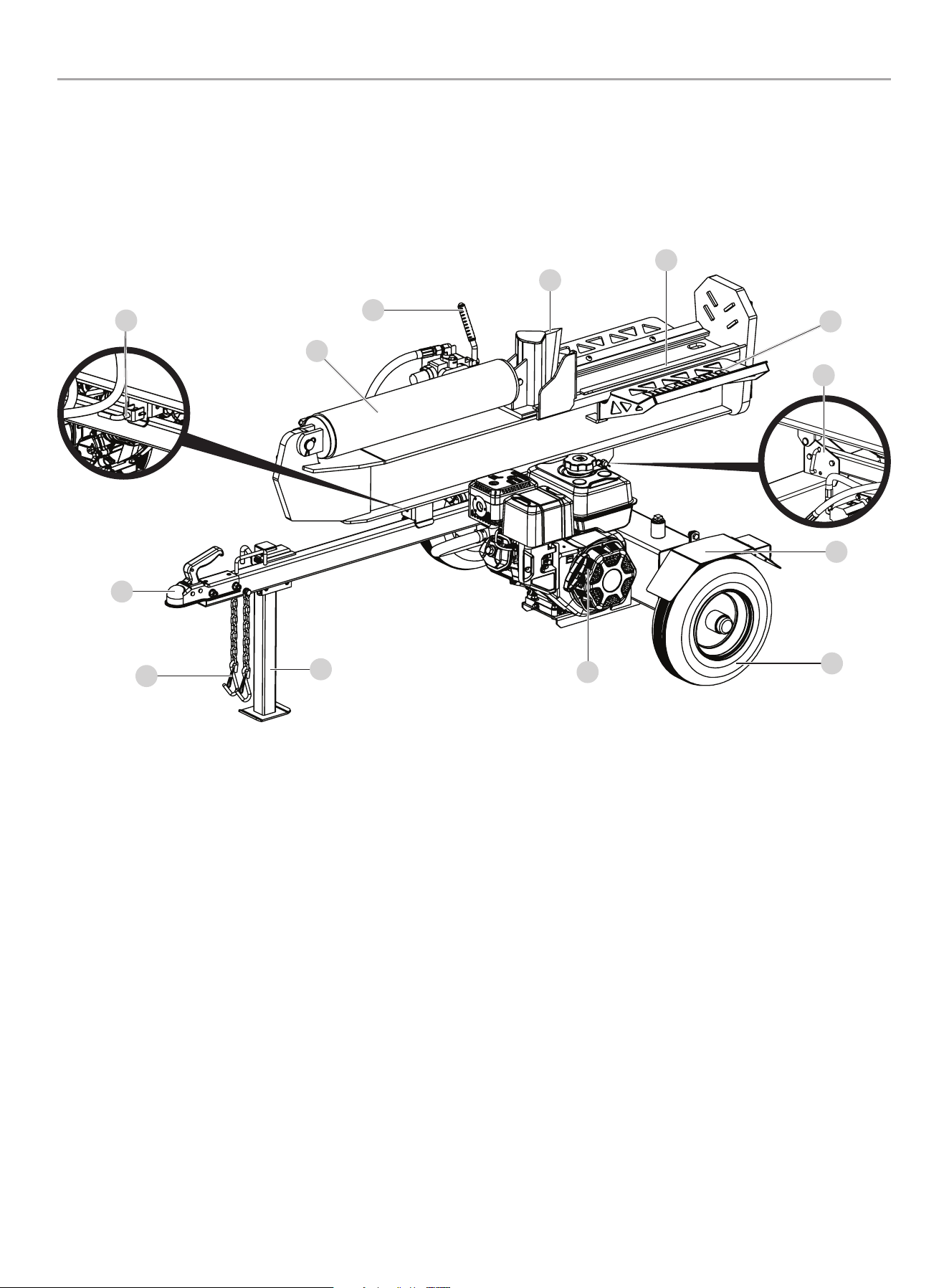
201519 - PARTIDOR DE TRONCOS DE 37 TONELADAS CON VIGA COMPLETA
CONTROLES Y CARACTERíSTICAS
14
CONTROLES Y CARACTERíSTICAS
Lea el manual del operador antes de operar el partidor de troncos. Familiarícese con la ubicación y función de los controles y
características. Conserve este manual como referencia para el futuro.
Partidor de Troncos
1. Seguro automático horizontal de la viga – Asegura la viga
en posición horizontal.
2. cilindro hidráulico – Apertura de 5 in. (12.7 cm) × carrera
de 23 in. (58.4 cm). MÁX de 3600 psi.
3. Mango de la válvula de control – Controla el movimiento de
la cuña cortante.
4. cuña
5. cuna de troncos – Evita que los troncos rueden fuera viga.
6. Receptor de troncos
7. Seguro rápido vertical de la viga – Asegura la viga en
posición vertical.
8. Guardabarros
9. Llantas – La velocidad máxima de remolque
45 MPH (72 KM/H).
10. Motor – 338cc, OHV.
11. pata de apoyo – Apoya el partidor de troncos durante la
operación. Suba la pata para remolcar la unidad.
12. cadenas de seguridad – Para usarlas durante el remolque.
13. Acoplador de remolque de 2 in. (5.1 cm) – Para remolcar el
partidor de troncos detrás de su vehículo.
3
2
13
12
6
11
10
9
8
4
5
7
1
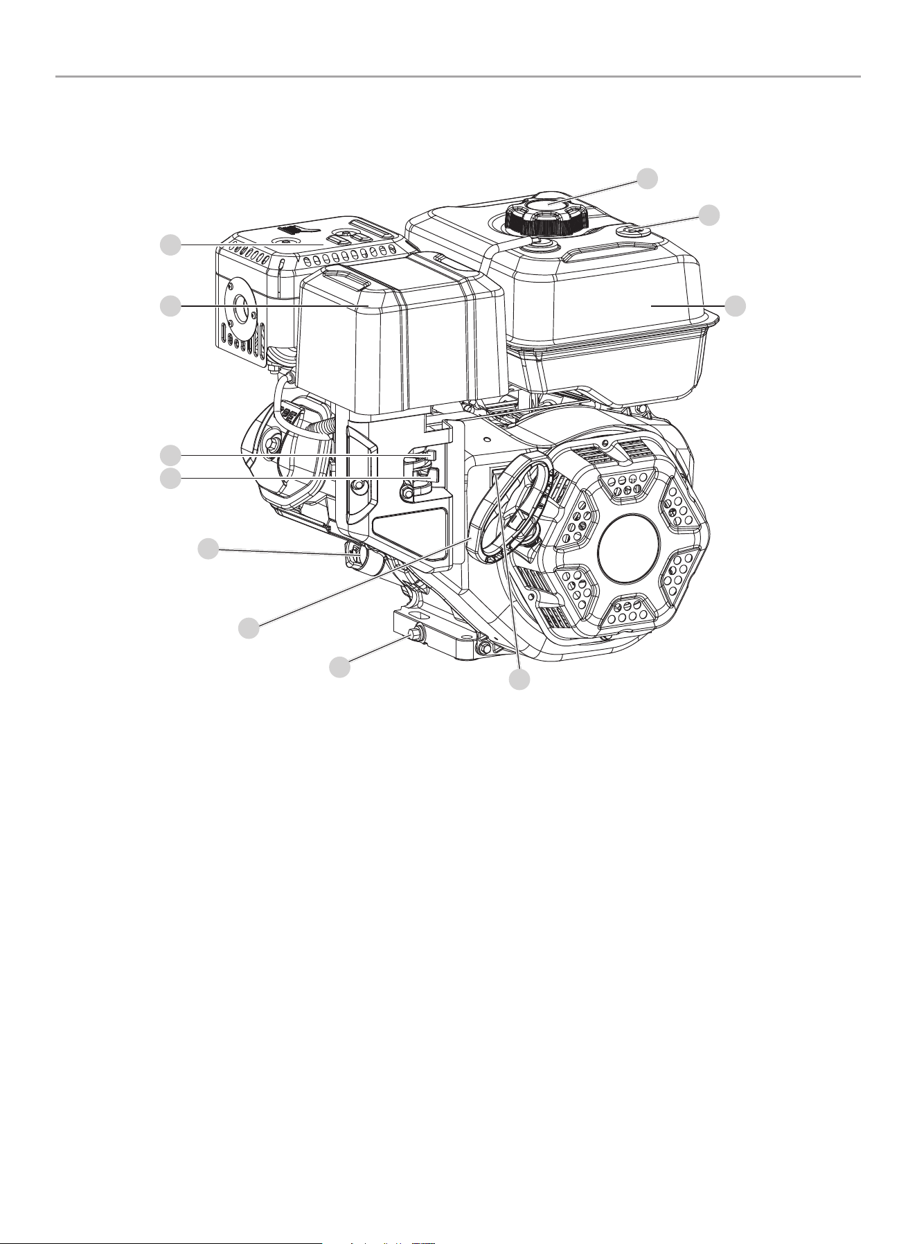
201519 - PARTIDOR DE TRONCOS DE 37 TONELADAS CON VIGA COMPLETA
CONTROLES Y CARACTERíSTICAS
15
1. Silenciador
2. Filtro de aire – Protege el motor filtrando el polvo y
escombros de la admisión de aire.
3. Ahogador – Utilizado para encender el motor.
4. Válvula de combustible – Utilizado para apagar o encender
el suministro de combustible.
5. Tapa de llenado/varilla de medición de aceite – Utilizado
para verificar y llenar el nivel de aceite.
6. Arrancador retráctil – Utilizado para encender el motor
manualmente.
7. perno de drenaje – Utilizado para drenar el aceite del motor.
8. interruptor del motor – Se utiliza para APAGAR el motor.
9. Tanque de gasolina – 1.45 gal. (5.5 L)
10. Medidor de gasolina
11. Tapa de combustible – Remueva para agregar combustible.
Motor
1
2
3
4
9
6
8
7
5
11
10

201519 - PARTIDOR DE TRONCOS DE 37 TONELADAS CON VIGA COMPLETA
CONTROLES Y CARACTERíSTICAS
16
Partes Incluidas
partes
ctd. de
piezas
Herramienta necesaria
ctd. de
Herramienta
Herramienta necesaria
Guardabarros 2
Perno M10x25 4 Llave o dado de 1x 16mm
Tuerca M10 4 Llave de 1x 17mm
Arandela de seguridad Ø10 4
Arandela plana Ø10 4
Ruedas 2
Tuerca de castillo 2 Llave de boca de 1x 30mm
Pasador chaveta Ø4 × 32 2 Pinzas de punta fina
Tapa del eje 2 Mazo
Barra de remolque 1
Perno M12x80 2 Llave o dado de 1x 18mm
Tuerca M12 2 Llave o dado de 1x 19mm
Arandela plana Ø12 2
Viga 1
Pasador del enganche 1
Pasador R 1
Motor 1
Perno M10x45 4 Llave de 1x 16mm
Contratuerca M10 4 Llave de 1x 17mm
Arandela plana Ø10 4
Manguera de succión 1 Abrazadera de manguera con resorte 2 Herramienta de abrazadera
Manguera de alta
presión
1 Anilla "O" Ø10 x 2.65 1 Llave abierta de 1x 27mm
Manguera de retorno
de aceite
1 Llave abierta de 1x 27mm
Receptores de troncos 2
Perno M10x20 4 Llave o dado de 16mm
Perno M10x30 2 Llave allen 1x 6mm
Tuerca M10 2 Llave de 1x 17mm
Arandela de seguridad Ø10 6
Arandela plana Ø10 6
Accesorios
– Aceite del motor
– Aceite hidraulíco
– Embudo para el aceite
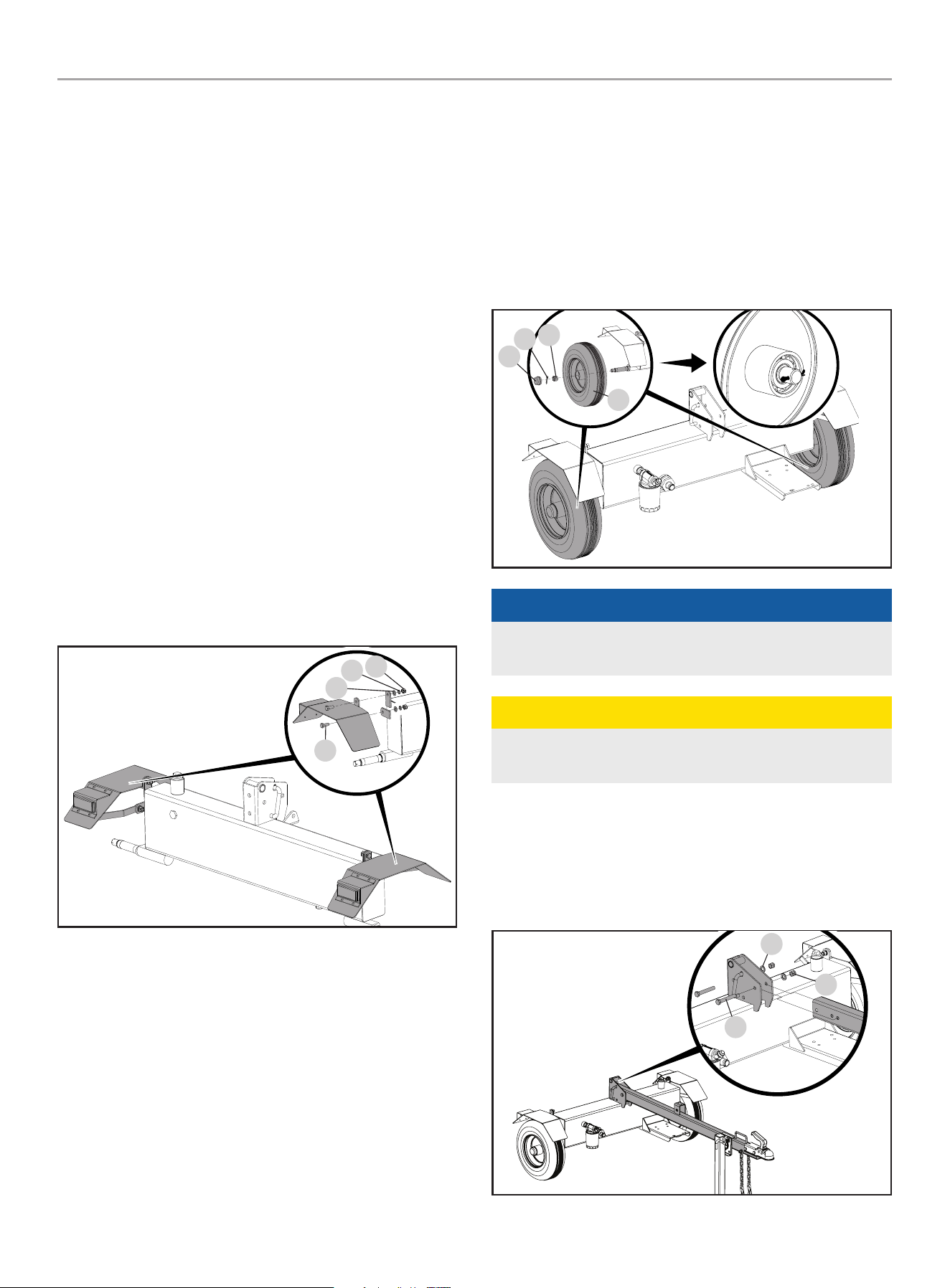
201519 - PARTIDOR DE TRONCOS DE 37 TONELADAS CON VIGA COMPLETA
MONTAjE
17
MONTAjE
Si su partidor de troncos ya está ensamblado, salte las
instrucciones de montaje.
Si no está ensamblado, por favor lea y siga estas instrucciones
siguientes.
Si tiene dudas acerca del montaje del partidor de troncos, llame
a nuestro Equipo de Apoyo Técnico al 1-877-338-0999. Tenga a
mano su número de serie y modelo.
Abra la Caja de Transporte
1. Coloque la caja de transporte sobre una superficie sólida,
plana.
2. Corte cuidadosamente las bandas de envío y retire la tapa de
la caja de trasporte.
3. Busque todas las piezas antes de comenzar el montaje.
1) Instale los Guardabarros
1. Fije el guardabarros al lado del tanque de aceite hidráulico
con un perno de M10 × 25 (A), arandela Ø10 (B), arandela
de seguridad Ø10 (C), y una tuerca M10 (D). El reflector de
seguridad debe estar orientado hacia la parte de atrás del
tanque de aceite hidráulico.
A
b
D
C
2. Repita estos pasos con el segundo guardabarros en el lado
opuesto.
2) Instale las Llantas
1. Retire las dos tapas de plástico de los cubos de las ruedas.
2. Deslice la rueda (A) sobre el eje.
3. Asegúrese de que el vástago de la válvula del neumático esté
orientado hacia afuera.
4. Enrosca la tuerca del castillo (B) en el eje y apriete a mano.
Use una llave inglesa para apretar otra vuelta de ¼.
5. Gire la rueda (A) para distribuir la grasa del rodamiento.
6. Afloje la tuerca del castillo (B) y vuelva a apretar a mano.
7. Instale el pasador (C) de cotter a través del eje y la tuerca del
castillo.
8. La rueda debe girar libremente, pero cuando se agarra a
ambos lados, no debe moverse de lado a lado (A).
9. Instale la tapa del eje (D) con un mazo de cara blanda o un
martillo y un bloque de madera.
10. Repita para la otra rueda.
D
b
C
A
AVISO
Durante el montaje mantenga tierra y desechos fuera de los
baleros.
PRECAUCIóN
El apretar excesivamente la tuerca castillo hará que los
cojinetes se calienten y fallen prematuramente.
3) Instale la barra de Remolque
Conecte la barra de remolque al soporte en la parte superior
del tanque de aceite hidráulico con dos pernos M12 × 80 (A),
arandelas planas Ø12 (B) y tuercas de bloqueo M12 (C).
A
b
C
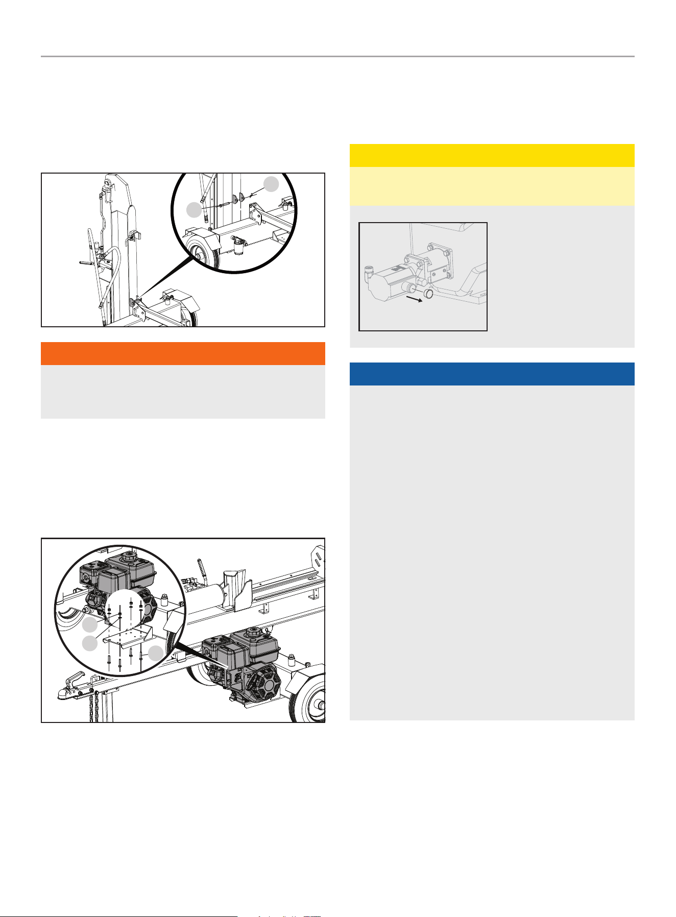
201519 - PARTIDOR DE TRONCOS DE 37 TONELADAS CON VIGA COMPLETA
MONTAjE
18
4) Instale la Viga
1. Coloque la viga vertical sobre la placa del pie.
2. Coloque el tanque en su posición para que los orificios de
pivote del tanque y la viga estén alineados.
3. Inserte el pasador (A) y asegúrelo con el pasador R (B).
A
b
ADVERTENCIA
La viga es muy pesada y siempre debe ser manejado con 2
o más personas. NO trate de levantar o manipular la viga sin
ayuda.
5) Instale el Motor
1. Coloque el motor en la plataforma de montaje del motor con
la cubierta de retroceso orientada hacia el exterior hacia la
rueda y alinee los 4 orificios de la base del motor con los
orificios de la plataforma del motor.
A
b
C
2. Instale un perno M10 × 45 (A) a través del orificio de la
plataforma del motor y a través del orificio de la base del
motor.
3. Coloque una arandela (B) en el perno M10 × 45 (A) y
enrosque una tuerca de bloqueo de nylon M10 (C) en el perno
y apriétela firmemente. Apriete a 8.8 lbf-ft – 10.3 lbf-ft (12-14
Nm) o completamente, y luego 1/4 de vuelta más.
4. Repita los pasos 2 y 3 para los pernos, arandelas y tuercas
de fijación restantes.
6) Instale la Manguera y el filtro Hidráulico
PRECAUCIóN
Tapones rojos de envío deben ser removidos de la bomba
hidráulica antes de instalar las mangueras.
La bomba hidráulica puede
contener residuo de aceite
de los procedimientos
de pruebas durante la
producción. Recomendamos
que use una bandeja para
aceite debajo de la bomba
antes de remover los
tapones de envío.
AVISO
Mangueras de entrada de aceite (alta presión) y retorno
de aceite
Algunas mangueras pueden ser preensambladas por la
fábrica, compruebe sus mangueras por debajo de las
instrucciones para asegurar el montaje adecuado.
– Estas mangueras son negras y tienen tuercas giratorias en
ambos extremos.
– La manguera de entrada de aceite envía aceite hidráulico
de la bomba al control de la válvula/cilindro.
– La manguera de retorno de aceite regresa el aceite
hidráulico del control de la válvula/cilindro hacia el tanque.
– Las conexiones de la manguera NO requieren cinta
selladora de rosca. El anillo en O sella contra la cara de los
acopladores de la bomba y la manguera.
Manguera de aspiración
– Esta es la manguera transparente que conecta el depósito
hidráulico a la entrada de la bomba.
– Asegure los dos extremos de la manguera con abrazaderas
para mangueras.
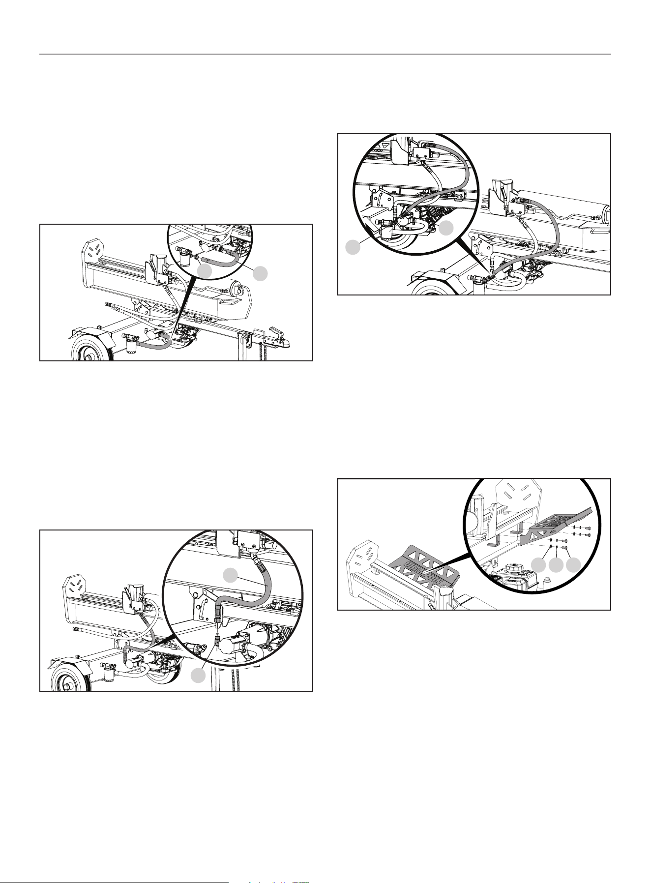
201519 - PARTIDOR DE TRONCOS DE 37 TONELADAS CON VIGA COMPLETA
MONTAjE
19
Manguera de succión
1. Utilizando las abrazaderas de manguera con resorte
proporcionadas, conecte un extremo de la manguera de
aceite transparente (A) al tanque de aceite hidráulico (B)
y el
otro extremo a la entrada de la bomba en la bomba (B).
Usando
un par de alicates, apriete las pestañas de las abrazaderas
de manguera cargadas por resorte para abrirlas y deslizarse
sobre el extremo de la manguera de succión transparente y el
accesorio de montaje y suelte los alicates para bloquear las
abrazaderas en su lugar.
A
b
Manguera de entrada de aceite (alta presión)
2. Coloque la junta tórica proporcionada en el accesorio de
salida de la bomba (C) como se muestra. Asegúrese de que la
junta tórica esté correctamente asentada en la ranura interior
del accesorio.
3. Enrosque el extremo suelto de la manguera hidráulica de alta
presión (D) en la salida de la bomba (C).
4. Apriete de forma segura el accesorio de la manguera con una
llave de 27 mm. Apriete a 44 lbf-ft - 52 lbf-ft (59.7-70.5 Nm).
D
C
Manguera de retorno de aceite (baja presión)
5. Enrosque el extremo suelto de la manguera hidráulica de baja
presión (E) en el accesorio hidráulico cónico en el tanque
de fluido hidráulico (F). Este accesorio de manguera solo
encajará en este accesorio para garantizar una conexión
correcta.
6. Apriete el accesorio de forma segura con una llave de 27 mm.
Apriete a 52 lbf-ft - 66 lbf-ft (70.5-89.5 Nm). Asegúrese de
que el ajuste, cuando esté completamente apretado, esté en
ángulo hacia arriba como se muestra.
E
f
7) Instale los Receptores de Troncos
Receptor de tronco grande (Lado de motor)
1. Con el receptor de troncos inclinado hacia arriba, alinee los
cuatro orificios en el receptor de troncos con los 4 orificios
roscados en el partidor de troncos.
2. Coloque arandelas planas Ø10 (A) y arandelas de seguridad
Ø10 (B) en los cuatro pernos M10 × 20 (C) y enrosque a
través de los orificios del receptor de troncos y en los orificios
de el partidor de troncos y aprietelos firmemente.
CbA
Receptor de tronco chico (lado de la manguera hidráulica)
3. Con el receptor de troncos inclinado hacia abajo y debajo del
borde de el partidor de troncos, alinee los dos orificios en el
receptor de troncos con los dos agujeros en el borde de la
viga.
4. Coloque los dos pernos M10 × 30 (D) a través de los orificios
de la viga y a través de los orificios en el receptor de troncos.
Coloque una arandela plana Ø10 (E) y una arandela de
seguridad Ø10 (F) en el perno del lado inferior y enrosque las
tuercas M10 (G) en los pernos y apriete firmemente.
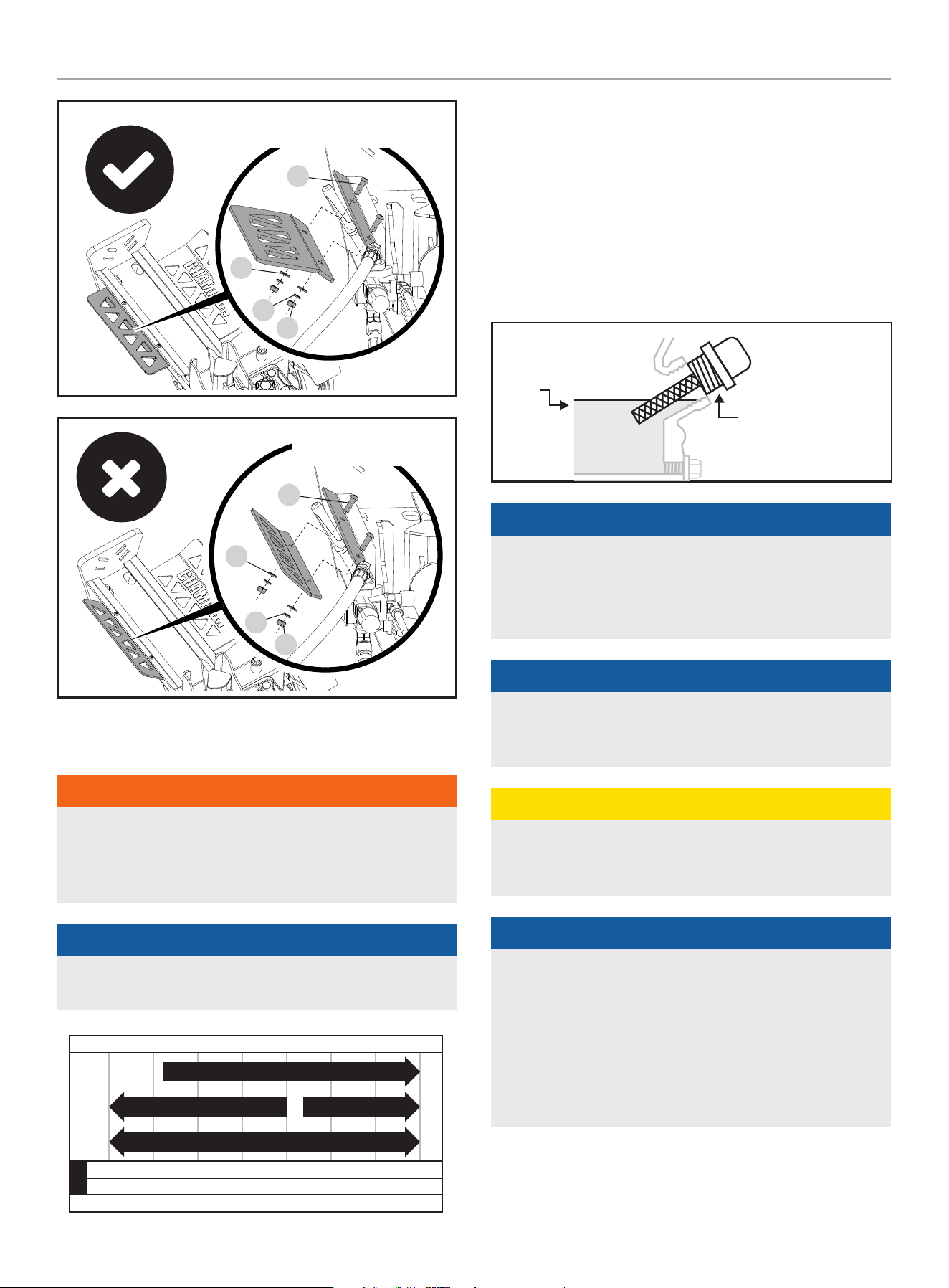
201519 - PARTIDOR DE TRONCOS DE 37 TONELADAS CON VIGA COMPLETA
MONTAjE
20
oRiEnTAciÓn dE MonTAJE
coRREcTA
D
E
f
G
oRiEnTAciÓn dE
MonTAJE incoRREcTA
D
E
f
G
Agregue Aceite del Motor
ADVERTENCIA
NO trate de encender o arrancar el motor sin antes haberlo
llenado correctamente con el tipo y cantidad de aceite
recomendado. Si el partidor de troncos resulta dañado por no
acatar estas instrucciones se anulará la garantía.
AVISO
El tipo de aceite recomendado es aceite 10W-30 de
automóvil.
-20 0 20 40 60
Temperatura de ambiente
Recomendación de Tipo de Aceite para Motor
80 100 120
-28.9
°F
°C -17.8 -6.7 4.4 15.6 26.7 37.8 48.9
10W-30
5W-30 Full Sintético Completo
10W-405W-30
1. Coloque el partidor de troncos en una superficie plana y
nivelada.
2. Retire la tapa de llenado/varilla de medición de aceite para
agregar el aceite.
3. Utilizando un embudo, agregue hasta 37.2 fl. oz (1100 ml)
(incluido) de aceite y reemplace la tapa de llenado/varilla de
medición de aceite. NO SOBRELLENE.
4. Revise diariamente el nivel del aceite y agregue según sea
necesario.
MAX
VARILLA DEL ACEITE
AVISO
Una vez que el aceite ha sido añadido, el nivel de aceite debe
estar 1-2 hilos por debajo del orificio de llenado.
Si se usa la varilla para comprobar el nivel de aceite,
NO atornille la varilla de medición durante la comprobación.
AVISO
Revise el aceite frecuentemente durante el período de
asentamiento. En la sección Mantenimiento encontrará los
intervalos de servicio recomendados.
PRECAUCIóN
El motor viene equipado con una válvula de corte y se
detendrá cuando el nivel del aceite en el cigüeñal esté por
debajo del valor umbral.
AVISO
Consideramos que las primeras 5 horas de tiempo de función
son el período de asentamiento para el motor. Durante el
período de asentamiento se recomienda utilizar mezclas de
aceites no sintéticos de automóviles. Después del período de
asentamiento el lubricante sintético se puede utilizar, pero no
es necesario. Evite correr el motor a una baja velocidad y evite
el funcionamiento prolongado a un RPM constante. Después
del período de asentamiento de 5 horas, cambie el aceite.
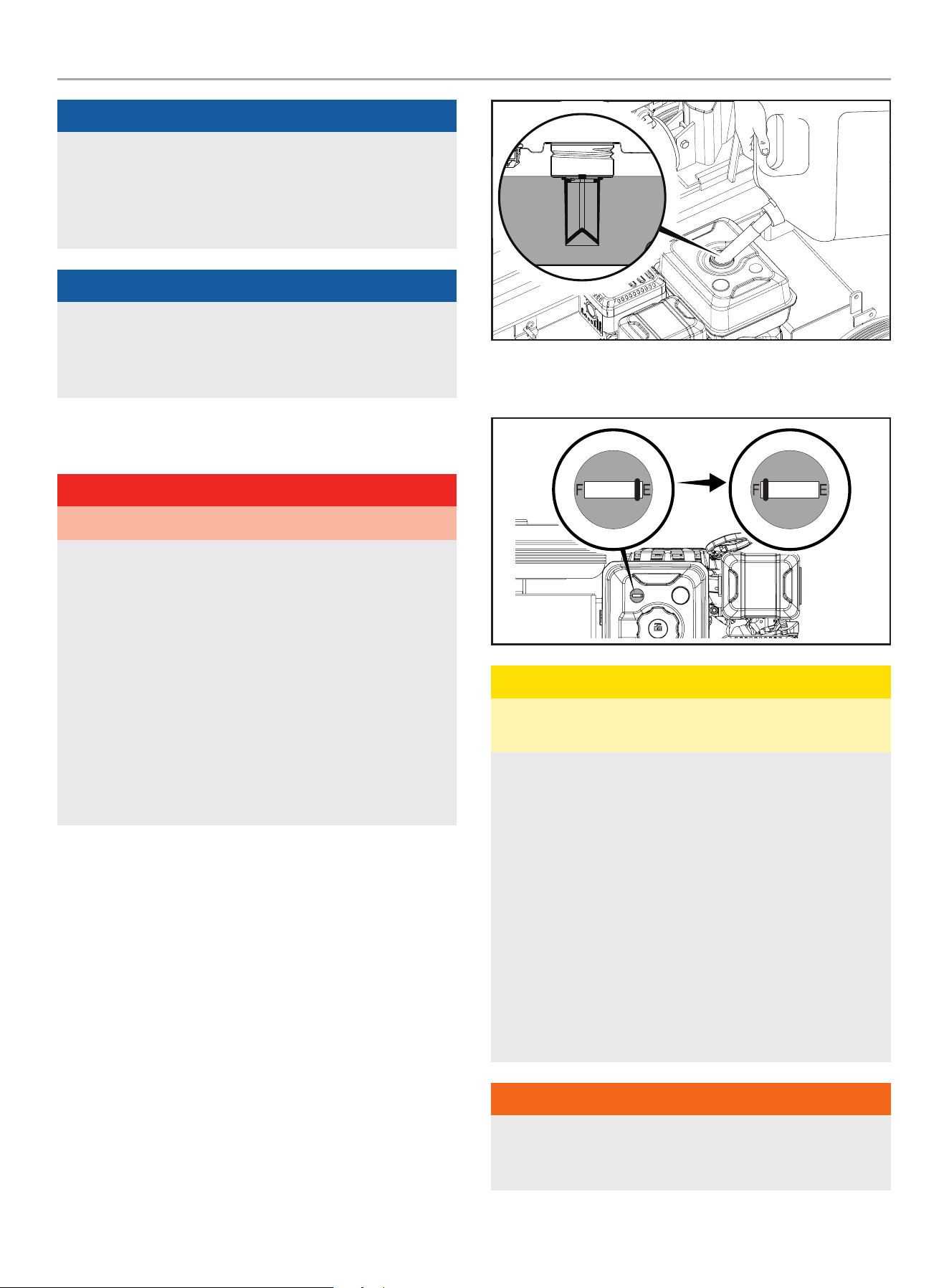
201519 - PARTIDOR DE TRONCOS DE 37 TONELADAS CON VIGA COMPLETA
MONTAjE
21
AVISO
El aceite sintético se puede utilizar después de las 5 horas
iniciales del período de asentamiento. Uso de aceite sintético
no disminuir el intervalo de cambio de aceite recomendado.
Aceite sintético 5W-30 ayudará a encender en temperaturas
ambientales frías < 41ºF (5ºC).
AVISO
El tiempo va a afectar rendimiento del aceite del motor y del
motor. Cambie el tipo de aceite de motor usado en base a
las condiciones climáticas en función de las necesidades del
motor.
Agregue Combustible
PELIGRO
Vapores de gasolina son altamente inflamables y explosivos.
NO encienda ni fume cigarrillos. El fuego o la explosión pueden
causar quemaduras graves o la muerte.
Siempre llene o drene el combustible al aire libre en un
área bien ventilada. NO bombee gasolina directamente en
el partidor de troncos. Utilice un contenedor aprobado para
transferir el combustible al partidor de troncos.
Nunca use un contenedor de gasolina, un tanque de gasolina o
cualquier otro artículo de combustible que esté roto, cortado,
roto o dañado.
NO llene en exceso el tanque de gasolina. Mantenga siempre
el combustible alejado de chispas, llamas abiertas, luces
piloto, calor y otras fuentes de ignición.
Use gasolina, limpia y fresca regular sin plomo con un octanaje
mínimo de 87 y un contenido de etanol de menos de 10% en
volumen. ybc
NO mezcle aceite con gasolina.
1. Retire la tapa de gasolina.
2. Agregue gasolina al tanque lentamente. NO SOBRE LLENE. El
combustible se puede expandir después del llenado.
Se requiere que deje un mínimo de ¼ in. (6.4 mm) de
espacio en el tanque para la expansión del combustible,
aunque se recomienda más de ¼ in. (6.4 mm). La gasolina
puede ser forzado a salir del depósito como resultado de la
expansión si se llena de más y eso puede afectar al estado de
funcionamiento estable del producto.
3. El nivel aproximado de combustible se demuestra en el
medidor de combustible en la parte de arriba del tanque.
Vacío Lleno
PRECAUCIóN
Use gasolina normal sin plomo de 87 octanos como mínimo y
contenido de etanol de menos de 10% por volumen.
NO encienda ni fume cigarrillos al llenar el tanque.
NO mezcle el aceite con la gasolina.
Llene el tanque hasta aproximadamente ¼ in. (6.4 mm)
por debajo de la parte superior del mismo para permitir la
expansión del combustible.
NO bombee gasolina directamente al partidor de troncos
en la estación de servicio. Use un recipiente aprobado para
transferir la gasolina al partidor de troncos.
NO llene el tanque en interiores.
NO llene el tanque cuando el motor esté funcionando o esté
caliente.
NO rebose el tanque.
ADVERTENCIA
Si la gasolina se vierte demasiado rápido a través del filtro de
combustible, puede ocasionar un retroceso de gasolina hacia
el operador mientras se está cargando.
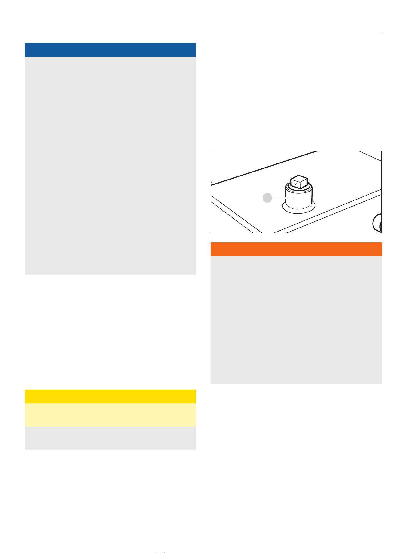
201519 - PARTIDOR DE TRONCOS DE 37 TONELADAS CON VIGA COMPLETA
MONTAjE
22
AVISO
El motor trabaja bien con gasolina con mezcla de etanol de
10% o menos. Cuando utilice mezclas de gasolina-etanol es
conveniente tener en cuenta algunas cuestiones:
– Las mezclas de etanol-gasolina pueden absorber más
agua que la gasolina sola.
– Estas mezclas de etanol pueden llegar a separarse al final,
dejando agua o un barro acuoso en el tanque, en la válvula
de combustible y en el carburador. Este combustible
modificado puede llegar al carburador y causar daños al
motor y/o crear riesgos potenciales.
– Si se utiliza estabilizador de combustible, confirme que
esté formulado para trabajar con combustibles con mezcla
de etanol.
– Todo daño o riesgo causado por gasolina con mezcla de
etanol mayor a 10% por volumen, gasolina almacenada
incorrectamente y/o estabilizadores formulados
indebidamente no quedan cubiertos por la garantía del
fabricante.
Se aconseja siempre cerrar el suministro de combustible y
hacer funcionar el motor hasta que se agote el combustible en
cada uso. Vea las instrucciones de Almacenamiento para un
periodo extendido sin uso.
Agregue Aceite Hidráulico
Si su partidor de troncos fue entregado pre-ensamblado, siga
las siguientes instrucciones:
1. Posicione el partidor de troncos en una superficie plana y
nivelada.
2. Remueva el tapón de plástico de envío del tanque de aceite
encima del tanque (A) y deséchelo. Reemplace con el tapón
de acero de aceite (con orificio de ventilación) que fue
enviado con su partidor de troncos (A).
PRECAUCIóN
No opere el partidor de troncos con el tapón de envío
temporal.
Presión aumentará adentro del tanque y un daño potencial
puede ocurrir.
3. Después de operar y circular la unidad varios minutos
(purgando aire del sistema), apague el motor y verifique
el nivel del aceite hidráulico usando la mirilla del aceite.
El nivel de aceite deberá visiblemente llenar la mirilla.
Si su partidor de troncos se entrego sin ensamblarse,
siga las siguientes instrucciones:
1. Cerciórese de que el partidor de troncos esté en una
superficie plana y nivelada.
2. Retire del tanque el tapón de llenado de aceite (A).
3. Agregue 5 gal. (18.9 L) de aceite hidráulico – consulte
la sección de especificaciones para los tipos de aceite
aceptable.
4. Revise el nivel del aceite hidráulico mediante la mirilla. El
nivel de aceite debe llenar visiblemente la mirilla de vidrio.
A
ADVERTENCIA
NO quite el tapón de llenado de aceite hidráulico con el motor
en marcha o caliente. El aceite caliente puede escapar y
causar quemaduras graves. Siempre deje que el partidor de
troncos se enfríe completamente antes de quitar el tapón del
aceite hidráulico.
La alta presión del líquido y las temperaturas se crean en
los partidores de registro hidráulico. El líquido hidráulico se
escapará a través de una abertura minúscula y puede perforar
la piel y causar una intoxicación severa de sangre.
Inspeccione periódicamente el sistema hidráulico de posibles
fugas. No busque fugas con la mano mientras el sistema está
presurizado. Busque atención médica de inmediato si recibe
una herida por escape de líquidos.
5. Vuelva a colocar y a apretar el tapón de aceite y oriente el
orificio de ventilación en dirección contraria a la zona del
operador.
6. Arranque el motor. (Vea la sección de encendiendo el motor)
7. Extienda y retraiga la cuña para purgar el aire del sistema
hidráulico. Cuando el movimiento de la cuña sea suave,
el sistema estará debidamente purgado.
8. Revise la mirilla en el tanque de aceite hidráulico. Agregue
aproximadamente 1 galón (3.8 L) de aceite hidráulico hasta el
nivel de la mirilla. NO sobrellene.
9. Revise diariamente el nivel del aceite y agregue según sea
necesario.

201519 - PARTIDOR DE TRONCOS DE 37 TONELADAS CON VIGA COMPLETA
MONTAjE
23
AVISO
Cuando la temperatura exterior sea inferior a 32˚F (0˚C), líquido
de transmisión Dexron III se puede utilizar. No mezcle aceite
hidráulico y el líquido de transmisión. Vacié todo el aceite o
fluido antes de agregar el otro.
Vea la sección de Especificaciones del sistema del aceite
hidráulico para mas detalles.
AVISO
Para verificar el nivel de aceite, use la mirilla de aceite en el
tanque. La mirilla del aceite tiene un indicador para el nivel
aceptable de aceite. Si el aceite esta debajo del indicador,
agregue aceite como sea necesario. NO SOBRELLENE.
Inspeccione el Partidor de Troncos Antes de
Cada Uso
1. Revise el nivel del aceite hidráulico e inspeccione visualmente
todas las mangueras, aditivos y el cilindro por conexiones
flojas, fugas presentes, grietas, picaduras u otro tipo de daño.
2. NO opere el partidor de troncos si hay indicios de daños o
residuos aceitosos.
3. Revise el motor y cerciórese de que el nivel del aceite
esté correcto antes de operarlo. Si el motor viene con un
parachispas, límpielo e inspecciónelo regularmente (siga el
programa de mantenimiento del parachispas).
4. Las llantas deben estar plenamente inflados y en buen
estado. En la superficie lateral de las llantas encontrará su
presión recomendada.
ADVERTENCIA
NO infle excesivamente las llantas. Puede resultar gravemente
lesionado si explotan.
NO remolque el partidor de troncos si las llantas están
desgastados o no retienen el aire.
NO exceda la velocidad máxima de remolque de
45 MPH (72 KM/H).
Cambiando la Viga de Orientación Horizontal
a Vertical
Cuando los troncos son demasiado pesados para levantar, la viga
del partidor de troncos puede moverse de orientación horizontal a
vertical.
Para cambiar la orientación de horizontal a vertical:
1. Bloquee las ruedas para evitar que la unidad ruede.
2. Tire del pasador cargado por resorte en la cerradura de viga
horizontal unida a la barra de remolque para liberar la viga.
De pie junto al ariete hidráulico, (lado opuesto del motor)
agarre firmemente el mango de la viga y levántelo hacia
arriba mientras empuja la viga hacia atrás hasta que esté
erguida. (Precaución, la viga esta pesada).
3. Extraiga el pasador de seguro rápido cargado por resorte y
gírelo alrededor de la posición de las 9 en punto alrededor del
borde en la viga para asegurarlo en la posición vertical.
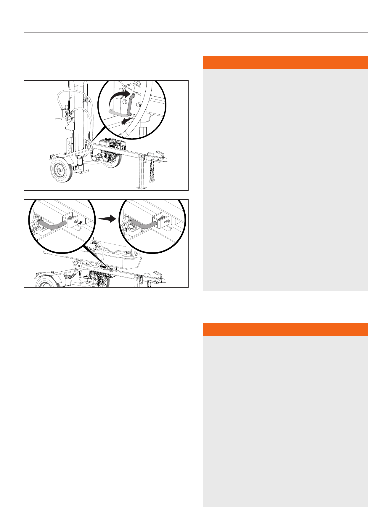
201519 - PARTIDOR DE TRONCOS DE 37 TONELADAS CON VIGA COMPLETA
MONTAjE
24
4. Para cambiar de orientación vertical a horizontal, invierta los
pasos. El viga se bloqueará automáticamente en el seguro
automático en la barra de remolque cuando se baje a su
posición.
Remolque Seguro del Partidor de Troncos
ADVERTENCIA
1. Compruebe siempre las regulaciones locales, estatales
o provinciales con respecto a remolque, licencias y luces
antes de remolcar su partidor de troncos. Revise las
advertencias de seguridad de remolque en el manual del
vehículo de remolque.
2. Antes de remolcarlo cerciórese de que el partidor de
troncos esté correctamente y firmemente unido al
vehículo y que las cadenas de seguridad tengan suficiente
huelgo para permitir las vueltas.
3. Antes del transporte, compruebe SIEMPRE que la válvula
de combustible está CERRADA y que el tanque de
combustible está vacío.
4. La pata de apoyo debe estar fija en la posición “arriba”
para remolcar.
5. Si utiliza una cubierta para el partidor de troncos, quítela
SIEMPRE antes de remolcar el partidor de troncos.
6. Nunca exceda la velocidad máxima de 45 mph (72 km/h).
El remolcar el partidor a velocidades superiores a 45 mph
(72 km/h) podría causar lesiones graves o letales.
Siempre ajuste la velocidad de remolque según el terreno
y las condiciones.
7. Antes de operar el partidor de troncos, siempre
desconéctelo del remolque.
Ubicación del Partidor de Troncos
ADVERTENCIA
SiEMpRE utilice la partidor de troncos al aire libre.
NUNCA coloque ni utilice la partidor de troncos cerca de
ventanas, puertas, rejillas de ventilación, tomas de aire u
otras aberturas por donde los gases venenosos del escape del
motor puedan entrar en los espacios ocupados del edificio.
Mantenga siempre una distancia mínima de 5 pies (1.5 m) de
la vegetación combustible seca para evitar incendios cuando
utilice este partidor de troncos.
Deje siempre un mínimo de 3 pies (0.9 m) de espacio libre
en todos los lados del partidor de troncos para permitir
un funcionamiento seguro, una refrigeración adecuada, el
mantenimiento y las revisiones.
Coloque siempre el partidor de troncos sobre una superficie
firme y nivelada para asegurar una buena base de apoyo.
NO trabaje sobre barro, hielo, hierba alta, maleza o nieve.
SIEMPRE opere el partidor de troncos alrededor de la zona de
trabajo como se muestra a continuación.
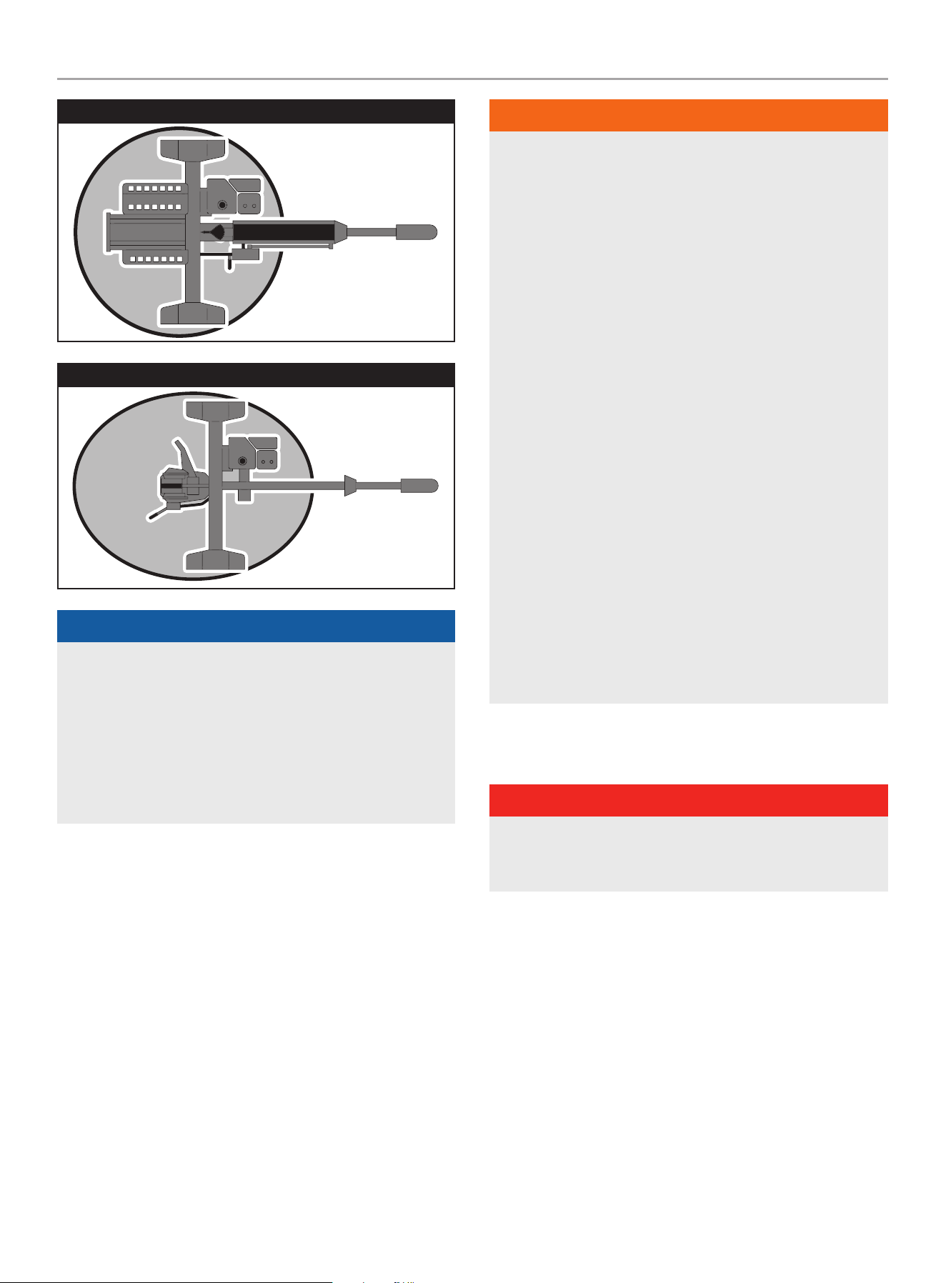
201519 - PARTIDOR DE TRONCOS DE 37 TONELADAS CON VIGA COMPLETA
OPERACIóN
25
poSiciÓn dE FuncionAMiEnTo HoRiZonTAL
A
R
E
A
D
E
T
R
A
B
A
J
O
poSiciÓn dE FuncionAMiEnTo VERTicAL
A
R
E
A
D
E
T
R
A
B
A
J
O
AVISO
para operación vertical:
– Quite el pasador de seguridad de la viga del soporte de la
misma.
– Use el mango en el cilindro para hacer girar la viga hacia
una posición vertical.
– Inserte el pasador de seguridad de la viga en el soporte
pivotante.
ADVERTENCIA
SIEMPRE use el partidor de troncos para lo que está diseñado.
El partidor debe usarse siempre para cortar troncos, a lo largo
con el grano.
NUNCA modifique, cambie los ajustes del motor, las
velocidades de funcionamiento, los ajustes de presión ni
realice otros cambios en el partidor de troncos. Cualquier
modificación podría causar daños materiales, lesiones
personales graves o la muerte y anulará la garantía del
fabricante.
NUNCA conecte una soga, cable ni ningún dispositivo a la
palanca de control del partidor.
SIEMPRE opere el partidor de troncos con luz de día.
NUNCA opere, ni deje a nadie operar, el partidor de troncos
mientras esté bajo la influencia del alcohol, drogas o
medicamentos.
NUNCA deje el partidor solo mientras el motor esté
funcionando.
NO cambie la posición de corte con el motor funcionando. El
contacto con el silenciador caliente puede causar quemaduras
graves.
Siempre cerciórese de que la viga esté en la posición trabada.
NO deje caer la viga, ya que podría causar lesiones personales
graves, aplastar los dedos, las manos o dañar el partidor de
troncos.
OPERACIóN
PELIGRO
SIEMPRE opere el partidor de troncos a la intemperie alejado
de inmuebles, ventanas, puertas, y tapas de ventilación para
admisiones.
Encendido del Motor
1. Asegúrese de que el partidor de troncos esté en una
superficie plana y nivelada.
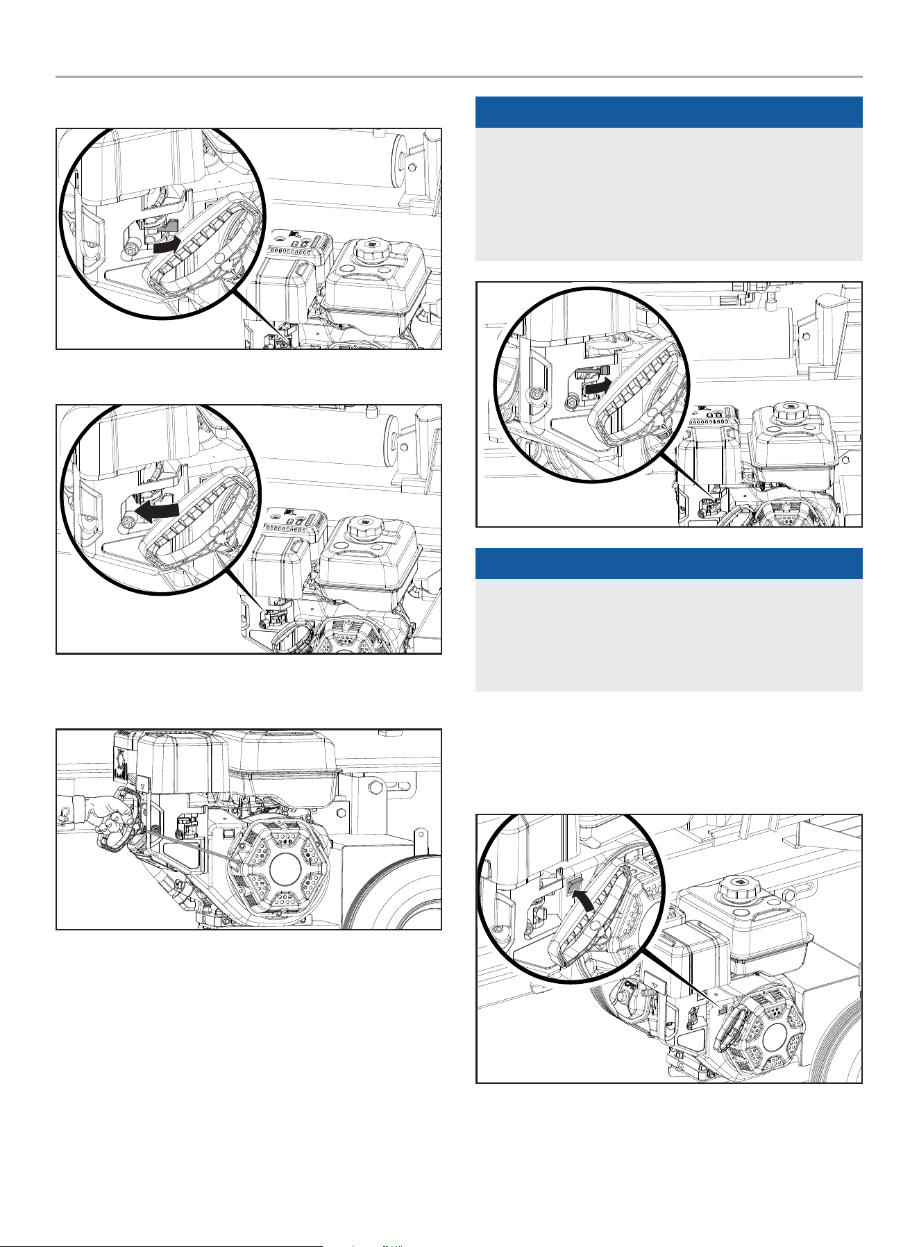
201519 - PARTIDOR DE TRONCOS DE 37 TONELADAS CON VIGA COMPLETA
OPERACIóN
26
2. Gire la válvula de combustible a la posición “ENCENDIDO”.
3. Mueva la palanca del ahogador a la posición “AHOGAR”.
4. Tire del cable de arranque hasta que se sienta la resistencia y
luego tire rápidamente.
5. A medida que el motor se calienta, mueva la palanca del
ahogador a la posición “CORRER”.
AVISO
Mantenga la palanca del ahogador en la posición “AHOGAR”
por 2 jalones de la cuerda de arranque. Después del segundo
jalón, mueva la palanca a la posición “CORRER” hasta los
próximos 3 jalones de la cuerda de arranque. El exceso de
ahogo provoca falla en la bujía / inundación del motor debido a
la falta de aire entrante. Esto hará que el motor no arranque.
AVISO
Si el motor enciende pero no corre asegure que el partidor
de troncos esta en una superficie plana y nivelada. El motor
esta equipado con un sensor de bajo nivel de aceite que va a
prevenir que el motor corra cuando el nivel de aceite este por
debajo de un umbral critico
Parada del Motor
En caso de emergencia, oprima el interruptor del motor a la
posicion “ApAGAdo”.
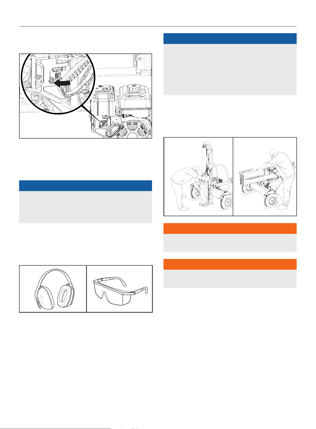
201519 - PARTIDOR DE TRONCOS DE 37 TONELADAS CON VIGA COMPLETA
OPERACIóN
27
En funcionamiento normal:
1. Gire la válvula de combustible a la posición “APAGADO”.
2. Deje el motor en marcha hasta que la falta de combustible
haya detenido el motor. Esto usualmente toma unos minutos.
importante: Siempre asegurese que la válvula de combustible
esté a la posición “APAGADO” cuando el motor no está en uso.
AVISO
Si el motor no se va a utilizar durante un período de dos
(2) semanas o más, sírvase remitirse a la sección de
Almacenamiento para proceder al adecuado almacenamiento
del motor y del combustible.
Operación del Partidor de Troncos
1. SIEMPRE use protección auditiva y ocular, ropa protectora y
equipo de seguridad.
2. Bloquee las llantas y coloque ambas patas de apoyo en la
posición de ABAJO para impedir movimientos accidentales
del partidor durante la operación.
3. Fije el partidor de troncos en posición horizontal o vertical.
AVISO
La posición HORIZONTAL se usa para troncos más livianos que
pueden cargarse fácilmente en la viga.
La posición VERTICAL se usa para troncos livianos al igual que
pesados que presentan dificultad para cargarlos en la viga.
El no emplear técnicas de elevación de troncos correctas
puede causar lesiones lumbares.
4. Cargue un tronco en la viga contra la placa extrema
(LARGO MÁX. DEL TRONCO – 24 in. [61 cm])
5. Para estabilizar el tronco, coloque la mano izquierda en el
lado del tronco.
Vertical
Horizontal
ADVERTENCIA
Nunca coloque la mano en los extremos del tronco, entre la
placa de tronco y final o el tronco y la cuña de cortar.
ADVERTENCIA
Solo se permite un operador. El adulto que carga y estabiliza el
tronco, debe ser la persona que opera el mango del control.
6. Asegúrese de que todas las extremidades estén libres de
zonas de aplastamiento.
7. Utilice la mano derecha para empujar la manija de la válvula
de control hacia adelante (hacia la placa final) para dividir el
tronco.
8. Retire la mano izquierda del tronco una vez que la cuña
comience a ponerse en contacto con el tronco. Continúe
manteniendo el controlador en la posición de avance hasta
que el tronco se divida.
9. Empuje la manija de la válvula de control automático hacia
atrás para devolver la cuña a su posición original.
10. Despeje la madera partida de la zona de trabajo.

201519 - PARTIDOR DE TRONCOS DE 37 TONELADAS CON VIGA COMPLETA
MANTENIMIENTO
28
AVISO
Es normal que el fluido hidráulico se vuelva espumoso /
burbujeante durante el funcionamiento. Esto puede ser
causado por el aceite agitado en el tanque de recogida de aire.
AVISO
Si un tronco se atasca, queda incrustado o no se parte
completamente, empuje el mango de control hacia atrás y deje
que el partidor de troncos retire el tronco de la cuña.
Quite los desechos de la viga, la cuña y la placa extrema.
AVISO
La carrera del cilindro está diseñado para que la cuña se
detenga aproximadamente 1.5 in. (3.8 cm) de la placa en el
final de la viga.
Operación a Gran Altura
La densidad del aire a elevada altitud es menor que a nivel del
mar. La potencia del motor se reduce a medida que disminuyen la
masa de aire y la relación aire-combustible. La potencia del motor
y la salida del partidor de troncos se reducirán aproximadamente
un 3½% por cada 1000 pies de elevación sobre el nivel del mar.
Esto es una tendencia natural y no puede cambiarse ajustando
el motor. A altitudes elevadas también pueden producirse altas
emisiones de escape debido al mayor enriquecimiento de la
relación aire-combustible. Entre otros problemas de elevada
altitud pueden incluirse arranque difícil, mayor consumo de
combustible y fallas en las bujías.
Para solucionar problemas de elevada altitud que no sean la
pérdida natural de potencia, CPE puede proporcionar un surtidor
principal de carburador para elevada altitud. El surtidor principal
alternativo e instrucciones de instalación pueden ser obtenidos al
comunicarse con nuestro Equipo de Apoyo Técnico. Instrucciones
de instalación están disponibles también en el Boletín Técnico
(Technical Bulletin) en el sitio web de CPE.
El número y altura mínima recomendada para la aplicación del
surtidor principal del carburador para altitud elevada están
detallados en la tabla de abajo.
Para escoger el surtidor principal de altura correcto, es necesario
identificar el modelo del carburador. A estos fines, hay un código
estampado a lado del carburador. Seleccione el número correcto
del repuesto del surtidor principal correspondiente al código del
carburador que se encuentra en su carburador particular.
código del
carb.
número de parte del
Surtidor de Altitud
Elevada
Altitud Mínima
16100-
000047
16161-000039
3000-6000 ft.
(914.4-1828.8 m)
16161-000038
6000-8000 ft.
(1828.8-2438.4 m)
ADVERTENCIA
La operación con el surtidor principal alternativo a elevaciones
inferiores a las mínimas recomendadas puede dañar el motor.
Para operaciones a elevaciones inferiores, debe usarse el
surtidor principal estándar. Hacer funcionar el motor con la
configuración incorrecta a una altitud dada puede aumentar
sus emisiones y disminuir la eficiencia y el rendimiento del
combustible.
MANTENIMIENTO
Cerciórese de mantener el partidor de troncos limpio y
correctamente almacenado. Siempre opere la unidad en una
superficie plana y nivelada en un entorno limpio y seco. NO
exponga la unidad a condiciones extremas, polvo excesivo, tierra,
humedad o vapores corrosivos. Revise todos los orificios y ranuras
de ventilación para cerciorarse de que estén limpios y despejados.
Limpia el apagachispas cada 100 horas.
Compruebe y apriete todos los pernos y tuercas antes de operar el
partidor de troncos.
ADVERTENCIA
Nunca opere un partidor de troncos dañado o defectuoso.
ADVERTENCIA
Mantenimiento inapropiado anulará su garantía.
AVISO
Para sistemas y dispositivos de control de emisiones, lea
y comprenda sus responsabilidades para servicios como
se declara en la declaración de la garantía de control de
emisiones en este manual.
El propietario/operador es responsable por todo el mantenimiento
periódico.
Complete oportunamente todo el mantenimiento programado.
Corrija todos los problemas antes de operar el partidor de troncos.
Para obtener asistencia de servicio o repuestos, llame a nuestro
Equipo de Apoyo Técnico al 1-877-338-0999.
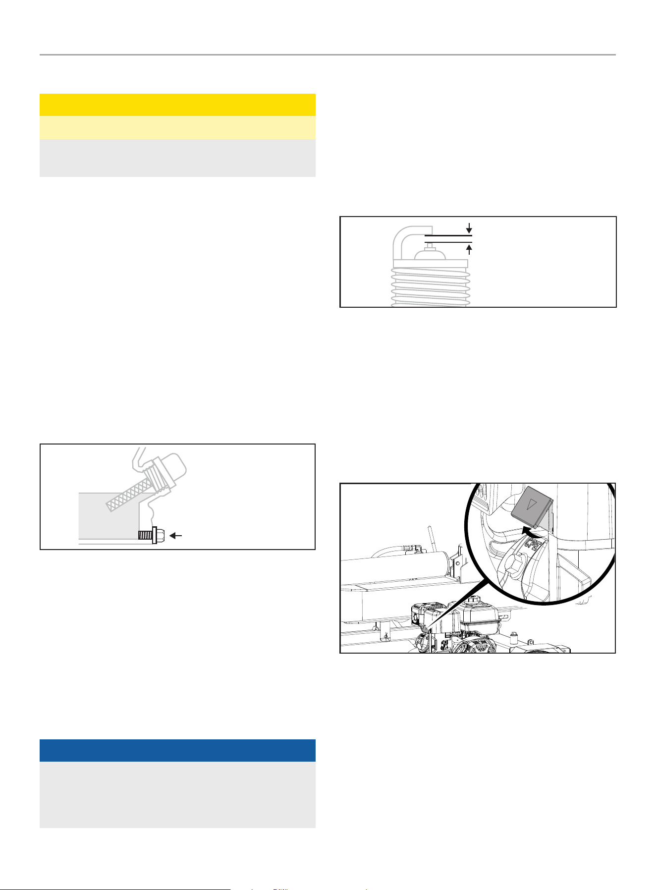
201519 - PARTIDOR DE TRONCOS DE 37 TONELADAS CON VIGA COMPLETA
MANTENIMIENTO
29
Limpiando el Partidor de Troncos
PRECAUCIóN
NO rocíe el motor con agua.
El agua puede ingresar al motor por las ranuras de ventilación
y dañar el motor.
Limpie los escombros de la viga, cuña y placa final.
Use un paño húmedo para limpiar las superficies exteriores del
motor y el partidor de troncos.
Use un cepillo de cerdas suaves para eliminar la suciedad y
el aceite. Use un compresor de aire (25 PSI) para despejar la
suciedad y los desechos del motor. Limpie todas las piezas
metálicas con un trapo aceitado para evitar la oxidación y la
corrosión.
Cambiando el Aceite del Motor
Cambie el aceite cuando el motor esté tibio. Consulte las
especificaciones de aceite para seleccionar el aceite adecuado
según su entorno de operación.
1. Retire el tapón de drenaje de aceite con un dado de 12 mm
(no incluido) y una extensión.
PERNO DE DRENAJE
2. Deje que el aceite se drene completamente adentro de un
recipiente apropiado.
3. Vuelva a colocar el tapón.
4. Retire la tapa de llenado/varilla indicadora de aceite para
agregar el aceite.
5. Agregue aceite en acuerdo con Agregue Aceite de Motor en
la sección de Montaje. NO SOBRELLENE. El aceite para el
mantenimiento rutinario no esta incluido.
6. Deseche el aceite usado en una planta aprobada para el
tratamiento de desechos.
AVISO
Una vez que el aceite ha sido añadido al motor, el nivel de
aceite debe ser de 1-2 hilos por debajo del orificio de llenado.
Si se usa la varilla para comprobar el nivel de aceite, NO
atornille la varilla de medición durante la comprobación.
Limpiando y Ajustando las bujías
1. Retire el cable de la bujía de la bujía.
2. Use una herramienta para bujías (no incluida), o un dado de
13/16 in. (21 mm) (no incluido) para remover la bujía.
3. Revise el electrodo en la bujía. Debe estar limpio y no
desgastado para producir la chispa de encendido.
4. Cerciórese de que la abertura de la bujía sea de
0.028-0.031 in. (0.7-0.8 mm).
ESPACIO DE LA BUJÍA
5. Al reemplazarla, refiérase a Especificaciones para los tipos de
bujías.
6. Instale firmemente de nuevo la bujía.
7. Conecte el cable de la bujía a la bujía.
Limpiando el filtro de Aire
1. Con los dedos, levante la pestaña un poco y levante la tapa
del filtro de aire por encima de la posición de cierre de la
pestaña.
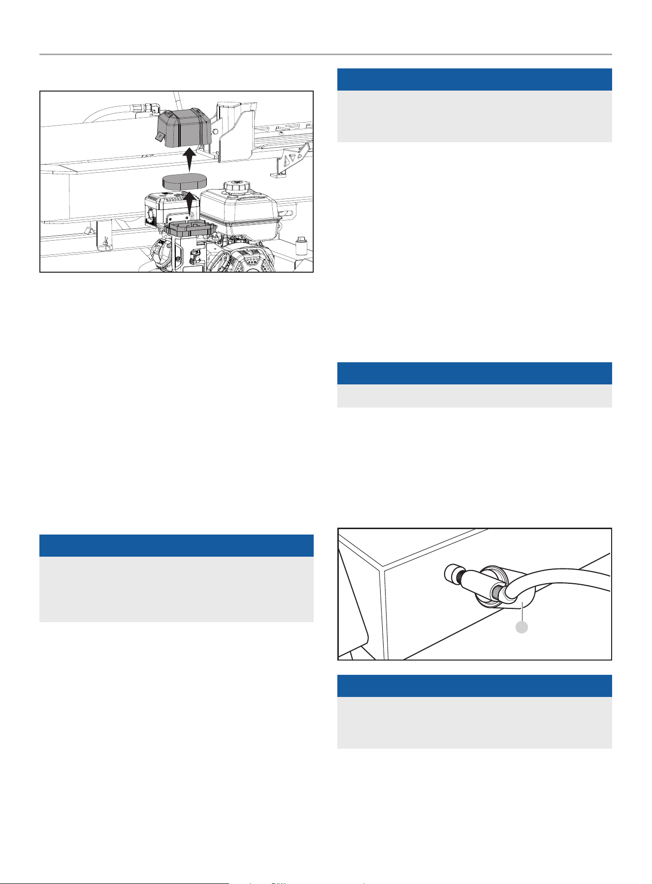
201519 - PARTIDOR DE TRONCOS DE 37 TONELADAS CON VIGA COMPLETA
MANTENIMIENTO
30
2. Remueva la tapa del filtro al igual que el elemento del filtro.
3. Lávelo con detergente líquido y agua. Estrújelo totalmente en
un paño limpio hasta secarlo.
4. Satúrelo con aceite de motor limpio.
5. Estrújelo en un paño absorbente limpio para eliminar el
exceso de aceite.
6. Coloque el filtro en el conjunto.
7. Vuelva a colocar la tapa del filtro de aire. Fije el lado mas
cercano al tanque y después gire hacia abajo para cerrar.
Asegure que la tapa del filtro de aire se brote a su lugar.
Cambiando el Aceite Hidráulico
Siempre apague el motor y desconecte la bujía.
Cambie el filtro del aceite hidráulico después de las primeras 50
horas de uso, luego cada 100 horas o cada temporada.
AVISO
Cuando los partidores de troncos no son utilizados por
periodos de tiempo extendidos, y son expuestos a condiciones
de cambio de temperatura, humedad a través de condensación
puede producirse dentro del tanque.
1. Inicie con el cilindro retraído y el interruptor de la valvula de
combustible de motor en la posición “APAGADO”.
2. Libere cualquier presión almacenada moviendo la palanca de
la válvula hacia delante y hacia atrás varias veces.
3. Coloque un recipiente debajo del tanque hidráulico.
Asegúrese que esté suficiente grande para contener el
contenido del tanque. Vea la sección de especificación del
modelo de este manual para las capacidades del tanque de
aceite hidráulico.
AVISO
El tapón de drenaje esta sellado con cinta Teflon
®
. Agregue
2-3 envolturas de cinta Teflon
®
como sea necesario cuando se
reemplace el tapón de drenaje para prevenir fuga de aceite.
4. Para drenar el aceite:
– Coloque un recipiente para aceite debajo del tapón de drenaje.
Desenrosque (izquierda) y remueva el tapón de drenaje por
debajo del tanque hidráulico. Permita que el aceite se drene
completamente del tanque al recipiente. Vuelva a aplicar cinta
selladora de Teflon
®
a la rosca de tapón de drenaje, luego
reinserte y gire (derecha) el tapón de drenaje. Apriete pero no
sobre apriete.
– Coloque un recipiente de drenaje de aceite debajo del filtro
de aceite externo. Desenrosque (izquierda) y remueva el
aceite hidráulico externo y drene cualquier aceite en el filtro al
recipiente. Una correa o llave para filtros de aceite puede ser
necesario.
AVISO
Aceite se derramará del filtro y de la caja del filtro.
– Localice un filtro de reemplazo aprobado.
– Lubrique el empaque del nuevo filtro con una capa
delgada de aceite limpio.
– Instale el nuevo filtro de aceite hidráulico. Enrosque
el nuevo filtro girando hacia la derecha (A). Apriete ¾
a 1 vuelta después que el empaque haga contacto.
A
AVISO
Instale un nuevo filtro de aceite hidráulico cada vez que el
aceite hidráulico se cambie (si su partidor de troncos viene con
esta característica.
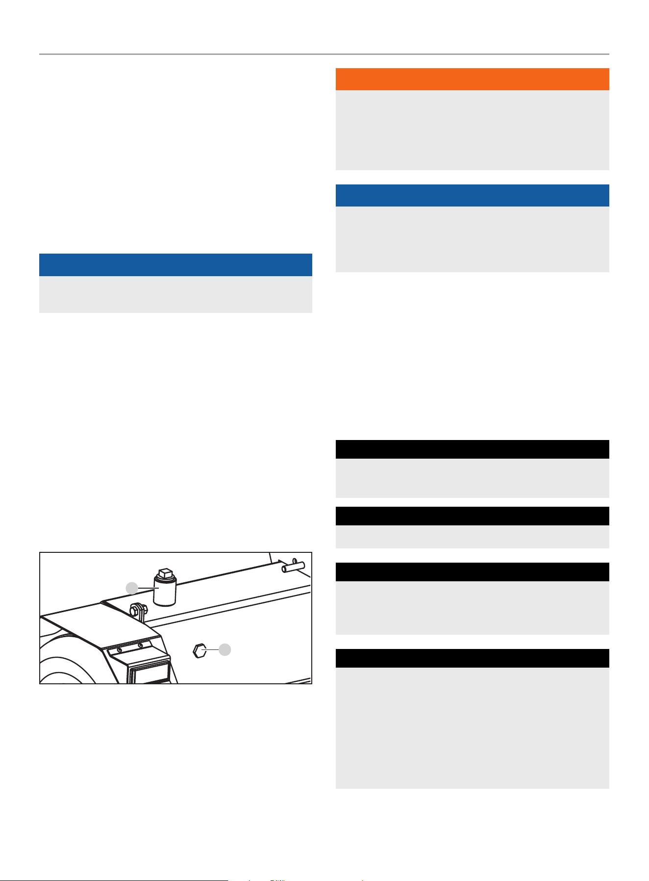
201519 - PARTIDOR DE TRONCOS DE 37 TONELADAS CON VIGA COMPLETA
MANTENIMIENTO
31
– Coloque un recipiente para aceite debajo de la manguera
grande y transparente que corre del tanque a la bomba.
– Afloje la abrazadera de la manguera sujetada a la
entrada en el tanque.
– Desconecte la manguera de la entrada y drene el
aceite en el recipiente.
– Usando una llave grande, desenrosque la entrada del
tanque para exponer el filtro interno del tanque.
– Inspeccione para cualquier escombro en la rejilla.
Usando un trapo limpio o pistola de aire, remueva
cualquier escombro con mucho cuidado.
AVISO
Tenga cuidado cuando maneje la rejilla ya que puede ser
dañada con facilidad.
– Aplique nueva cinta selladora de Teflon
®
a las
roscas, reinserte en el tanque y apriete. Tenga
cuidado al apretar, no apriete demasiado.
5. Desenrosque y retire el tapón de llenado del tanque en la
parte superior del tanque (B). Usando un embudo, agregue
aproximadamente 5 galones (18.9 L) de aceite hidráulico al
tanque. Limpie cualquier aceite derramado.
6. Gire la válvula de combustible a la posición “ENCENDIDO”, y
arranque el motor. Elimine el aire del sistema extendiendo y
retrayendo la cuña varias veces hasta que el movimiento sea
suave.
7. Verifique el nivel de aceite usando la mirilla. Agregue 1 gal.
(3.8 L) de aceite hidráulico, para que el nivel este visible en la
mirilla. (C)
b
C
8. Deshaga el aceite usado en una locación de reciclaje
aprobado en acuerdo con las regulaciones federales,
estatales, locales o provinciales.
ADVERTENCIA
Siempre apague el motor, desconecte la bujía y alivie la
presión del sistema antes de limpiar, ajustar o reparar el
partidor de troncos. Alivie la presión del sistema moviendo
la palanca de control del partidor varias veces de atrás para
adelante.
AVISO
Refiera a Especificaciones para una lista de filtros de repuesto
compatibles o llame a Champion Power Equipment al
1-877-338-0999 para ordenar un filtro OEM (original) de
repuesto.
Programa de Mantenimiento
Siga los intervalos de servicio indicados en el siguiente programa.
Dé servicio a su partidor de troncos más frecuentemente cuando
lo opere en condiciones adversas.
Comuníquese con nuestro Equipo de Apoyo Técnico al
1-877-338-0999 para ubicar al proveedor de servicio
más cercano certificado por CPE para sus necesidades de
mantenimiento para el partidor de troncos o el motor.
cAdA 8 HoRAS o diARiAMEnTE
Revise el nivel de aceite
Limpie alrededor de la entrada de aire y el silenciador
pRiMERAS 5 HoRAS
Cambie el aceite
cAdA 50 HoRAS o cAdA TEMpoRAdA
Limpie el filtro de aceite
Cambie el aceite si está operando bajo cargas pesadas o
en entornos calientes
cAdA 100 HoRAS o cAdA TEMpoRAdA
Cambie el aceite
Limpie/ajuste la bujía
Revise/ajuste el espacio de la válvula*
Limpie el parachispas
Limpie el tanque de combustible y el filtro*
Cambie el aceite hidráulico
Cambie el filtro del aceite hidráulico

201519 - PARTIDOR DE TRONCOS DE 37 TONELADAS CON VIGA COMPLETA
ALMACENAMIENTO
32
cAdA 250 HoRAS
Limpie la cámara de combustión*
cAdA AÑo
Inspeccione los rodamientos de las llantas y vuelva
a empacar la grasa de los rodamientos según sea
necesario.*
cAdA 3 AÑoS
Reemplace la línea de combustible*
* Debe ser desempeñado por propietarios con conocimiento y experiencia,
o bien un proveedor de servicio certificado por Champion Power Equipment.
ALMACENAMIENTO
Consulte la sección de Mantenimiento para las instrucciones de
limpieza adecuado.
Almacenamiento del Partidor de Troncos
1. El partidor de troncos debe enfriarse durante al menos
5 minutos antes de guardarlo.
2. Limpie el partidor de troncos antes de almacenarlo de
acuerdo con la sección de Mantenimiento.
3. Retracte la cuña para proteger la barra de la corrosión.
4. Limpie la viga y la cuña con un trapo untado en aceite para
prevenir el óxido y la corrosión.
El Motor Almacenado por Menos de 30 Días
1. Deje que el motor se enfríe completamente antes de
guardarlo.
2. Limpie el motor siguiendo las instrucciones de la sección de
Mantenimiento.
3. Para extender la vida de almacenamiento de combustible
agregue estabilizador de combustible .
4. Gire la válvula de combustible a la posición “APAGADO”.
El Motor Almacenado Durante más de
30 Días
1. Agregue un estabilizador dentro del tanque de combustible.
2. Drene completamente el combustible de la línea de
combustible y el carburador para que no se forme resina.
3. La válvula de combustible debe estar en la posición
“APAGADO”.
4. Deje que el motor funcione hasta que la falta de combustible
haya detenido el motor. Esto generalmente toma unos
minutos.
5. Deje que el motor se enfríe completamente antes de
almacenarlo.
6. Limpie el motor siguiendo las instrucciones de la sección
Mantenimiento.
7. Cambie el aceite.
8. Retire la bujía y vierta en el cilindro aproximadamente
½ oz (14.8 mL) de aceite. Arranque el motor lentamente para
distribuir el aceite y lubricar el cilindro.
9. Vuelva a colocar la bujía.
ADVERTENCIA
Nunca guarde el partidor de troncos junto a artefactos donde
haya una fuente de calor o llama expuesta, chispas o luces
piloto porque pueden encender los vapores de la gasolina.
NO guarde el partidor cerca de fertilizantes ni de ningún
material corrosivo. Los vapores de la gasolina pueden
encenderse incluso con el tanque de gasolina vacío.

201519 - PARTIDOR DE TRONCOS DE 37 TONELADAS CON VIGA COMPLETA
ESPECIfICACIONES
33
ESPECIfICACIONES
Especificaciones del Partidor de Troncos
Fuerza del ariete ..................................... 37 toneladas
Tiempo del ciclo ...................................... 16 segundos
Capacidad del tanque hidráulico .................... 5 gal (18.9 L)
Largo máx. del tronco............................... 24 in. (61 cm)
Peso máx. del tronco .............................. 100 lb. (45 kg)
Tamaño de la bola acopladora ....................... 2 in. (5.1 cm)
Tamaño de las llantas ............................ 16 in. (40.6 cm)
Velocidad máx. de remolque .................. 45 MPH (72 KM/H)
Tamaño del cilindro ...........5 in. × 23 in. (12.7 cm × 58.4 cm)
Tamaño de la varilla del cilindro ...................1.8 in. (4.5 cm)
Bomba de engranajes .....................................2-etapas
Presión máxima ...........................................3600 psi
Capacidad máxima del flujo ..................17 GPM (64.4 LPM)
Válvula de control ..................... Retén (retorno automático)
Peso neto ........................................ 560.1 lb. (254 kg)
Largo .......................................... 86.3 in. (219.2 cm)
Ancho ...........................................51.3 in. (130.2 cm)
Altura ...........................................41.7 in. (105.8 cm)
Especificaciones del Motor
Modelo ....................................................... R338P
Cilindrada .................................................... 338 cc
Tipo .................................................4-tiempos OHV
Tipo de arranque ........................................... Manual
Especificaciones del Aceite
NO SOBRELLENE.
Tipo ............................................Vea la gráfica abajo
Capacidad .....................................37.2 fl. oz (1100 ml)
-20 0 20 40 60
Temperatura de ambiente
Recomendación de Tipo de Aceite para Motor
80 100 120
-28.9
°F
°C -17.8 -6.7 4.4 15.6 26.7 37.8 48.9
10W-30
5W-30 Full Sintético Completo
10W-405W-30
AVISO
La temperatura va a afectar rendimiento del aceite del motor
y del motor. Cambie el tipo de aceite de motor usado basado
a la temperatura en la gráfica “Tipo de aceite de motor
recomendado”.
Sistema de Aceite Hidráulico
Capacidad .......................................... 6 gal. (22.7 L)
para su uso durante todo el año en los climas más cálidos.
(siempre por encima 32˚F / 0˚c):
– ISO 32/SAE10W
– Aceite Universal Hidráulico
para su uso durante todo el año en climas más fríos
(por debajo de 32˚F / 0˚c):
– Liquido de Transmisión Automática
Filtros de repuesto:
– Fram PH9342
– K&N HP-2008
– Wix 51361
Especificaciones de Combustible
Utilice gasolina normal sin plomo de 87 octanos como mínimo y un
contenido de etanol de menos de 10% en volumen. NO USE E15 o
E85. NO SOBRELLENE.
Capacidad de gasolina ............................ 1.45 gal. (5.5 L)
Especificaciones de la bujía
Tipo OEM (original de fabrica) .............................. F6RTC
Tipo de reemplazo ....................NGK BPR6ES o equivalente
Espacio ............................. 0.028-0.031 in. (0.7-0.8 mm)
Especificaciones de la Válvula
Espacio de admisión ............0.002-0.0039 in. (0.05-0.1 mm)
Espacio del escape ..............0.002-0.0039 in. (0.05-0.1 mm)
AVISO
Boletín técnico sobre el procedimiento de ajuste de la válvula
está en www.championpowerequipment.com

201519 - PARTIDOR DE TRONCOS DE 37 TONELADAS CON VIGA COMPLETA
ESPECIfICACIONES
34
Un Aviso Importante Sobre Temperatura
Su producto está diseñado y clasificado para un funcionamiento
continuo a temperaturas ambiente de hasta 104°F (40°C).
Cuando el producto se necesite, su producto puede ser operado a
temperaturas de 5°F (-15°C) a 122°F (50°C) por periodos breves.
Si el producto esta expuesto a temperaturas fuera de este rango
durante su almacenamiento, deberá colocarse dentro de este
rango nuevamente antes de su operación. En cualquier caso, el
producto siempre deberá operarse en exteriores, en un área bien
ventilada lejos de puertas, ventanas y otras aperturas.
AVISO
Cuando la temperatura esté por debajo de 32ºF (0ºC),
use líquido de transmisión automática (Dexron-III o similar).

201519 - PARTIDOR DE TRONCOS DE 37 TONELADAS CON VIGA COMPLETA
SOLUCIóN DE PRObLEMAS
35
SOLUCIóN DE PRObLEMAS
problema causa Solución
El motor no arranca.
Sin combustible. Agregue combustible.
Bujía defectuosa. Reemplace la bujía.
Unidad cargada durante el arranque. Retire la carga de la unidad.
El motor no arranca;
Arranca, pero funciona bruscamente.
Nivel de aceite bajo.
Llene el cigüeñal hasta el nivel correcto.
Coloque el partidor de troncos en una superficie
plana y nivelada.
Ahogador en posición incorrecta. Ajuste el ahogador.
Cable de la bujía suelto. Conecte el cable a la bujía.
El motor se apaga durante la operación.
Sin combustible. Llene el tanque.
Nivel de aceite bajo.
Llene el cigüeñal hasta el nivel correcto. Coloque
el partidor de troncos en una superficie plana y
nivelada.
El motor no puede proporcionar
suficiente energía o se sobrecalienta.
Ventilación insuficiente.
Revise si hay restricción de aire. Cámbielo a un
área bien ventilada.
El movimiento de la cuña es lento o
errático.
Aire en el sistema de aceite hidráulico.
Purgue el aire del sistema extendiendo y
retrayendo la cuña varias veces hasta que el
movimiento sea suave.
Escombros alojados en las guías de la
viga.
Quite los escombros de la viga.
Bajo nivel de aceite hidráulico.
Compruebe el nivel de aceite y agregue más según
sea necesario.
Escape de aceite del cilindro.
Sello defectuoso de la varilla del cilindro.
Póngase en contacto con el servicio de atención al
cliente.
Varilla de cilindro rayada o doblada.
Póngase en contacto con el servicio de atención al
cliente.
Conexión hidráulica floja. Ajuste la conexión hidráulica.
Sello defectuoso de la arandela de
combinación en la conexión hidráulica
del cilindro.
Póngase en contacto con el servicio de atención al
cliente.
La cuña no se extiende ni se retrae.
Válvula de control defectuosa.
Póngase en contacto con el servicio de atención al
cliente.
Bomba hidráulica defectuosa.
Póngase en contacto con el servicio de atención al
cliente.
Bajo nivel de aceite hidráulico.
Revise el nivel de aceite y añada según sea
necesario.
Rebote excesivo al remolcar. Llantas con presión baja.
Infle las llantas hasta la presión adecuada. Mire el
costado de la llanta.
para soporte técnico adicional:
Equipo de Apoyo Técnico
Sin costo: 1-877-338-0999
support@championpowerequipment.com

GARANTÍA*
CHAMPION POWER EQUIPMENT
GARANTÍA LIMITADA DE 2 AÑOS
Calificaciones de garantía
Para registrar su producto para la garantía y soporte técnico del
servicio de llamadas GRATIS de por vida, por favor visite:
https://www.championpowerequipment.com/register
Para completar la registración, necesitará incluir una copia del
recibo de compra como prueba de compra original. La prueba
de compra es requerida para servicio de garantía. Por favor
regístrese dentro de diez (10) días de la fecha de compra.
Garantía de reparación/reemplazo
CPE garantiza al comprador original que los componentes
mecánicos y eléctricos estarán libres de defectos en materiales
y mano de obra por un período de dos años (partes y mano de
obra) de la fecha original de compra y 180 días (partes y mano de
obra) para uso comercial y industrial. Los gastos de transporte del
producto sometido a reparación o reemplazo bajo esta garantía
son de exclusiva responsabilidad del comprador. Esta garantía
sólo se aplica al comprador original y no es transferible.
No devuelva la unidad al local de compra
Comuníquese con el servicio técnico de CPE, el cual diagnosticará
todo problema por teléfono o correo electrónico. Si el problema
no se corrige mediante este método, CPE, a su criterio, autorizará
la evaluación, reparación o reemplazo de la parte o componente
defectuoso en un centro de servicio de CPE. CPE le proporcionará
un número de caso para obtener servicio de garantía. Consérvelo
como referencia futura. Esta garantía no cubrirá las reparaciones
o reemplazos no autorizados ni efectuados en un taller no
autorizado.
Exclusiones de la garantía
Esta garantía no cubre las reparaciones y equipos siguientes:
Desgaste normal
Productos con componentes mecánicos y eléctricos necesitan
partes y servicio periódico para el buen desempeño. Esta garantía
no cubre la reparación cuando el uso normal haya agotado la vida
útil de una parte o del equipo en su totalidad.
Instalación, uso y mantenimiento
Esta garantía no aplicará a partes y/o mano de obra si el
producto se ha considerado haber sido mal usado, descuidado,
involucrado en un accidente, abusado, cargado más allá de los
limites del producto, modificado, inapropiadamente instalado o
conectado incorrectamente a cualquier componente eléctrico. El
mantenimiento normal no esta cubierto por esta garantía y no es
requerido de que sea desempeñado en una instalación de servicio
o por una persona autorizada por CPE.
Otras exclusiones
Esta garantía excluye:
– Defectos cosméticos tales como pintura, calcomanías, etc.
– Artículos de desgaste tales como elementos filtrantes, juntas
tóricas, etc.
– Partes accesorias tales como mangueras, cubiertas de
almacenamiento, etc.
– Fallas debido a desastres naturales y otros sucesos de fuerza
mayor que escapan al control del fabricante.
– Problemas causados por partes que no sean repuestos
originales de Champion Power Equipment.
Límites de la garantía implícita y daños
consecuentes
Champion Power Equipment rechaza toda obligación de cubrir
toda pérdida de tiempo, del uso de este producto, flete, o
cualquier reclamo incidental o consecuente por parte de cualquier
usuario de este producto. ESTA GARANTÍA Y LAS GARANTÍAS
ADJUNTAS DE CONTROL DE EMISIONES U.S. EPA y/o CARB
(CUANDO APLICABLES) REEMPLAZAN A TODAS LAS DEMÁS
GARANTÍAS, YA SEAN EXPRESAS O IMPLÍCITAS, INCLUYENDO
GARANTÍAS DE COMERCIABILIDAD O CAPACIDAD PARA UN
PROPOSITO PARTICULAR.
La unidad proporcionada en intercambio quedará sujeta a la
garantía de la unidad original. La vigencia de la garantía para la
unidad de intercambio se seguirá calculando según la fecha de
compra de la unidad original.
Esta garantía le da ciertos derechos legales que pueden cambiar
de estado a estado o provincia a provincia. Su estado o provincia
puede también tener otros derechos a los cuales usted tenga
derecho que no están enlistados en esta garantía.
Información de contacto
Dirección
Champion Power Equipment, Inc.
6370 S Pioneer Way, Unit 101
Las Vegas, NV 89113 EE.UU.
www.championpowerequipment.com
Servicio al cliente
Sin Costo: 1-877-338-0999
info@championpowerequipment.com
No. Fax: 1-562-236-9429
Servicio técnico
Sin Costo: 1-877-338-0999
tech@championpowerequipment.com
*Excepto como de otra manera estipulado en cualquier de las siguientes garantías del sistema de control de emisiones (cuando aplicables) adjuntas para el Sistema de Control de Emisiones:
Agencia de la Protección Ambiental de EE.UU. (EPA) y/o Consejo de Recursos del Aire de California (CARB).

GARANTÍA DEL SISTEMA DE CONTROL DE EMISIONES
DE CHAMPION POWER EQUIPMENT, INC. (CPE) Y DE LA AGENCIA DE PROTECCIÓN
MEDIOAMBIENTAL DE LOS ESTADOS UNIDOS (EPA DE EE.UU.)
Su motor de Champion Power Equipment (CPE) cumple con regulaciones sobre emisiones de EPA de EE.UU.
SUS DERECHOS Y OBLIGACIONES DE GARANTÍA:
La US EPA y CPE se complacen en explicarles la Garantía de los Sistemas de Control de Emisiones Federal en su equipo pequeño de motor
para uso fuera de carretera (SORE) y equipo motorizado del 2024. Motores nuevos y equipo deben ser diseñados, fabricados y equipados,
en el tiempo su venta, para cumplir con las normas del U.S. EPA para motores pequeños de uso fuera de carretera (SORE).
CPE garantiza el sistema de control de emisiones en su pequeño motor para uso fuera de carretera (SORE) y el equipo durante el período
de tiempo que se indica a continuación, siempre que no se haya cometido abuso, negligencia, o mantenimiento inadecuado de su el
equipo.
Su sistema de control de emisiones puede incluir piezas como: carburador, sistema de inyección de combustible, el sistema de ignición,
convertidor catalítico, y líneas de combustible. Además, se puede incluir mangueras, bandas, conectores y otros ensamblajes relacionados
con las emisiones. Cuando se produzca un problema cubierto por la garantía, CPE reparará su pequeño motor para uso fuera de carretera
(SORE) sin costo para usted, incluyendo el diagnóstico, las piezas y la mano de obra.
COBERTURA DE LA GARANTÍA DEL FABRICANTE:
Este sistema de control de emisiones tiene una garantía de dos años, sujeto a provisiones establecidos en la parte de abajo. Si durante el
periodo de garantía alguna pieza relacionada con emisiones en su pequeño motor es defectuosa, será reparada o reemplazada por CPE.
RESPONSABILIDADES DEL PROPIETARIO DE LA GARANTÍA:
Como propietario del motor pequeño para uso fuera de carretera (SORE), es responsable de realizar el mantenimiento necesario indicado
en su Manual del propietario. CPE recomienda conservar todos sus recibos por trabajos de mantenimiento de su pequeño motor para uso
fuera de carretera (SORE), pero CPE no puede negar la cobertura de la garantía únicamente por no presentar los recibos o por su falla de
asegurar el desempeño de todo el mantenimiento programado.
Como propietario del motor pequeño para uso fuera de carretera (SORE), debe tener en cuenta que CPE puede negar la cobertura de la
garantía si su motor pequeño para uso fuera de carretera (SORE) o una pieza se ha averiado debido a abuso, negligencia, mantenimiento
inadecuado o modificaciones no autorizadas.
Usted es responsable de llevar su motor pequeño para uso fuera de la carretera (SORE) a un centro de servicio o un centro de servicio
alternativo autorizado de CPE como se describe en (3)(f) a continuación o al distribuidor de CPE o a CPE, Las Vegas, NV. desde que surja el
problema. Las reparaciones en garantía se realizarán en un tiempo razonable, no excediendo los 30 días.
Si tiene alguna cuestión sobre la cobertura de su garantía, contacte con:
Champion Power Equipment, Inc.
Servicio al Cliente
6370 S Pioneer Way, Unit 101
Las Vegas, NV 89113
1-877-338-0999
tech@championpowerequipment.com

GARANTÍA DEL SISTEMA DE EMISIÓNES
A continuación, se presentan las cláusulas específicas relacionadas con la cobertura de la garantía del sistema de control de
emisiones (ECS).
1. APLICABILIDAD: Esta garantía se aplica a modelos de motor pequeño para uso fuera de carretera (SORE) del año 1997 y posteriores.
El período de garantía de ECS comienza en la fecha de entrega al comprador final del nuevo motor o equipo, y se extiende por 24
meses consecutivos a partir de tal fecha.
2. COBERTURA DE LA GARANTÍA GENERAL DE EMISIONES
CPE garantiza al comprador final del nuevo motor o equipo y a los compradores posteriores, que cada uno de sus pequeños motores
para uso fuera de carretera (SORE):
2a. Ha sido diseñado, fabricado y equipado para que cumpla con los estándares de emisiones de la EPA de EE. UU. para motores de
encendido por chispa de 19 kilovatios o menos.
2b. Está libre de defectos en los materiales y mano de obra que provoquen averías en piezas garantizadas idénticas en todos los
aspectos materiales a la pieza descrita en la solicitud de certificación del fabricante del motor por un período de dos años.
3. LA GARANTÍA SOBRE LAS PIEZAS RELACIONADAS CON LAS EMISIONES SE INTERPRETARÁN DE LA SIGUIENTE MANERA:
3a. Cualquier pieza en garantía que no tenga programado su reemplazo como parte del mantenimiento requerido en el Manual del
propietario, deberá estar garantizada durante el Período de Garantía de ECS. Si alguna de estas piezas se avería durante el
Período de Garantía de ECS, debe ser reparada y reemplazada por CPE de acuerdo con la subsección “d” siguiente. Cualquier
pieza reparada o reemplazada bajo la Garantía de ECS estará garantizada por cualquier restante Período de Garantía de ECS.
3b. Cualquier pieza en garantía relacionada con las emisiones que tenga programado su reemplazo solo para una inspección regular
según se especifica en el Manual del Propietario, deberá estar en garantía por el Período de Garantía de ECS. Una declaración en
dichas instrucciones escritas a efectos de “reparar o reemplazar según sea necesario”, no reducirá el Período de Garantía de ECS.
Cualquier pieza reparada o reemplazada bajo la Garantía de ECS estará garantizada por el restante Período de Garantía de ECS.
3c. Cualquier pieza en garantía relacionada con las emisiones que tenga programado su reemplazo según el mantenimiento requerido
en el Manual del propietario, deberá estar en garantía durante el período de tiempo anterior al primer reemplazo programado
de esa pieza. Si la pieza se avería antes del primer recambio programado, CPE la reparará o reemplazará de acuerdo con la
subsección “d” siguiente. Cualquier pieza relacionada con las emisiones, reparada o reemplazada bajo la Garantía de ECS, deberá
estar en garantía por el restante Período de Garantía de ECS antes del primer reemplazo programado para tal pieza relacionada
con las emisiones.
3d. La reparación o reemplazo de cualquier pieza en garantía relacionada con las emisiones según esta Garantía de ECS se realizará
en un Centro de Servicio Autorizado de CPE sin cargo para el propietario.
3e. El propietario no deberá abonar ningún cargo por el trabajo de diagnóstico que determine que una pieza cubierta por la Garantía
de ECS es defectuosa, siempre que dicho diagnóstico se realice en un Punto de Servicio Autorizado de CPE.
3f. CPE se hará cargo de las reparaciones cubiertas por la garantía de emisiones de escape y evaporación en los centros de servicio
no autorizados en las siguientes circunstancias:
i. El servicio es requerido en un centro poblacional con una población de más de 100,000 habitantes según el Censo de 2000 de
EE. UU., que no tenga un Centro de Servicio Autorizado de CPE Y
ii. El servicio es requerido a más de 100 millas de un centro de servicio autorizado de CPE. El límite de 100 millas no se aplica en
los siguientes estados: Alaska, Arizona, Colorado, Hawaii, Idaho, Montana, Nebraska, Nevada, Nuevo México, Oregón, Texas,
Utah y Wyoming.
3g. CPE será responsable de los daños a otros componentes originales del motor o de las modificaciones aprobadas provocadas por
el fallo de una pieza relacionada con las emisiones que esté cubierta por la Garantía de ECS.
3h. Durante el período de garantía de ECS, el CPE debe mantener un suministro suficiente de piezas relacionadas con las emisiones
que estén en garantía para satisfacer la demanda esperada de estas piezas relacionadas con las emisiones.
3i. Cualquier pieza de repuesto relacionada con las emisiones autorizada y aprobada por CPE puede ser utilizada en el desempeño
de cualquier mantenimiento o reparación de garantía de ECS y se suministrará sin cargo al propietario. Tal uso no reduce la
obligación de garantía de CPE.
3j. Las partes adicionales o modificadas no aprobadas no se pueden utilizar para modificar o reparar un motor de CPE. Dicho
uso anula esta Garantía de ECS y supondrá motivo suficiente para rechazar una reclamación de Garantía de ECS. CPE no será
responsable según este documento por las averías de cualquier pieza en garantía de un motor de CPE provocada por el uso de
dicha pieza adicional o modificada no aprobada.

LAS PIEZAS RELACIONADAS CON LAS EMISIONES INCLUYEN LAS SIGUIENTES: (SEGÚN LAS PARTES DE
LA LISTA APLICABLES AL MOTOR)
Sistemas cubiertos por esta
garantía
Descripción de piezas
Sistema de medición de
combustible
Regulador de combustible, Carburador y piezas internas
Sistema de inducción de aire Filtro de aire, Colector de admisión.
Sistema de encendido Bujías y partes, Sistema de encendido por magneto.
Sistema del escape Colector del escape, Convertidor catalítico
Partes misceláneas Tubería, Acopladores, Sellos, Empaques, y Abrazaderas asociados con estos sistemas enlistados.
Controles de evaporación Depósito de combustible, Tapón de combustible, Tubos de combustible (para combustible líquido y
vapores de combustible), Conexiones de tubos de combustible, Abrazaderas, Válvulas de alivio de
presión, Válvulas de control, Solenoides de control, Controles electrónicos, Diafragmas de control
de vacío, Cables de control, Conexiones de control, Válvulas de purga, Juntas, Separador de líquido/
vapor, Filtro de carbono, Soportes de montaje del filtro, Conector del puerto de purga del carburador
PARA OBTENER EL SERVICIO DE GARANTÍA:
Debe llevar su motor de CPE o el producto en el que está instalado, junto con su tarjeta de registro de garantía u otra prueba de la fecha
de compra original a su cargo, a cualquier distribuidor de Champion Power Equipment autorizado por Champion Power Equipment, Inc.
para vender y prestar servicio a tal producto de CPE durante su horario de trabajo. Las localizaciones alternativas de servicio definidas en
la Sección (3)(f) anterior, deben ser aprobadas por CPE antes del servicio. No se denegarán las reclamaciones por reparaciones o ajustes
provocados únicamente por defectos en el material o mano de obra provocados por el mantenimiento o uso incorrecto del motor.
Si tiene alguna cuestión sobre sus derechos y responsabilidades de garantía, o para obtener servicio de garantía, comuníquese
con el Servicio al Cliente de Champion Power Equipment, Inc.
Champion Power Equipment, Inc.
Servicio de Atención al Cliente
6370 S Pioneer Way, Unit 101
Las Vegas, NV 89113
1-877-338-0999
tech@championpowerequipment.com
