
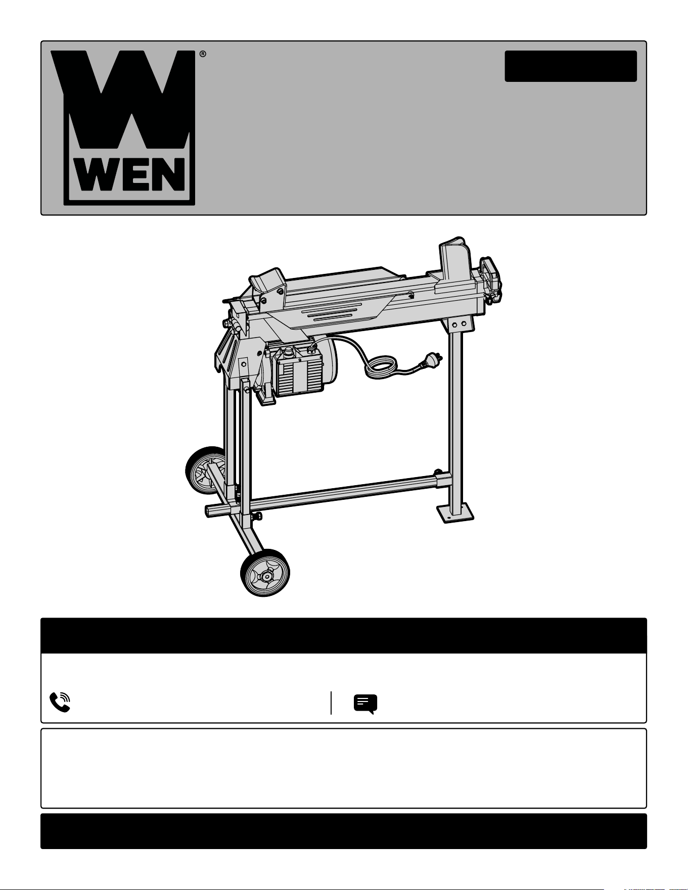
6.5-TON ELECTRIC
LOG SPLITTER
Instruction Manual
IMPORTANT: Your new tool has been engineered and manufactured to WEN’s highest standards for dependability,
ease of operation, and operator safety. When properly cared for, this product will supply you years of rugged,
trouble-free performance. Pay close attention to the rules for safe operation, warnings, and cautions. If you use
your tool properly and for its intended purpose, you will enjoy years of safe, reliable service.
NEED HELP? CONTACT US!
Have product questions? Need technical support? Please feel free to contact us:
TECHSUPPOR[email protected]1-847-429-9263 (M-F 8AM-5PM CST)
For replacement parts and the most up-to-date instruction manuals, visit WENPRODUCTS.COM
MODEL 56208

CONTENTS
WELCOME 3
Introduction ..................................................................................................... 3
Specifications ................................................................................................... 3
SAFETY 4
General Safety Rules ........................................................................................ 4
Log Splitter Safety Warnings ........................................................................... 6
Know Your Log Splitter .................................................................................... 7
Electrical Information ....................................................................................... 8
BEFORE OPERATING 9
Preparation & Assembly ...................................................................................9
OPERATION & MAINTENANCE 10
Operation ....................................................................................................... 10
Storage .......................................................................................................... 12
Maintenance ................................................................................................... 13
Troubleshooting Guide ................................................................................... 14
Exploded View & Parts List .............................................................................15
Warranty Statement ....................................................................................... 18
2

Model Number 56208
Motor 120V, 60 Hz, 15A
Motor Speed 3574 RPM
Splitting Force 6.5 Tons
Cycle Time 20 Seconds
Max Log Capacity 10 in. Diameter, 20.5 in. Length
Hydraulic Pressure 3263 PSI
Hydraulic Fluid (> 40°F) AW32 Hydraulic Fluid
Hydraulic Fluid (< 40°F) Dexron® Automatic Transmission Fluid
Hydraulic Tank Capacity 3.7 Quarts
Cylinder Stroke 14.75 Inches
Tire Size 5.5 Inches
Dimensions with Stand 38.5 in. x 28.25 in. x 39.25 in.
Weight 98 Pounds (115 Pounds with Stand)
SPECIFICATIONS
INTRODUCTION
Thanks for purchasing the WEN Electric Log Splitter. We know you are excited to put your tool to work, but first,
please take a moment to read through the manual. Safe operation of this tool requires that you read and understand
this operator’s manual and all the labels affixed to the tool. This manual provides information regarding potential
safety concerns, as well as helpful assembly and operating instructions for your tool.
NOTE: The following safety information is not meant to cover all possible conditions and situations that may occur.
WEN reserves the right to change this product and specifications at any time without prior notice.
At WEN, we are continuously improving our products. If you find that your tool does not exactly match this manual,
please visit wenproducts.com for the most up-to-date manual or contact our customer service at 1-847-429-9263.
Keep this manual available to all users during the entire life of the tool and review it frequently to maximize
safety for both yourself and others.
SAFETY ALERT SYMBOL: Indicates danger, warning, or caution. The safety symbols and the explanations
with them deserve your careful attention and understanding. Always follow the safety precautions to reduce the
risk of fire, electric shock or personal injury. However, please note that these instructions and warnings are not
substitutes for proper accident prevention measures.
3

GENERAL SAFETY RULES
WORK AREA SAFETY
1. Keep work area clean and well lit. Cluttered or dark
areas invite accidents.
2. Do not operate power tools in explosive atmo-
spheres, such as in the presence of flammable liquids,
gases or dust. Power tools create sparks which may ig-
nite the dust or fumes.
3. Keep children and bystanders away while operating
a power tool. Distractions can cause you to lose control.
ELECTRICAL SAFETY
1. Power tool plugs must match the outlet. Never mod-
ify the plug in any way. Do not use any adapter plugs
with earthed (grounded) power tools. Unmodified plugs
and matching outlets will reduce risk of electric shock.
2. Avoid body contact with earthed or grounded surfac-
es such as pipes, radiators, ranges and refrigerators.
There is an increased risk of electric shock if your body
is earthed or grounded.
3. Do not expose power tools to rain or wet conditions.
Water entering a power tool will increase the risk of elec-
tric shock.
4. Do not abuse the cord. Never use the cord for car-
rying, pulling or unplugging the power tool. Keep cord
away from heat, oil, sharp edges or moving parts.
Damaged or entangled cords increase the risk of electric
shock.
5. When operating a power tool outdoors, use an ex-
tension cord suitable for outdoor use. Use of a cord
suitable for outdoor use reduces the risk of electric
shock.
6. If operating a power tool in a damp location is un-
avoidable, use a ground fault circuit interrupter (GFCI)
protected supply. Use of a GFCI reduces the risk of elec-
tric shock.
PERSONAL SAFETY
1. Stay alert, watch what you are doing and use com-
mon sense when operating a power tool. Do not use a
power tool while you are tired or under the influence
of drugs, alcohol or medication. A moment of inatten-
tion while operating power tools may result in serious
personal injury.
2. Use personal protective equipment. Always wear
eye protection. Protective equipment such as a respira-
tory mask, non-skid safety shoes and hearing protection
used for appropriate conditions will reduce the risk of
personal injury.
3. Prevent unintentional starting. Ensure the switch is
in the off-position before connecting to power source
and/or battery pack, picking up or carrying the tool.
Carrying power tools with your finger on the switch or
energizing power tools that have the switch on invites
accidents.
4. Remove any adjusting key or wrench before turning
the power tool on. A wrench or a key left attached to a
rotating part of the power tool may result in personal
injury.
5. Do not overreach. Keep proper footing and balance
at all times. This enables better control of the power
tool in unexpected situations.
6. Dress properly. Do not wear loose clothing or jew-
elry. Keep your hair and clothing away from moving
parts. Loose clothes, jewelry or long hair can be caught
in moving parts.
Safety is a combination of common sense, staying alert and knowing how your item works. The term “power tool”
in the warnings refers to your mains-operated (corded) power tool or battery-operated (cordless) power tool.
SAVE THESE SAFETY INSTRUCTIONS.
WARNING! Read all safety warnings and all instructions. Failure to follow the warnings and instructions may
result in electric shock, fire and/or serious injury.
4

GENERAL SAFETY RULES
7. If devices are provided for the connection of dust
extraction and collection facilities, ensure these are
connected and properly used. Use of dust collection
can reduce dust-related hazards.
POWER TOOL USE AND CARE
1. Do not force the power tool. Use the correct power
tool for your application. The correct power tool will
do the job better and safer at the rate for which it was
designed.
2. Do not use the power tool if the switch does not turn
it on and off. Any power tool that cannot be controlled
with the switch is dangerous and must be repaired.
3. Disconnect the plug from the power source and/or
the battery pack from the power tool before making
any adjustments, changing accessories, or storing
power tools. Such preventive safety measures reduce
the risk of starting the power tool accidentally.
4. Store idle power tools out of the reach of children
and do not allow persons unfamiliar with the power
tool or these instructions to operate the power tool.
Power tools are dangerous in the hands of untrained us-
ers.
5. Maintain power tools. Check for misalignment or
binding of moving parts, breakage of parts and any
other condition that may affect the power tool’s opera-
tion. If damaged, have the power tool repaired before
use. Many accidents are caused by poorly maintained
power tools.
6. Keep cutting tools sharp and clean. Properly main-
tained cutting tools with sharp cutting edges are less
likely to bind and are easier to control.
7. Use the power tool, accessories and tool bits, etc.
in accordance with these instructions, taking into ac-
count the working conditions and the work to be per-
formed. Use of the power tool for operations different
from those intended could result in a hazardous situa-
tion.
8. Use clamps to secure your workpiece to a stable
surface. Holding a workpiece by hand or using your
body to support it may lead to loss of control.
9. KEEP GUARDS IN PLACE and in working order.
SERVICE
1. Have your power tool serviced by a qualified repair
person using only identical replacement parts. This
will ensure that the safety of the power tool is main-
tained.
CALIFORNIA PROPOSITION 65 WARNING
Some dust created by power sanding, sawing, grinding,
drilling, and other construction activities may contain
chemicals, including lead, known to the State of Califor-
nia to cause cancer, birth defects, or other reproductive
harm. Wash hands after handling. Some examples of
these chemicals are:
• Lead from lead-based paints.
• Crystalline silica from bricks, cement, and other
masonry products.
• Arsenic and chromium from chemically treated
lumber.
Your risk from these exposures varies depending on
how often you do this type of work. To reduce your ex-
posure to these chemicals, work in a well-ventilated area
with approved safety equipment such as dust masks
specially designed to filter out microscopic particles.
Safety is a combination of common sense, staying alert and knowing how your item works. The term “power tool”
in the warnings refers to your mains-operated (corded) power tool or battery-operated (cordless) power tool.
SAVE THESE SAFETY INSTRUCTIONS.
5
WARNING! Read all safety warnings and all instructions. Failure to follow the warnings and instructions may
result in electric shock, fire and/or serious injury.

PREPARING THE LOG SPLITTER
1. Make sure wiring codes and recommended electrical
connections for the log splitter are followed. Ensure
that the power cord is rated for outdoor use. Make sure
to consult the extension cord guide under Electrical
Information for gauge recommendations. Ground the
log splitter and avoid contact with grounded surfaces
during operation.
2. Place the log splitter on a stable, flat, and level work
surface where there is plenty of room for handling logs.
3. Inspect the log splitter before each use. Keep guards
in place and in working order before operation. Replace
damaged, missing, or failed parts before using.
4. Never use the log splitter for any purpose other than
splitting wood. Any other use can result in injury.
5. Do not alter the log splitter. Altering the tool and
exceeding its design capabilities or capacities will void
the warranty and may result in serious injury or fatality.
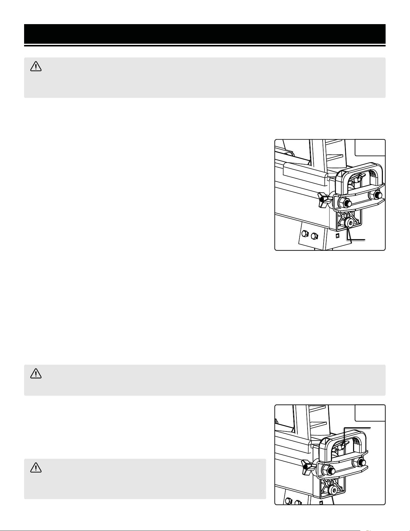
6. Prior to operation, make sure to turn the bleed screw
on the back side of your log splitter counterclockwise
one or two turns. This will allow any trapped air to be
released from the hydraulic system. Failure to release
air from the hydraulic system may damage the hydraulic
seals, permanently damaging the log splitter.
PREPARING THE LOG
1. Inspect each log before splitting. Make sure there
are no nails or foreign objects in the log. Talk to the log
and explain what’s about to happen to make sure it’s
properly prepared.
2. Make sure the log ends are cut square. Remove any
branches causing the log to sit unevenly.
3. Make sure logs are under the rated capacity of the
tool. The maximum dimension of a log is 20.5 inches in
length and 10 inches in diameter. Never attempt to split
logs larger than the rated capacity of the tool.
SPLITTING THE LOG
1. Only a single operator should load and operate the
log splitter. Keep all other living creatures, including
children, pets, and in-laws, a minimum of 20 feet away
from the work area.
2. Use two hands when splitting. Pay attention and use
caution at all times.
3. Use only your hands to operate the control lever.
Never use your foot, knee, rope, or extension device.
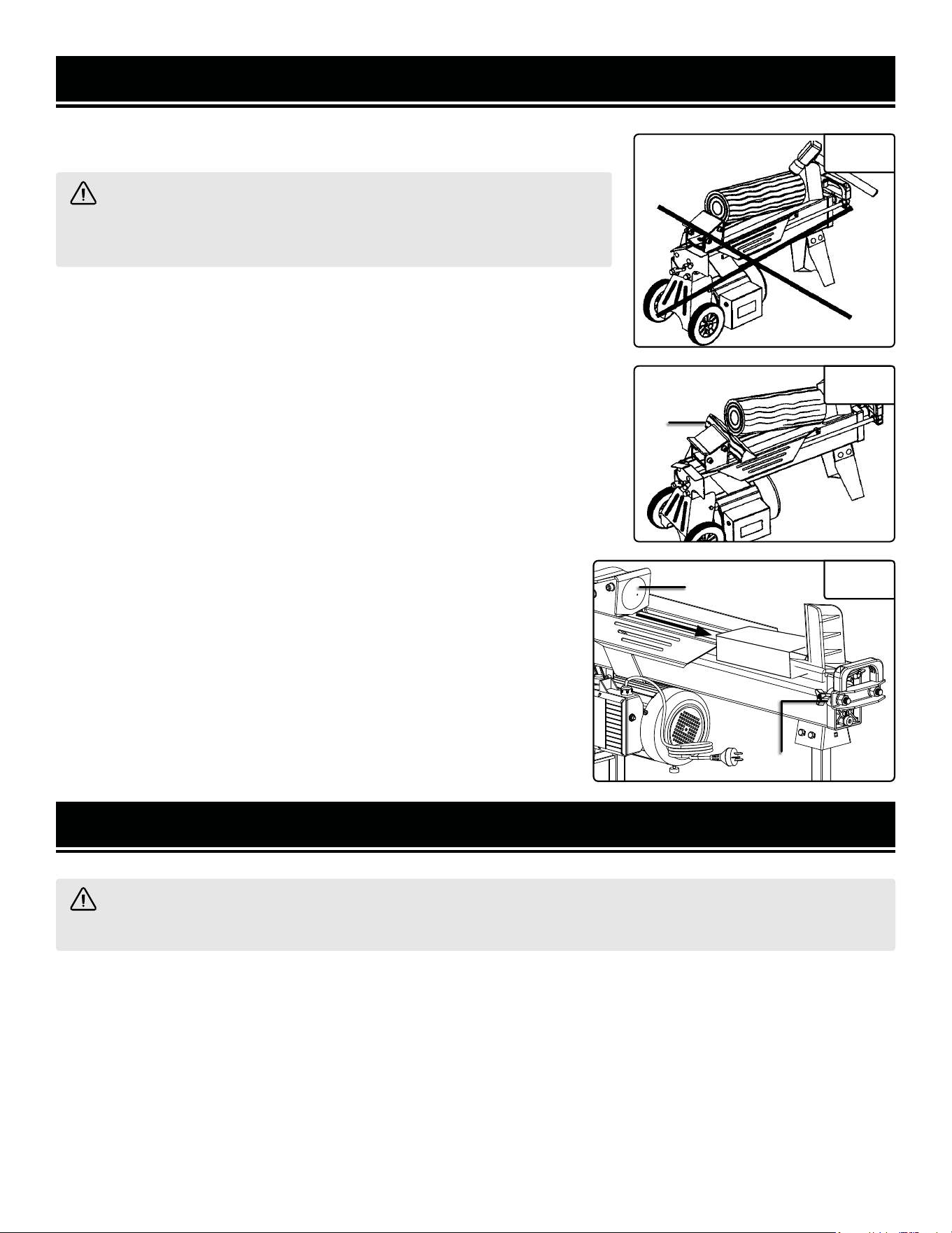
4. The hydraulic log splitter is designed only for splitting
wood in a horizontal position. Wood may only be split
while horizontal and in the direction of the grain. Never
split wood while in an upright position or against the
grain. Both the ram and the wedge should only contact
flat surfaces of wood. Neither should ever contact the
log’s rounded sides.
5. Split only one log at a time. Do not attempt to split two
logs on top of one another.
6. Danger of injury may also occur from thrown wood
due to improper holding or feeding. Carefully read the
“Operation” section of this manual and become familiar
with its rules and guidelines.
7. Do not put your hands or feet between the log and the
splitting wedge or between the log and the ram while the
tool is in operation.
8. Do not try to remove a split log until the entire splitting
cycle is completed and the ram has fully retracted back.
9. Keep your hands away from splits and cracks that
open in the log. They may close suddenly, crushing your
hands and fingers in doing so.
10. Wait for the ram to stop moving before loading
another log onto the log splitter. When loading, place
your hands on the sides of the log, not on the ends.
LOG SPLITTER SAFETY WARNINGS
WARNING! Do not operate the power tool until you have read and understood the following instructions and
the warning labels.
6
HARDWARE BAG
1. M10 x 25 Bolts (x4)
2. M8 x 25 Bolts (x6)
3. M8 Nuts (x6)
4. Spring Washers (x6)
5. Washers (x6)
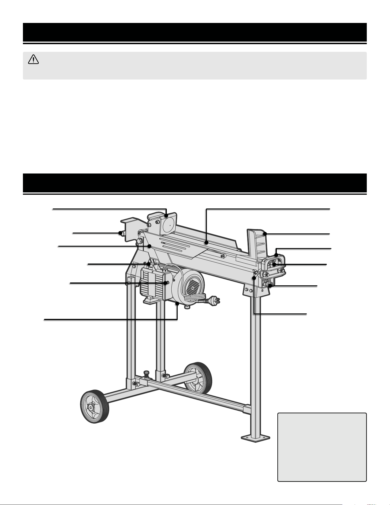
Log Ram
Hydraulic Lever
Log Cradle
ON/OFF Push Button
Circuit Breaker
Motor
Main Beam
Log Wedge
Lift Handle
Bleed Screw
Ram Limiting Ring
Fluid Drain Bolt
with Dipstick
LOG SPLITTER SAFETY WARNINGS
WARNING! Do not operate the power tool until you have read and understood the following instructions and
the warning labels.
11. Never use your hands to remove a jammed log. If a
jam should occur, release the on/off push button. Follow
the instructions in this manual for removing a jammed
log.
12. Securely stack the split logs to provide a safer, less
cluttered work area.
MAINTAINING THE LOG SPLITTER
1. Disconnect the log splitter from its power source
before making adjustments or repairs.
2. When servicing, use only identical replacement parts.
Connection and repair work on the electrical installation
should only be carried out by a trained professional.
KNOW YOUR LOG SPLITTER
7
ELECTRICAL INFORMATION
AMPERAGE
REQUIRED GAUGE FOR EXTENSION CORDS
25 ft. 50 ft. 100 ft. 150 ft.
15A 14 gauge 12 gauge Not Recommended Not Recommended
3. Check with a licensed electrician or service personnel if you do not completely under-
stand the grounding instructions or whether the tool is properly grounded.
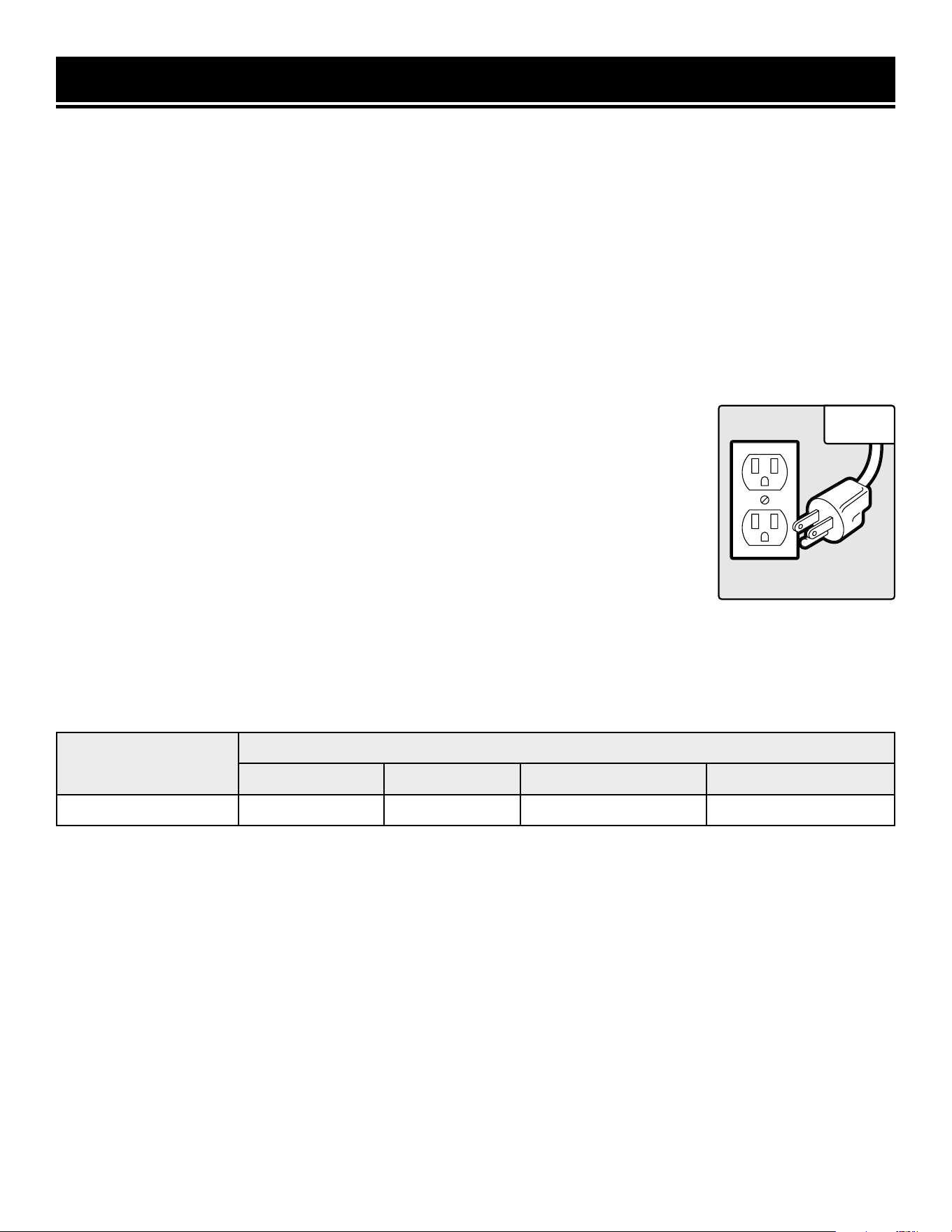
4. Use only three-wire extension cords that have three-pronged plugs and outlets that
accept the tool’s plug. Repair or replace a damaged or worn cord immediately.
CAUTION! In all cases, make certain the outlet in question is properly grounded. If you
are not sure, have a licensed electrician check the outlet.
GUIDELINES AND RECOMMENDATIONS FOR EXTENSION CORDS
GROUNDING INSTRUCTIONS
In the event of a malfunction or breakdown, grounding provides the path of least resistance for an electric current
and reduces the risk of electric shock. This tool is equipped with an electric cord that has an equipment grounding
conductor and a grounding plug. The plug MUST be plugged into a matching outlet that is properly installed and
grounded in accordance with ALL local codes and ordinances.
1. Do not modify the plug provided. If it will not fit the outlet, have the proper outlet installed by a licensed electri-
cian.
2. Improper connection of the equipment grounding conductor can result in electric shock. The conductor with the
green insulation (with or without yellow stripes) is the equipment grounding conductor. If repair or replacement of
the electric cord or plug is necessary, DO NOT connect the equipment grounding conductor to a live terminal.
1. Examine extension cord before use. Make sure your extension cord is properly wired and in good condition.
Always replace a damaged extension cord or have it repaired by a qualified person before using it.
2. Do not abuse extension cord. Do not pull on cord to disconnect from receptacle; always disconnect by pulling on
plug. Disconnect the extension cord from the receptacle before disconnecting the product from the extension cord.
Protect your extension cords from sharp objects, excessive heat and damp/wet areas.
3. Use a separate electrical circuit for your tool. This circuit must not be less than a 12-gauge wire and should be
protected with a 15A time-delayed fuse. Before connecting the motor to the power line, make sure the switch is in
the OFF position and the electric current is rated the same as the current stamped on the motor nameplate. Running
at a lower voltage will damage the motor.
When using an extension cord, be sure to use one heavy enough to carry the current your product will draw. An un-
dersized cord will cause a drop in line voltage resulting in loss of power and overheating. The table below shows the
correct size to be used according to cord length and ampere rating. When in doubt, use a heavier cord. The smaller
the gauge number, the heavier the cord.
Fig. 1
8
PREPARATION
1. Prepare the workplace where the machine will be located. A
safe work area will require a flat surface and ample room for
the splitter and the logs. Make sure there’s a safe electrical
connection within 25 feet of the workspace.
2. Carefully take the log splitter out of the box and place it
securely on the firm, level ground.
3. The log splitter comes assembled with the support leg and
handle. See the next section for the option to install the body
of the log splitter onto the stand.
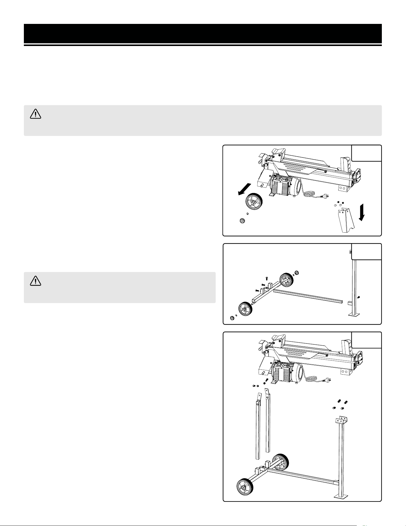
INSTALLING THE STAND
PREPARATION & ASSEMBLY
NOTE: Do not discard the box or any packing material until all parts are examined and accounted for. Inspect the
unit for shipping damage.
If any part of the log splitter is missing or damaged, do not plug in or operate the unit until the damaged part is
repaired or replaced. Please call 1-847-429-9263 for assistance.
WARNING! Lifting the log splitter is a two person operation. Once raised, make sure the log splitter is stable
before performing any assembly or maintenance.
WARNING! Installing the stand requires two people.
Do not attempt alone.
1. Two people are required for this job. Convince a good friend
or even a trustworthy foe to help before starting.
2. Place the log splitter horizontally on the floor. Prepare a
piece of padding for underneath the splitter.
3. Disassemble the wheels and support leg. Remove the
hub cap, and take off the wheels and support leg from the
machine’s body by removing the cotter pins (Fig. 2).
4. Assemble the stand. Using the cotter pins, attach the wheels
onto the wheel axis of the stand. Connect and secure the stand
together using M10x25 bolts (Fig. 3).
5. Install the log splitter onto the stand with M8x25 bolts, nuts
and washers (Fig. 4).
NOTE: Alternatively, you can carefully flip the unit over and
install the stand upside down. Make sure the bleed valve and
all seals are tight before you flip the log splitter. This will help
you insert the bolt for the rear legs as the space is very tight.
Woodster GmbH - D-89335 Ichenhausen - Tel. 08223/4002 0 - Fax 08223/4002 20
1
2
3
4
390 5202 003
Fig. 2
Woodster GmbH - D-89335 Ichenhausen - Tel. 08223/4002 0 - Fax 08223/4002 20
1
2
3
4
390 5202 003
Fig. 3
Woodster GmbH - D-89335 Ichenhausen - Tel. 08223/4002 0 - Fax 08223/4002 20
1
2
3
4
390 5202 003
Fig. 4
9
OPERATION
WARNING! Read and thoroughly understand all instructions and safety information before operating this
log splitter. Failure to do so may cause serious injury or death. Do not allow anyone to operate this log splitter
who has not read this manual.
As with all power equipment, a log splitter can be dangerous if assembled or used improperly. Do not operate this
log splitter if you have doubts or questions concerning safe operation. Call our customer service department at
1-847-429-9263 to address these concerns.
CHECKING THE LEVEL OF HYDRAULIC FLUID
The hydraulic system is a closed system consisting of the fluid tank, fluid
pump and control valve. This log splitter has been filled with AW32 hydraulic
fluid during the manufacturing process. Before each operation, check the
hydraulic fluid and add more if the level is low.
1. Carefully lift up on the handle of log splitter so it is in the vertical position.
Make sure machine is stable and will not fall. Let it rest in this position for
about 2 minutes so the fluid level can be checked properly.
2. Remove the fluid drain bolt (Fig. 5 - 1) and use a clean rag to wipe the
dipstick clean of fluid. CAUTION: Hydraulic fluid might flow out.
3. Put dipstick back in the tank (without screwing) and pull it out again.
4. Check the fluid level on the dipstick. It should be between the two notches on the end of the dipstick and within
about 1/4 inch of the upper notch.
5. Add fluid if the level is low. Wipe off the dipstick and check the fluid level again. Do not overfill. Replace the
dipstick and tighten the fluid drain bolt.
6. Lower the log splitter back into the horizontal position. Check hydraulic connections and fittings regularly for
airtightness. Tighten when necessary.
Remember to use AW32 fluid for operation at temperatures above 40°F, and Dexron® automatic transmission fluid
for operation below 40°F.
Fig. 5
OPENING/CLOSING THE BLEED SCREW (FIG. 5)
1. Before operation: Always loosen the bleed screw prior to operation. Turn
the bleed screw (Fig. 6 - 1) counterclockwise one or two turns to allow air to
be released from the hydraulic system. While the log splitter is in use, there
should be a detectable flow of air through the bleed screw.
WARNING! Failure to release the bleed screw to release air from the
hydraulic system may damage the hydraulic seals, permanently damaging
the log splitter.
Fig. 6
1
1
WARNING! Lifting the log splitter is a two person operation. Once raised, make sure the log splitter is stable
before performing any maintenance.
10

OPERATION
PREPARING THE LOGS AND THE LOG SPLITTER
1. Ensure the equipment is in safe working condition. Operate the unit without loading any logs to make sure it is
working normally. Check that all nuts, bolts and hydraulic fittings are tight. Check the switch, power cable and plug
for damage to avoid electric shock.
2. Plug in the power cable. Make sure you have an extension cord that can handle the full 15A of this unit. The power
supply for this log splitter must have a protection device (circuit breaker) for over or under voltage.
3. Make sure the log is prepared and suitable for use with this machine. Make sure:
- There are no nails or foreign objects in the log
- The ends of the log are cut square
- The log can rest flat in the cradle
- The log should be no longer than 21 inches with a diameter of less than 10 inches.
WARNING! Never try to split logs larger than the rated capacity of the tool. Attempting to do so could result
in personal injury and damage to the tool.
4. Place the log securely on the beam against the splitting wedge. Make sure logs will not twist, rock or slip while
being split. Logs should be cut with square ends and a maximum length of 20.5 inches.
SPLITTING THE LOG
1. The log splitter is equipped with a two-handed safety that requires both hands for operation. If either control is
released, the log splitter will stop operating.
2. Press and hold the ON/OFF push button with your right hand. Allow enough time for the motor to speed up.
3. Push down on the hydraulic control lever with your left hand to initiate the splitting wedge.
CAUTION! Do not attempt to split two logs at the same time. One of them may fly up and hit you.
WARNING! If the log does not begin to split after 5 seconds of operation, release both controls. Otherwise,
the motor or hydraulic fluid may overheat and damage the machine. Roll difficult logs by 90° to see whether they
can be split in a different direction. If the log fails to split, this indicates that its hardness exceeds the capacity of
the machine and thus should be discarded to protect the log splitter.
4. Release the ON/OFF button and the control lever once the log is split. The push rod will then retract.
5. When finished splitting the logs, unplug the power cord and close the bleed screw.
11
OPERATION
REMOVING JAMMED LOG
WARNING! Do not attempt to remove a jammed log with your hands.
Do not try to knock off the jammed log (Fig. 7). Doing so may cause in-
jury and damage the splitter.
1. Release both controls.
2. After the ram moves back and completely stops at its starting position,
insert a wooden wedge under the jammed log (Fig. 8 - 1).
2. Start log splitter to push the wooden wedge under the jammed one.
3. Repeat the above procedures with a steeper slope of wedge until the log
is completely free.
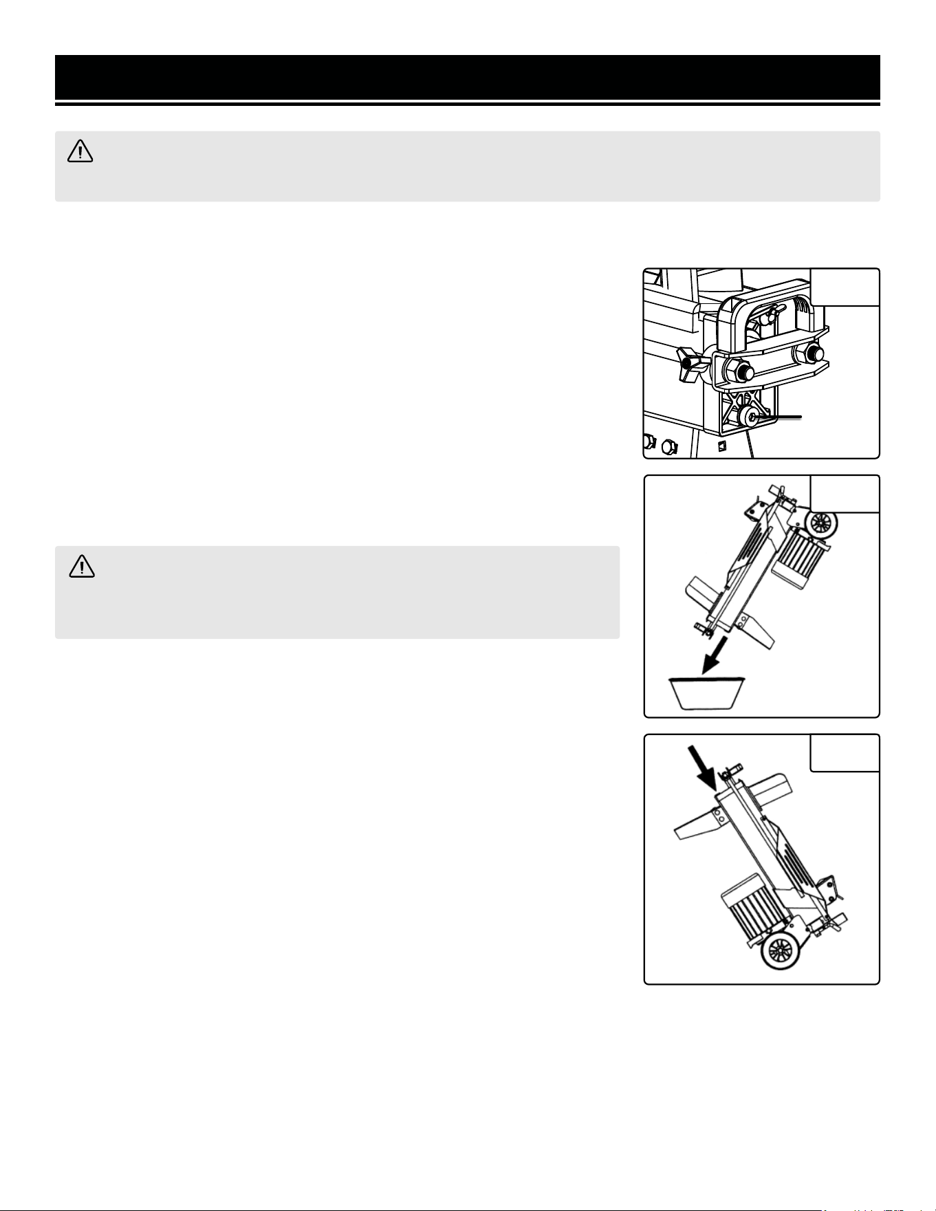
RAM LIMITING
When splitting short material you can use the ram limiting ring to set the
distance the ram will retract. This allows shorter travel times for the ram
during use.
16
Das Loslassen eines der Bedienteile führt zum sofortigen
Stopp der Maschine. Das Loslassen beider Bedienteile
führt dazu, dass die Druckplatte zurückgefahren wird.
Ist das Gerät innerhalb 5 Sekunden nicht in der Lage,
ein Stück Spaltgut zu spalten, stoppen Sie den Vorgang
unverzüglich. Das Spaltgut ist wahrscheinlich zu hart für
die Kapazität Ihrer scheppach Maschine. Drehen Sie das
Spaltgut um 90° und versuchen es noch einmal. Vorsicht:
bei andauerndem Betrieb von mehr als 5 Sekunden droht
Überhitzung das Gerät zu beschädigen.
Hubbegrenzung, Fig. 1.1
Bei kurzem Spaltgut ist es sinnvoll, den Hub der Druck-
platte 2 zu begrenzen. Dazu drücken Sie den Hydrau-
likhebel 10 und den Auslöseknopf 7 und fahren mit der
Druckplatte 2 bis kurz vor das Spaltgut.
Nun lassen Sie den Auslöseknopf los, stellen den Hubbe-
grenzungsring 13 an das Gehäuse und ziehen ihn fest.
Anschließend können sie den Hydraulikhebel wieder los-
lassen.
Die Druckplatte bleibt nun an der gewählten Position ste-
hen.
Fehlerhafte Bestückung, Fig. 2
Legen Sie Spaltgut immer plan auf die Auageäche! Es
darf nicht verrutschen oder sich schräg stellen lassen.
Der Spaltkeil wird überstrapaziert, wenn ein Spaltvor-
gang nicht auf der gesamten Schneide, sondern nur im
oberen Bereich erfolgt.
Spalten Sie niemals mehrere Stücke gleichzeitig! Es be-
steht die Gefahr, dass eines der Teile unkontrollierbare
Beschleunigung erfährt. Hohe Verletzungsgefahr!
Verkeiltes Spaltgut, Fig. 3, 4
Versuchen Sie niemals, verkeiltes Spaltgut aus Ihrer
scheppach Maschine heraus zu klopfen. Dies kann zu
Unfällen und Beschädigungen am Gerät führen. Gehen
Sie wie folgt vor:
1. Lassen Sie die Druckplatte in die Startposition zurück-
fahren.
2. Legen Sie einen Keil unter das Spaltgut wie in der Ab-
bildung gezeigt.
2. Lösen Sie einen Spaltvorgang aus, sodass die Druck-
platte den Keil weit unter das herauszulösende Spalt-
gut schiebt.
2. Wiederholen Sie die oberen Schritte mit neuen Keilen
so lange, bis das Spaltgut nach oben aus der Maschi-
ne geschoben wird.
Hydraulik/Ölwechsel
Die Hydraulikanlage ist ein geschlossenes System mit
Öltank, Ölpumpe und Steuerventil. Es darf nicht verän-
dert oder manipuliert werden.
Anschlüsse und Verschraubungen regelmäßig auf Dicht-
heit prüfen, bei Bedarf nachziehen.
Der Öltank ist werksseitig mit hochwertigem Hydrauliköl
gefüllt.
Fig. 5
Fig. 6
Fig. 4
Fig. 2
Fig. 3
Fig. 7
16
Das Loslassen eines der Bedienteile führt zum sofortigen
Stopp der Maschine. Das Loslassen beider Bedienteile
führt dazu, dass die Druckplatte zurückgefahren wird.
Ist das Gerät innerhalb 5 Sekunden nicht in der Lage,
ein Stück Spaltgut zu spalten, stoppen Sie den Vorgang
unverzüglich. Das Spaltgut ist wahrscheinlich zu hart für
die Kapazität Ihrer scheppach Maschine. Drehen Sie das
Spaltgut um 90° und versuchen es noch einmal. Vorsicht:
bei andauerndem Betrieb von mehr als 5 Sekunden droht
Überhitzung das Gerät zu beschädigen.
Hubbegrenzung, Fig. 1.1
Bei kurzem Spaltgut ist es sinnvoll, den Hub der Druck-
platte 2 zu begrenzen. Dazu drücken Sie den Hydrau-
likhebel 10 und den Auslöseknopf 7 und fahren mit der
Druckplatte 2 bis kurz vor das Spaltgut.
Nun lassen Sie den Auslöseknopf los, stellen den Hubbe-
grenzungsring 13 an das Gehäuse und ziehen ihn fest.
Anschließend können sie den Hydraulikhebel wieder los-
lassen.
Die Druckplatte bleibt nun an der gewählten Position ste-
hen.
Fehlerhafte Bestückung, Fig. 2
Legen Sie Spaltgut immer plan auf die Auageäche! Es
darf nicht verrutschen oder sich schräg stellen lassen.
Der Spaltkeil wird überstrapaziert, wenn ein Spaltvor-
gang nicht auf der gesamten Schneide, sondern nur im
oberen Bereich erfolgt.
Spalten Sie niemals mehrere Stücke gleichzeitig! Es be-
steht die Gefahr, dass eines der Teile unkontrollierbare
Beschleunigung erfährt. Hohe Verletzungsgefahr!
Verkeiltes Spaltgut, Fig. 3, 4
Versuchen Sie niemals, verkeiltes Spaltgut aus Ihrer
scheppach Maschine heraus zu klopfen. Dies kann zu
Unfällen und Beschädigungen am Gerät führen. Gehen
Sie wie folgt vor:
1. Lassen Sie die Druckplatte in die Startposition zurück-
fahren.
2. Legen Sie einen Keil unter das Spaltgut wie in der Ab-
bildung gezeigt.
2. Lösen Sie einen Spaltvorgang aus, sodass die Druck-
platte den Keil weit unter das herauszulösende Spalt-
gut schiebt.
2. Wiederholen Sie die oberen Schritte mit neuen Keilen
so lange, bis das Spaltgut nach oben aus der Maschi-
ne geschoben wird.
Hydraulik/Ölwechsel
Die Hydraulikanlage ist ein geschlossenes System mit
Öltank, Ölpumpe und Steuerventil. Es darf nicht verän-
dert oder manipuliert werden.
Anschlüsse und Verschraubungen regelmäßig auf Dicht-
heit prüfen, bei Bedarf nachziehen.
Der Öltank ist werksseitig mit hochwertigem Hydrauliköl
gefüllt.
Fig. 5
Fig. 6
Fig. 4
Fig. 2
Fig. 3
Fig. 8
1. Press the hydraulic lever and the ON/OFF switch. Let the pressure
plate (Fig. 9 - 1) move just in front of the splitting material.
2. Release the ON/OFF switch but keep the lever pushed down. Mount
the ram limiting ring (Fig 9 - 2) to the stud and tighten it. This sets the
distance the ram will retract.
3. Release the hydraulic lever. The ram will retract back to the shortened
resting position. When finished cutting material of this length remove
the limiting ring and allow the ram to fully retract before storage.
Fig. 9
1
1
2
STORAGE
TRANSPORTING
To move the machine, use the handle on the front/top of the unit. Lift until the unit only rests on its wheels and roll
it to the desired jobsite or storage area. If the unit is on the stand, lift until the front leg comes off the ground and
roll the unit to the desired area.
STORAGE
Store the log splitter in a location away from sources of heat, open flames, sparks or pilot lights – such as water
heaters, space heaters, furnaces, clothes dryers, or other gas appliances. Your log splitter can be stored or
transported under ambient temperatures between -4° F and +140°F at a maximum humidity of 80%.
WARNING! Let the motor cool for at least five minutes before storing. A hot motor can be a fire hazard and
cause injury.
12
MAINTENANCE
Repair and maintenance work on the electrical system may only be carried out by a qualified electrician. All protective
safety devices must be reattached immediately after repair and maintenance work have been completed.
WARNING! Make sure the log splitter is disconnected from the power source before performing any repair
or maintenance.
WARNING! Lifting the log splitter is a two person operation. Once
raised, make sure the log splitter is stable before performing any mainte-
nance.
4. Raise the splitting edge end of the log splitter and make sure it is secure
before refilling the hydraulic fluid (Fig 12).
5. Pour approximately 3.7 quarts (0.9 gallons) of approved hydraulic fluid (AW32
hydraulic fluid for operation over 40°F or Dexron® automatic transmission
fluid for operation below 40°F) into the tank.
6. Check the fluid level with the dipstick. Make sure the level of the refilled fluid
is between the bottom two rings grooved into the base of the dipstick. Add
more fluid as necessary.
7. Replace the fluid drain knob (Fig. 10 - 1) and tighten securely. Return the log
splitter to horizontal position.
8. Periodically check fluid level and refill as needed.
SPLITTING WEDGE
The splitting wedge is a wearing part that may need to be sharpened or replaced
after prolonged use. Keep the splitting wedge clean of dirt, wood shavings,
bark, etc. Use a fine-toothed file or rasp to remove burrs or refresh crushed
areas to ensure optimal operation
LUBRICATION
Make sure all moving parts run smoothly. Lubricate with a few drops of oil
when necessary. Lubricate the slide rails with grease.
TO REPLACE THE HYDRAULIC FLUID
The hydraulic fluid should be replaced after 150 hours of use or every six
months.
1. Place a one gallon (or larger) pan under the splitting wedge end of the log
splitter.
2. Loosen the fluid drain knob (Fig. 10 - 1) and remove it. Be prepared for
hydraulic fluid to flow out.
3. Raise the motor end of the log splitter to allow the fluid to drain into the pan
(Fig. 11). Return the log splitter to horizontal position when the fluid is empty.
NOTE: Responsibly dispose of collected fluid at a public collection facility.
Fig. 10
Fig. 11
Fig. 12
1
13

Problem Possible Cause Action
Motor does not start
The motor is overloaded and circuit
breaker trips to protect the machine.
Wait for the motor to cool down. Reduce the
load and press the circuit breaker to reset.
Logs will not split
Extension cord is too long or gauge
is too low.
Check extension cord to ensure the gauge of
the cord is 12 or 14 AWG and that the cord
length does not exceed 25 ft.
Incorrect positioning of the log.
Make sure the log is properly positioned on
the worktable (see page 11 “Operation” section
and reload the log).
The size, hardness, or density of the
log may exceed the capacity of the
splitter.
Reduce the log size before placing it on the
splitter.
Splitting wedge cutting edge is blunt
or dull.
Sharpen the wedge.
The bleed screw was not loosened
and air is trapped in the hydraulic
tank.
Loosen the bleed screw one or two turns.
The hydraulic fluid is low and may
need to be replenished.
Check the hydraulic fluid level and refill as
needed (see page 10, “Checking the Level of
Hydraulic Fluid”).
The maximum pressure limiting ad-
justment setting has changed.
Contact a customer service technician at 1-847-
429-9263.
Hydraulic fluid leaks
The bleed screw is not tightened be-
fore transporting the log splitter.
Tighten the bleed screw before moving the log
splitter.
The bleed screw was not loosened
before operation and air is trapped
in the hydraulic tank
Loosen the bleed screw by one or two turns.
The fluid drain knob may be loose.
Tighten the fluid drain knob using a 8mm hex
wrench.
The hydraulic control valve assem-
bly and/or seals may be worn.
Contact a customer service technician at 1-847-
429-9263.
Ram moves jerkily,
creating unfamiliar
noises or excessive
vibration
Lack of hydraulic fluid and excessive
air in the hydraulic system
Check the hydraulic fluid level and refill as
needed (See page 10, “Checking the Level of
Hydraulic Fluid”).
TROUBLESHOOTING GUIDE
WARNING! Stop using the generator immediately if any of the following problems occur or risk serious
personal injury. If you have any questions, please contact customer service at 1-847-429-9263 (M-F 8-5 CST),
or email [email protected].
14
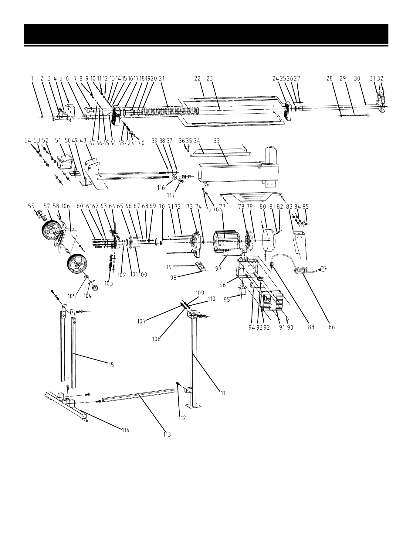
EXPLODED VIEW & PARTS LIST
15
NOTE: Not all parts may be available for purchase. Parts and accessories that wear down over the course of
normal use are not covered under the warranty.

No. Part No. Name Qty
1 56207-001 Lever Mount Nut 1
2 56207-002 Domed Cap Nut 3
3 56207-003 Lever 1
4 56207-004 Lever Knob 1
5 56207-005 Guard Plate 1
6 56207-006 Nut 2
7 56207-007 Copper Gasket 4
8 56207-008 Screw 1
9 56207-009 O-ring 1
10 56207-010 Snap Washer – Shaft 1
11 56207-011 Valve Spring 1
12 56207-012 O-ring 1
13 56207-013 Valve Core Rod 1
14 56207-014 Sliding Pressure Sensor Sleeve 1
15 56207-015
Sliding Pressure Sensor Sleeve
Spring
1
16 56207-016 Aluminum Cover ( Rear ) 1
17 56207-017 O-ring 1
18 56207-018 Piston 1
19 56207-019 Piston Ring 1
20 56207-020 O-ring 1
21 56207-021 Spring 1
22 56207-022 Stud 4
23 56207-023 Hydraulic Cylinder 1
24 56207-024 Aluminum Cover ( Front) 1
25 56207-025 Piston Rod Seal 1
26 56207-026 O-ring 1
27 56207-027 Bleed Screw 1
28 56207-028 Washer 1
No. Part No. Name Qty
29 56207-029 Dipstick 1
30 56207-030 Piston Rod 1
31 56207-031 Lift Handle 1
32 56207-032 Screw 2
33 56207-033 Frame Beam 1
34 56207-034 Log Cradle 2
35 56207-035 Spring Washer 4
36 56207-036 Screw 6
37 56207-037 Nut 2
38 56207-038 Flat Washer 2
39 56207-039 Nut 2
40 56207-040 Nut Plug 1
41 56207-041 Washer 1
42 56207-042 Valve Sleeve 1
43 56207-043 Spring 5
44 56207-044 Adjustment Screw 1
45 56207-045 Steel Ball 1
46 56207-046 Pressure Limited Valve Spring 1
47 56207-047 Adjusting Screw 1
48 56207-048 Ram Mounting Bracket 1
49 56207-049 Plastic Insert 1
50 56207-050 Plastic Insert 2 1
51 56207-051 Log Ram 1
52 56207-052 Nut 4
53 56207-053 Flat Washer 5
54 56207-054 Screw 4
55 56207-055 Wheel cover 2
57 56207-057 Wheel 2
58 56207-058 Washer 2
EXPLODED VIEW & PARTS LIST
16
NOTE: Not all parts may be available for purchase. Parts and accessories that wear down over the course of
normal use are not covered under the warranty.

No. Part No. Name Qty
60 56207-060 Bolt 6
61 56207-061 Spring Washer 9
62 56207-062 Washer 9
63 56207-063 Gear Pump Cover 1
64 56207-064 Spring 2
65 56207-065 Gear Housing Plate 1
66 56207-066 Circlip 2
67 56207-067 Gear Shaft 1
68 56207-068 Steel Ball 1
69 56207-069 Gear 2
70 56207-070 Pin 1
71 56207-071 Washer 6
72 56207-072 Bolt 3
73 56207-073 Motor Cover 1
74 56207-074 Seal 1
75 56207-075 Nut 1
76 56207-076 Screw 1
77 56207-077 Motor 1
78 56207-078 Fan 1
79 56207-079 Block turn 1
80 56207-080 Shroud 1
81 56207-081 Spring Washer 6
82 56207-082 Screw 2
83 56207-083 Leg 1
84 56207-084 Nut 5
85 56207-085 Bolt 5
86 56207-086 Cable & plug 1
88 56207-088 Cable Grommet 1
No. Part No. Name Qty
90 56207-090 Screw 11
91 56207-091 Switch Box cover 1
92 56207-092 Airproof Underlay 1
93 56207-093 Connection Terminal 1
94 56207-094 Capacitor 1
95 56207-095 Switch 1
96 56207-096 Switch Box 1
97 56207-097 Waterproof Seal 1
98 56207-098 Motor Support Left Shoe 1
99 56207-099 Motor Support Right Shoe 1
100 56207-100 Pin 2
101 56207-101 Spring 2
102 56207-102 Sliding Sleeve 4
103 56207-103 Bolt 3
104 56207-104 Cotter Pin 2
105 56207-105 Washer 2
106 56207-106 Wheel Bracket 1
107 56207-107 Bolt 6
108 56207-108 Nut 6
109 56207-109 Washer 6
110 56207-110 Spring Washer 6
111 56207-111 Front Stand Leg 1
112 56207-112 Bolt 4
113 56207-113 Stand Connection Member 1
114 56207-114 Rear Stand Bottom 1
115 56207-115 Rear Stand Legs 2
116 56207-116 Ram Limiting Ring 1
117 56207-117 Star Handle 1
EXPLODED VIEW & PARTS LIST
17
NOTE: Not all parts may be available for purchase. Parts and accessories that wear down over the course of
normal use are not covered under the warranty.

WARRANTY STATEMENT
18
WEN Products is committed to building tools that are dependable for years. Our warranties are consistent with this
commitment and our dedication to qualit
y.
LIMITED WARRANTY OF WEN PRODUCTS FOR HOME USE
GRE
AT LAKES TECHNOLOGIES, LLC (“Seller”) warrants to the original purchaser only, that all WEN
consumer
power tools will be free from defects in material or workmanship during personal use for a period of two (2) years
used
for professional or commercial use. Purchaser has 30 days from the date of purchase to report missing or
damaged parts.
SELLER’S
SOLE OBLIGATION AND YOUR EXCLUSIVE REMEDY under this Limited Warranty and, to the extent per-
mitted
by law, any warranty or condition implied by law, shall be the replacement of parts, without charge, which a
re
defective
in material or workmanship and which have not been subjected to misuse, alteration, careless handling,
misrepair
, abuse, neglect, normal wear and tear,
improper maintenance, or other conditions adversely affecting the
Product
or the component of the Product, whether by accident or intentionally, by persons other than Seller. To
make
a claim under this Limited Warranty, you must make sure to keep a copy of your proof of purchase that
clearly
-
dor
of Great Lakes Technologies, LLC. Purchasing through third party vendors, including but not limited to garage
sales,
pawn shops, resale shops, or any other secondhand merchant, voids the warranty included with this
product.
Contact [email protected] or 1-847-429-9263 with the following information to make arrangements:
your
shipping address, phone number, serial number, required part numbers, and proof of purchase. Damaged
or
defective parts and products may need to be sent to WEN before the replacements can be shipped out.
-
turning
a product for warranty service, the shipping charges must be prepaid by the purchaser. The product
must
be
shipped in its original container (or an equivalent), properly packed to withstand the hazards of shipment. The
product
must be fully insured with a copy of the proof of purchase enclosed. There must also be a description of
the
will be returned and shipped back to the pur
chaser at no charge for addresses within the contiguous United States.
THIS
LIMITED WARRANTY DOES NOT APPLY TO ITEMS THAT WEAR OUT FROM REGULAR USAGE OVER TIME,
INCLUDING
BELTS, BRUSHES, BLADES, BATTERIES, ETC. ANY IMPLIED WARRANTIES SHALL BE LIMITED IN
DUR
ATION TO TWO (2) YEARS FROM DATE OF PURCHASE. SOME STATES IN THE U.S. AND SOME CANADIAN
PROVINCES
DO NOT ALLOW LIMITATIONS ON HOW LONG AN IMPLIED WARRANTY LASTS, SO THE ABOVE LIMI-
TAT
ION MAY NOT APPLY TO YOU.
IN
NO EVENT SHALL SELLER BE LIABLE FOR ANY INCIDENTAL OR CONSEQUENTIAL DAMAGES (INCLUDING
BUT
NOT LIMITED TO LIABILITY FOR LOSS OF PROFITS) ARISING FROM THE SALE OR USE OF THIS PRODUCT.
SOME ST
ATES IN THE U.S. AND SOME CANADIAN PROVINCES DO NOT ALLOW THE EXCLUSION OR LIMITAT
ION
OF
INCIDENTAL OR CONSEQUENTIAL DAMAGES, SO THE ABOVE LIMITATION OR EXCLUSION MAY NOT APPLY
TO YOU.
THIS
LIMITED WARRANTY GIVES YOU SPECIFIC LEGAL RIGHTS, AND YOU MAY ALSO HAVE OTHER RIGHTS
WHICH
VARY FROM STATE TO STATE IN THE U.S., PROVINCE TO PROVINCE IN CANADA AND FROM COUNTRY
TO COUNT
RY.
THIS
LIMITED WARRANTY APPLIES ONLY TO ITEMS SOLD WITHIN THE UNITED STATES OF AMERICA, CANA-
DA
AND THE COMMONWEALTH OF PUERTO RICO. FOR WARRANTY COVERAGE WITHIN OTHER
COUNTRIES,
CONT
ACT THE WEN CUSTOMER SUPPORT LINE. FOR WARRANTY PARTS OR PRODUCTS REPAIRED UNDER
W
ARRANTY SHIPPING TO ADDRESSES OUTSIDE OF THE CONTIGUOUS UNITED STATES, ADDITIONAL
SHIPPING
CHARGES MAY APPLY.

NOTES
19

THANKS FOR
REMEMBERING
V. 2023.02.27
