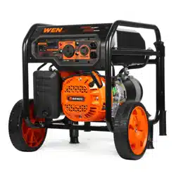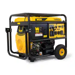
13KW PORTABLE
GENERATOR
Your new tool has been engineered and manufactured to WEN’s highest standards for dependability, ease
of operation, and operator safety. When properly cared for, this product will supply you years of rugged,
trouble-free performance. Pay close attention to the rules for safe operation, warnings, and cautions. If you
use your tool properly and for its intended purpose, you will enjoy years of safe, reliable service.
IMPORTANT:
NEED HELP? CONTACT US!
Have product questions? Need technical support?
Please feel free to contact us at:
800-232-1195
WENPRODUCTS.COM
(M-F 8AM-5PM CST)
Model # 5613K
bit.ly/wenvideo
For replacement parts visit
WENPRODUCTS.COM
NOTICE: Please refer to wenproducts.com for the most up-to-date instruction manual.

TABLE OF CONTENTS
2
Generator Identification
3
3
4
4
5
6
7
10
13
15
15
17
20
23
24
25
26
32
33
Service Record
Introduction
Safety Information
General Safety Procedures
Important Safety Instructions
Generator Components
Generator Preparation
Starting the Generator
Stopping the Generator
Subsequent Starting of the Generator
Using the Generator
Maintenance & Care
Storage & Transport
Specifications
Troubleshooting
Exploded View and Parts List
Wiring Diagram
Warranty Statement
If assistance for information or service is required, please contact the Customer Service Help Line by calling
800-232-1195; customer will be asked to provide generator information when calling.
Refer to the illustration below for the location of the serial number. Record generator information in the spaces
provided below.
DATE OF PURCHASE: ______________________________________________
PURCHASED FROM: ______________________________________________
GENERATOR MODEL NUMBER: 5613K
ENGINE SERIAL NUMBER: _________________________________________
SERVICE RECORD
Record Service Dates:
Date Date Date Date Date Date
Change Oil
Change Spark Plug
Clean Fuel Tank
Clean Air Filter
Charge battery
(run the generator)
Change Oil Filter
3
GENERATOR IDENTIFICATION
Serial Number
TO MAXIMIZE THE LIFESPAN OF THIS GENERATOR, MAKE SURE TO RUN IT
AT LEAST ONCE A MONTH. IF YOU DO NOT RUN IT OFTEN, IT WILL GREAT-
LY SHORTEN THE LIFESPAN AND PERFORMANCE OF THE GENERATOR.
4
INTRODUCTION
SAFETY INFORMATION
Thank You for Purchasing a WEN® Product. This manual provides information regarding the safe operation
and maintenance of this product. Every effort has been made to ensure the accuracy of the information in this
manual. WEN® reserves the right to change this product and specifications at any time without prior notice.
Please keep this manual available to all users during the entire life of the generator.
This manual contains special messages to bring attention to potential safety concerns, gen-
erator damage as well as helpful operating and servicing information. Please read all the
information carefully to avoid injury and machine damage.
QUESTIONS? PROBLEMS?
In order to answer questions and solve problems in the most efficient and speedy manner, contact Customer
Service at (800) 232-1195, M-F 8-5 CST
NOTICE REGARDING EMISSIONS
Engines that are certified to comply with U.S. EPA emission regulations for SORE (Small Off Road Equipment),
are certified to operate on regular unleaded gasoline, and may include the following emission control systems:
(EM) Engine Modifications and (TWC) Three-Way Catalyst (if so equipped).
Before operating this generator read and observe all warnings, cautions, and instructions on the generator and in
this Owner’s Manual.
NOTE: The following safety information is not meant to cover all possible conditions and situations that may oc-
cur. Read the entire Owner’s Manual for safety and operating instructions. Failure to follow instructions and safety
information could result in serious injury or death.
This safety alert symbol is used to identify safety information about hazards that can result in personal injury.
A signal word (DANGER, WARNING, or CAUTION) is used with the alert symbol to indicate the
likelihood and the potential severity of injury. In addition, a hazard symbol may be used to represent
the type of hazard.
DANGER indicates a hazard, which, if not avoided, will result in death or serious injury.
WARNING indicates a hazard, which, if not avoided, could result in death or serious injury.
CAUTION indicates a hazard, which, if not avoided, might result in minor or moderate injury.
CAUTION when used without the alert symbol, indicates a situation that could result in damage to the engine or
generator.
5
For any questions regarding the hazard and safety notices listed in this manual or on the product, please call (800)
232-1195 M-F 8-5 CST before using the generator.
DANGER: CARBON MONOXIDE
Using a generator indoors CAN KILL YOU IN MINUTES. Generator exhaust contains carbon monoxide (CO).
This is a poison gas you cannot see or smell. If you can smell the generator exhaust, you are breathing CO. But
even if you cannot smell the exhaust, you could be breathing CO.
NEVER use a generator inside homes, garages, crawlspaces, or other partly enclosed areas. Deadly levels
of carbon monoxide can build up in these areas. Using a fan or opening windows and doors does NOT
supply enough fresh air. ONLY use a generator outside and far away from windows, doors, and vents. These open-
ings can pull in generator exhaust.
Even if you use a generator correctly, CO may leak into the home. ALWAYS use a battery-powered or battery-
backup CO alarm in the home. If you start to feel sick, dizzy, or weak after the generator has been running, move
to fresh air RIGHT AWAY. See a doctor. You may have carbon monoxide poisoning.
WARNING: The exhaust from this product contains chemicals known to the State of California to cause
cancer, birth defects, or other reproductive harm.
WARNING: This generator may emit highly flammable and explosive gasoline vapors, which can cause
severe burns or even death if ignited. A nearby open flame can lead to explosion even if it isn’t directly in
contact with gasoline.
• Do not operate near an open flame.
• Do not smoke near generator.
• Always operate on a firm, level surface.
• Always turn generator off before refueling. Allow generator to cool for at least 2 minutes before removing
fuel cap. Loosen cap slowly to relieve pressure in tank.
• Do not overfill fuel tank. Gasoline may expand during operation. Do not fill to the top of the tank. Allow
for expansion.
• Always check for spilled fuel before operating.
• Empty fuel tank before storing or transporting the generator.
WARNING: This generator produces powerful voltage, which can result in electrocution.
• ALWAYS ground the generator before using it (see the “Ground the Generator” portion of the
“GENERATOR PREPARATION” section).
• Generator should only be plugged into electrical devices, either directly or with an extension cord.
NEVER connect to a building electrical system without a qualified electrician. Such connections must
comply with local electrical laws and codes. Failure to comply can create a back-feed, which may result
in serious injury or death to utility workers.
• Use a ground fault circuit interrupter (GFCI) in highly conductive areas such as metal decking or steel
work. GFCIs are available in-line with some extension cords.
• Do not use in rainy conditions.
• Do not touch bare wires or receptacles (outlets).
• Do not allow children or non-qualified persons to operate.
GENERAL SAFETY PROCEDURES

6
WARNING: This generator produces heat when running. Temperatures near exhaust can exceed 150
0
F (65
0
C).
Do not touch hot surfaces. Pay attention to warning labels on the generator identifying hot parts of the
machine.
Allow generator to cool down after use before touching engine or areas of the generator that become
hot during use.
CAUTION: Misuse of this generator can damage it or shorten its life.
Only use generator for its intended purposes.
Operate only on dry, level surfaces.
Allow generator to run for several minutes before connecting electrical devices.
Shut off and disconnect any malfunctioning devices from generator.
Do not exceed the wattage capacity of the generator by plugging in more electrical devices than the unit can
handle.
Do not turn on electrical devices until after they are connected to the generator.
Turn off all connected electrical devices before stopping the generator.
Turn the engine switch to “OFF” position when the engine is not running.
IMPORTANT SAFETY INSTRUCTIONS
SAVE THESE INSTRUCTIONS – This manual contains important instructions for the WEN
®
generator that
should be followed during installation and maintenance of the generator.
Generators vibrate in normal use. During and after the use of the generator, inspect both the generator as well as
extension and power supply cords for damage resulting from vibration. Have damaged items repaired or replaced
as necessary. Do not use plugs or cords that show signs of damage such as broken or cracked insulation.
For power outages, permanently installed stationary generators are better suited for providing backup power to the
home. Even a properly connected portable generator can become overloaded. This may result in overheating or
stressing of the components, possibly leading to a generator failure.
WARNING: If this generator is used as a supply for a building’s wiring system, the generator must be installed
by a qualified electrician and connected to a transfer switch as a separately derived system in accordance with
the National Electrical Code, NFPA 70. The generator shall be connected to a transfer switch that switches all
conductors excluding the equipment grounding conductor. The frame of the generator shall be connected to an
approved grounding electrode.
GENERAL SAFETY PROCEDURES
7
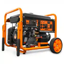
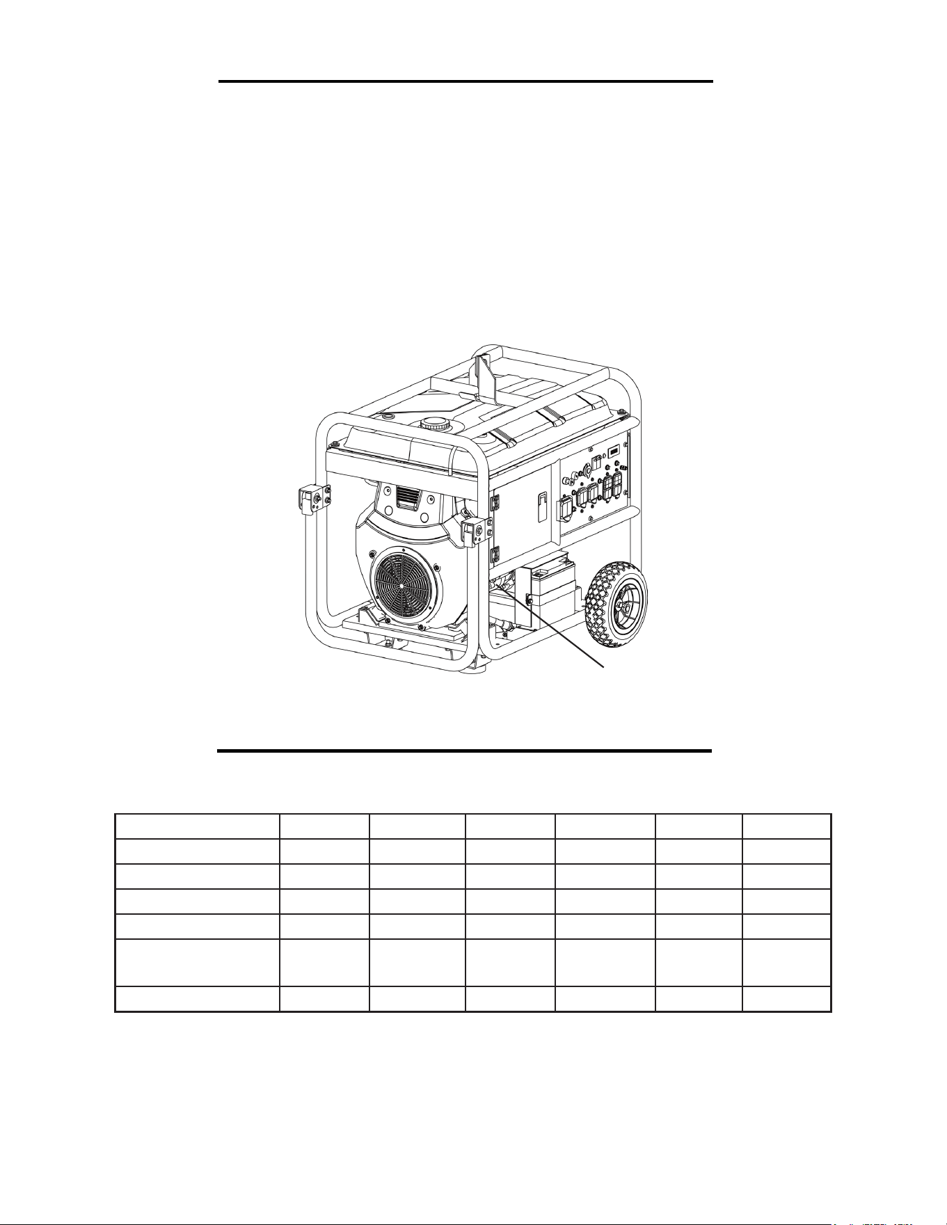
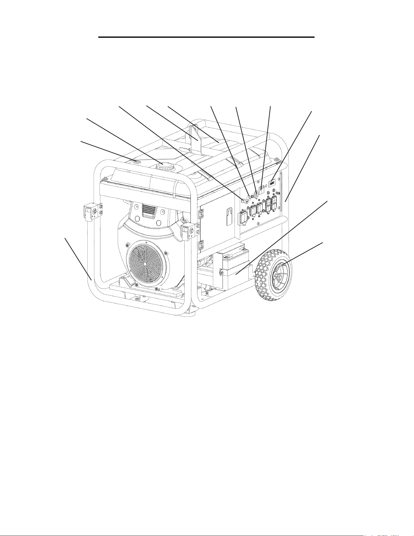
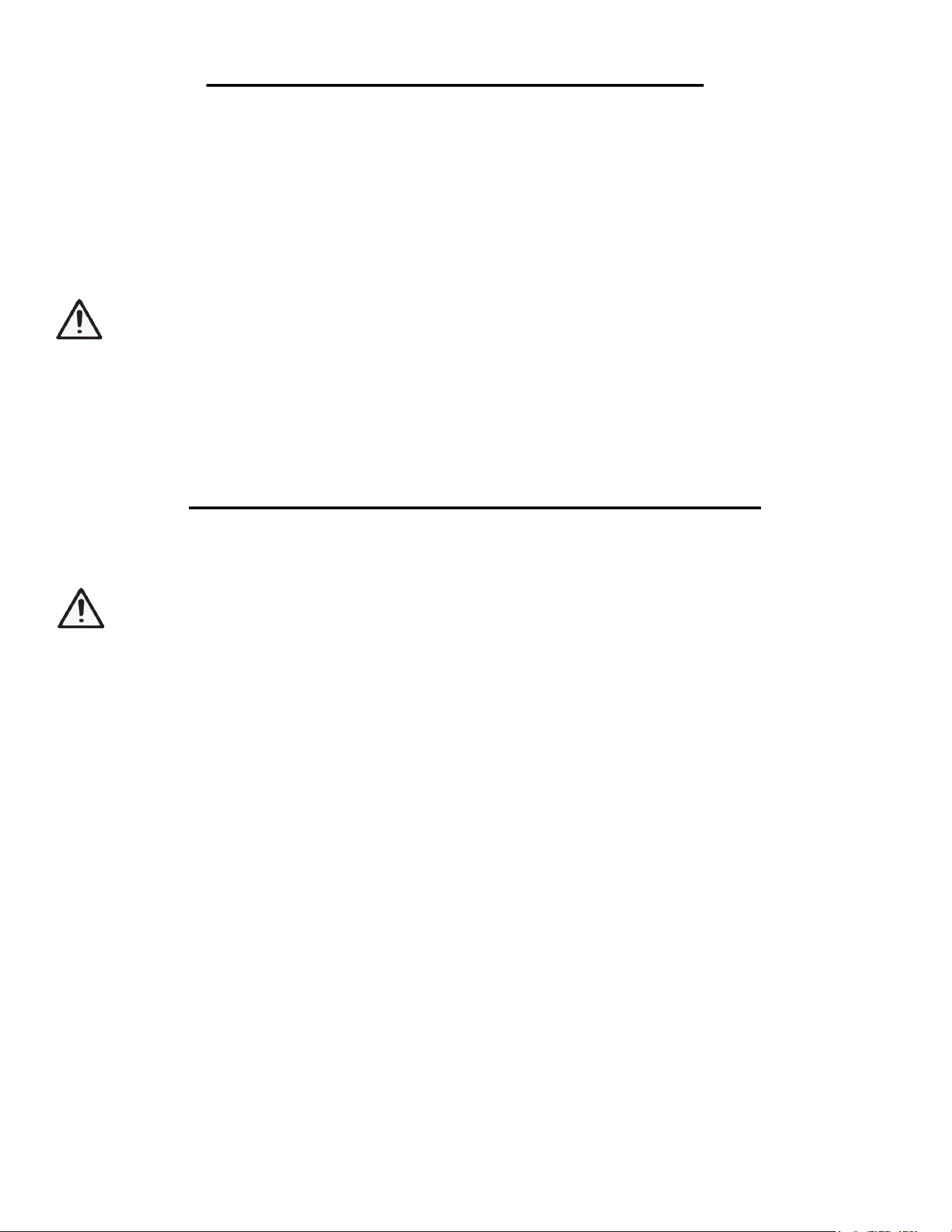
Use the illustrations below to become familiar with the locations and functions of the various components and
controls of this generator.
GENERATOR COMPONENTS
2
1
2
3
4
5
6
7
Handle
Fuel Gauge
Fuel Tank Cap
Choke Lever
Hook
Fuel Tank
Switch
8
9
10
11
12
13
12 V DC Receptacle
Circuit Breaker
Hour Meter
Frame
Battery
Wheel
1
4
5
6
7
8
9
10
11
12
13
3
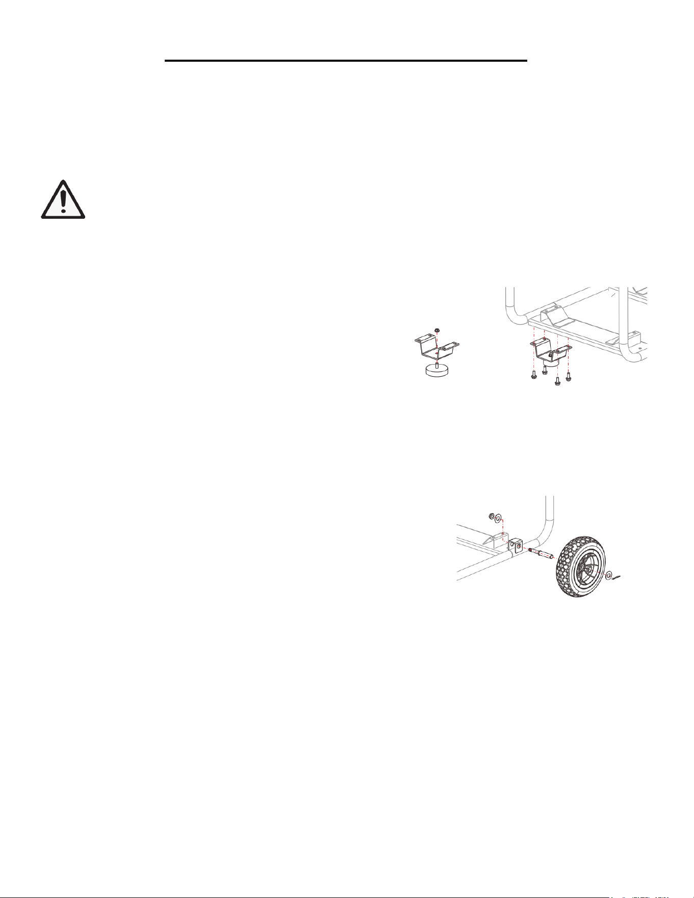
ASSEMBLY
In order to best protect the generator while in the package, this product comes with some components disassem-
bled. Please complete the following assembly steps before proceeding to use the generator. For ease of assembly,
we recommend attaching the components in the order listed in this manual.
If after reading this section, you are unsure about how to perform any of the steps, please call (800) 232-1195 M-F
8-5 CST for customer service.
WARNING: This generator is heavy. Assembly procedures may require lifting equipment or two
people.
ATTACH FEET
To attach the feet to the generator, perform the following
steps:
1. Find a wooden block or a similarly sturdy item that is at
least three inches thick. Stack the end of the generator with
the recoil starter onto the wooden block.
2. Setup both side feet as attached picture.
ATTACH WHEELS
To attach the wheels to the generator, perform the following steps:
1. Rest the exhaust end of the generator on the same wooden block
used for attaching the feet.
2. Take one wheel shaft and one nut as shown. Slide the wheel shaft
with the threaded part facing inward through the frame. Secure using
the nut and a wrench.
3. Slide the wheel onto the axle and secure in place using a large cotter
pin. Spread the pin legs apart slightly to help secure the pin in place.
4. Repeat steps 2 and 3 for the other wheel.
8
ASSEMBLY
ATTACH HANDLES
The handles attach to the generator frame on the same side as the recoil starter (left side when facing control
panel). To attach the handles to the generator frame, perform the following steps:
1. Take one handle bracket and line up the holes in the handle bracket with the holes on the generator frame.
2. Slide two bolts through the holes in the handle bracket and generator frame to hold the handle onto the frame.
3. Secure the bolt in place with a nut.
4. Set up the hand on the handle bracket.
5. Repeat steps 1-4 for the other handle.
Handle Bracket
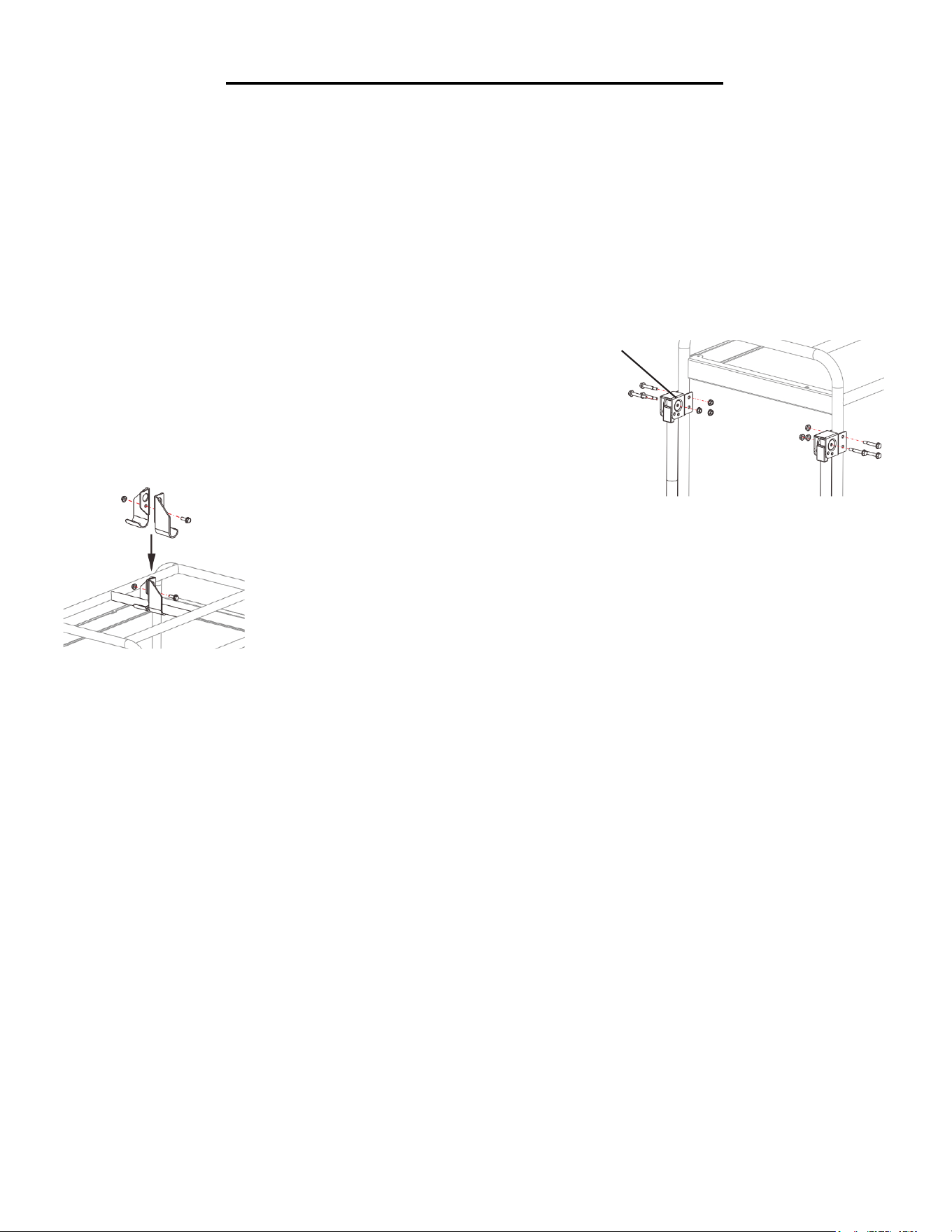
ATTACH HOOK
1. Attach the hooks to either side of the top center bar.
2. Fasten in place with a screw and bolt as shown in the figure to the left.
9
10
USING THE GENERATOR FOR THE FIRST TIME
The following section describes steps necessary to prepare the generator for use. If after reading this sec-
tion, you are unsure about how to perform any of the steps please call (800) 232-1195 M-F 8-5 CST for
customer service. Failure to perform these steps properly can damage the generator or shorten its life.
Step 1 - ADD OIL
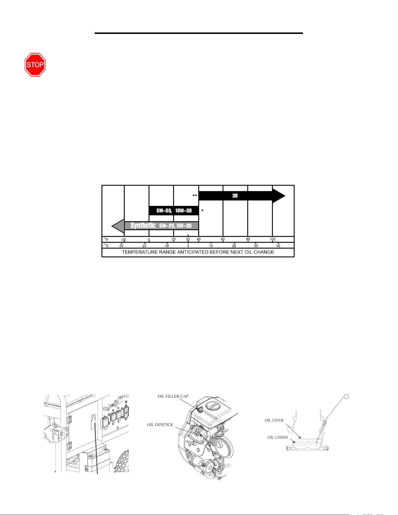
The generator is shipped without oil. User must add the proper amount of oil before operating the generator for
the first time. The oil capacity of the engine crankcase is 50.7 fl. oz. For general use (above 40° F), we recommend
30W, 4-stroke engine oil.
ENGINE OIL RECOMMENDATIONS
Select good quality detergent oil bearing the American Petroleum Institute (API) service classifications SJ, SL, or
SM (synthetic oils may be used). Use the ASE viscosity grade of oil from the following chart (Figure 1) that matches
the starting temperature anticipated before the next oil changes.
Figure 1 - Engine Oil Temperature Recommendations
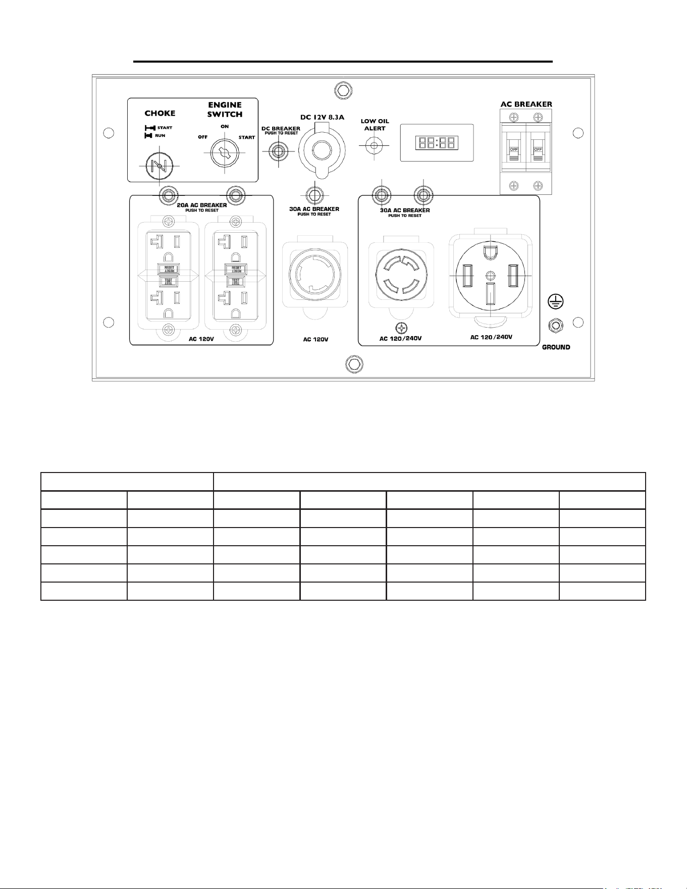
To add oil, follow these steps:
1. Make sure the generator is on a level surface. Tilting the generator to assist in filling will cause oil to flow into
engine areas and will cause damage. Keep generator level!
2. Open the door.
3. Remove the dipstick from the engine. (Figure 2)
4. Using a funnel or appropriate dispenser, add the correct amount of oil (50.7 fl.oz) into the crankcase. The
engine is equipped with a low oil sensor and will not start if the amount of oil is insufficient.
5. To check the oil level, wipe the dipstick with a clean rag. Insert the dipstick into the oil fill opening without
screwing it in. Remove the dipstick to check the oil mark.
6. Slowly add more oil and repeat step 4 until the oil mark reaches to the top of the dipstick (Figure 2). Do not
overfill the crankcase. The generator is equipped with a low-oil sensor and will not start if the amount of oil is
insufficient.
7. Check for oil leaks. Tighten dipstick firmly.
GENERATOR PREPARATION
Figure 2 - Oil Fill Opening,
Dipstick and Oil Level
Door
11
Step 2 - ADD GASOLINE
WARNING: This generator may emit highly ammable and explosive gasoline vapors,
which can cause severe burns or even death if ignited. A nearby open ame can lead to
explosion even if not directly in contact with gasoline.
Use fresh (within 30 days from purchase), lead-free gasoline with a minimum of 87 octane rating. Do not mix oil
with gasoline.
Fuel tank capacity: 8 Gallons
To add gasoline, follow these steps:
1. Make sure the generator is on a level surface.
2. Unscrew fuel cap and set aside. NOTE: The fuel cap may be tight and hard to unscrew.
3. Slowly add unleaded gasoline to the fuel tank. Be careful not to overfill. The capacity of the fuel tank is 8 gallons.
NOTE: Do not fill the fuel tank to the very top. Gasoline will expand and spill over during use even with the fuel
cap in place.
4. Reinstall fuel cap and wipe clean any spilled gasoline with a dry cloth.
IMPORTANT:
• Never use an oil/gasoline mixture.
• Never use old gasoline.
• Avoid getting dirt or water into the fuel tank.
• Gasoline can age in the tank and make starting difficult. Never store generator for extended periods of time with
fuel in the tank or the carburetor. It is highly recommended to add gasoline stabilizer to your gas according to the in-
structions on your stabilizer. Then run the generator for about 10 minutes for the stabilized gas to circulate through
the generator. This will help to preserve your gas and prepare it for next operation.
• Turn the fuel valve to off after operation.
GENERATOR PREPARATION
Step 3 - GROUND THE GENERATOR
WARNING: Failure to properly ground the generator
can result in electrocution.
Ground the generator by tightening the grounding nut on the
front control panel against a grounding wire (Figure 3). A gener-
ally acceptable grounding wire is a No. 12 AWG (American Wire
Gauge) stranded copper wire. This grounding wire should be
connected at the other end to a copper, brass, or steel-grounding
rod that is driven into the earth. Wire and grounding rods are not
included in generator contents.
Grounding codes can vary by location. Contact a local electrician
to check the area codes.
Figure 3 - Grounding Nut

12
GENERATOR PREPARATION
STEP 4 – CONNECT THE BATTERY
Battery: 12V DC 18AH
WARNING: Battery gives off explosive hydrogen gas.
• Keep battery away from spark, flame, or cigarette.
• Do not connect or disconnect battery while generator is running.
• Service or use battery only in well ventilated areas.
WARNING: Battery contains sulfuric acid. Battery acid is poisonous. Tilting the generator with the bat-
tery installed can cause battery acid to spill.
• Wear protective clothing and eyewear when servicing battery.
• Keep out of reach of children.
• Do not tilt generator with battery installed.
• If battery acid gets on your skin, wash with water immediately.
• If battery acid gets in your eyes, flush with water for at least 15 minutes and call a doctor immediately.
If battery acid is swallowed, drink a large amount of water or milk. Then drink milk of magnesia or vegetable oil.
Call a doctor immediately.
The generator comes with the battery disconnected for safety. To use the electric start, the battery needs to be
connected. To connect the battery:
1. Remove the protective covering from the free end of the negative battery cable. This cable is connected to the
generator on the other end and is located in the vicinity of the battery.
2. Attach the free end of the negative cable to the battery and secure the connection.
CAUTION: If you do not plan to use the generator for a long period of time, disconnect the bat-
tery cables from the battery for storage. After disconnecting the cable, cover the free end with
an insulator such as electrical tape.
CAUTION: To ensure the battery maintains a charge, it is best to routinely run the generator at
least once a month.
If for some reason the generator battery should die, use a 12V trickle battery charger found at any automotive
retailer to jump start the battery. Remove the battery from the generator by dis
WARNING: DO NOT CONNECT THE CAR BATTERY DIRECTLY TO THE GENERATOR BAT-
TERY WHEN THE CAR IS RUNNING.
NOTE: After completing the 4-step Generator Preparation, the generator is ready to be started.

13
Before starting the generator, make sure you have read and performed the steps in the “Generator Prepara-
tion” section of this manual. If you are unsure about how to perform any of the steps in this manual please call
(800)232-1195 M-F 8-5 CST for customer service.
DANGER: CARBON MONOXIDE.
Using a generator indoors CAN KILL YOU IN MINUTES.
Generator exhaust contains carbon monoxide (CO). This is a poison gas you cannot see or smell. If you can
smell the generator exhaust, you are breathing CO. Even if you cannot smell the exhaust, you may be breath-
ing CO.
NEVER use a generator inside homes, garages, crawlspaces, or other partly enclosed areas. Deadly levels of
carbon monoxide can build up in these areas. Using a fan or opening windows and doors does NOT supply
enough fresh air.
ONLY use a generator outside and far away from windows, doors, and vents. These openings can pull in
generator exhaust. Even if you use a generator correctly, CO may leak into the home. ALWAYS use a battery-
powered or battery-backup CO alarm in the home.
If you start to feel sick, dizzy, or weak after the generator has been running, move to fresh air RIGHT AWAY.
See a doctor. You may have carbon monoxide poisoning.
WARNING: This generator produces powerful voltage, which can result in electrocution.
ALWAYS ground the generator before using it (see the “Ground the Generator” portion of the “Generator
Preparation” section).
- Generator should only be plugged into electrical devices, either directly or with an extension cord. NEVER
connect to a building electrical system without a qualified electrician. Such connections must comply with local
electrical laws and codes. Failure to comply can create a back-feed, which may result in serious injury or death
to utility workers.
- Use a ground fault circuit interrupter (GFCI) in highly conductive areas such as metal decking or steel work.
GFCIs are available in-line with some extension cords.
- Do not use in rainy or wet conditions.
- Do not touch bare wires or receptacles (outlets).
- Do not allow children or non-qualified persons to operate.
CAUTION: Disconnect all electrical loads from the generator before attempting to start.
STARTING THE GENERATOR
14
STARTING THE ENGINE
To start the generator, perform the following steps:
1. Make sure no electrical devices are connected to the generator. Such devices can make it difficult for the en-
gine to start.
2. Check that the generator is properly grounded (see Figure 3, “Ground the Generator”).
3. Check the oil and gas levels.
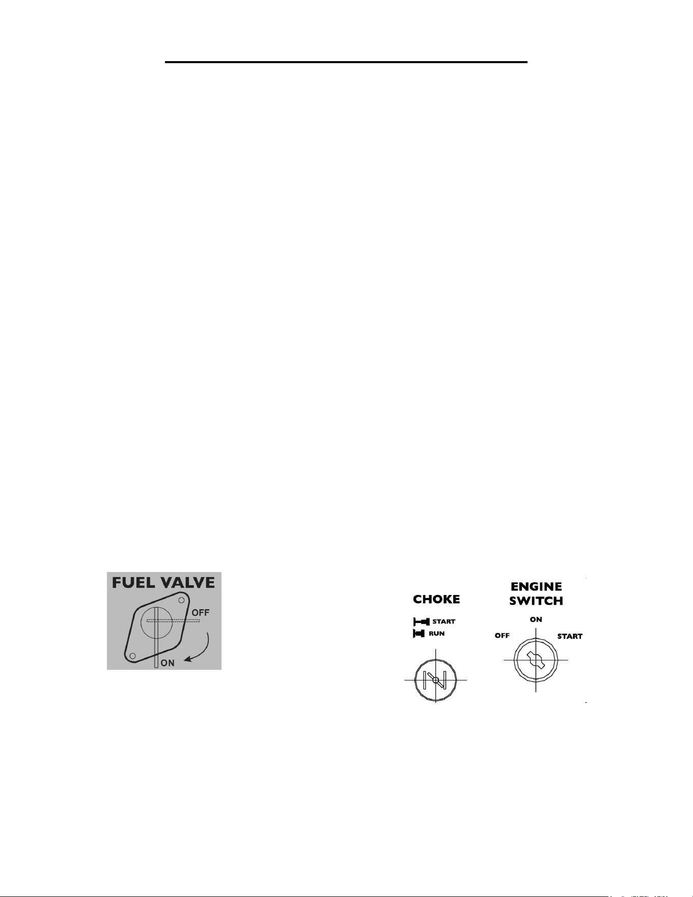
4. Turn the fuel valve to the “ON” position (Figure 4).
5. Pull the choke rod to the “Start” position.
6. Set the engine switch to the “ON” position.
7. Turn the engine switch to the “START” position for 2-3 seconds or until the engine starts. NOTE: If the en-
gine does not start after 2-3 seconds, release the switch from the start position. Keeping the switch in the START
position too long can damage the starter.
8. If engine fails to start, wait 10 seconds, then repeat step 7. NOTE: After repeated attempts to start the engine,
please consult the troubleshooting guide before attempting again. If problems persist please call (800) 232-1195
M-F 8-5 CST.
9. Once the engine has started. Slowly move the choke lever all the way to the “Run” position.
Allow the generator to run for several minutes before attempting to connect any electrical devices. This allows
the generator to stabilize its speed and temperature.
STARTING THE GENERATOR
Figure 4 - Fuel Valve
15
STOPPING THE GENERATOR
If this is not the first time using the generator, the user should take the following steps to prepare it for operation.
IMPORTANT: At this point the user should be familiar with the procedures described in
the sections titled “Starting the Generator” and “Generator Preparation.” If the user
has not yet read these sections, go back and read them now.
Step 1 - CHECK THE OIL
Oil consumption is normal during generator use. The generator is equipped with a low oil level shutoff to protect
it from damage. The oil level of the engine should be checked before each use to ensure that the engine crankcase
contains sufficient lubricant.
To check or add oil, follow these steps:
1. Make sure the generator is on a level surface. Clean around oil fill.
2. Remove the oil filler/dipstick cap and check the oil level.
3. If oil level is below the second thread from the lip of the oil fill opening, slowly add oil until the engine crank-
case is filled. Do not tilt the generator when adding oil.
4. Reinstall and tighten oil cap before starting the engine.
Step 2 - CHECK THE FUEL LEVEL
Before starting the generator, check to see that there is sufficient gasoline in the fuel tank. Add additional gasoline
as necessary but leave sufficient room in the tank for expansion.
SUBSEQUENT STARTING OF THE GENERATOR
TO STOP THE GENERATOR
1. Turn off all electrical devices prior to unplugging them from the generator. Unplugging running devices can
cause damage to the generator.
2. Turn the “ON/OFF” switch to the “OFF” position.
3. Turn the fuel valve to the “OFF” (horizontal) position.
WARNING: Allow the generator to cool for several minutes before touching areas that become hot dur-
ing use.
CAUTION: Allowing gasoline to sit in the fuel tank for long periods of time can make it difficult to start the
generator in the future. Never store the generator for extended periods of time with fuel in the fuel tank. Refer to
Generator Storage Section.

16
SUBSEQUENT STARTING OF THE GENERATOR
WARNING: This generator may emit highly flammable and explosive gasoline vapors, which can cause
severe burns or even death if ignited. A nearby open flame can lead to an explosion even if it is not
directly in contact with fuel.
• Do not operate near open flames.
• Do not smoke near the generator.
• Always operate on a firm, level surface.
• Always turn the generator off before refueling. Allow generator to cool for at least 2 minutes before re-
moving the fuel cap. Loosen cap slowly to relieve pressure in tank.
• Do not overfill fuel tank. Gasoline may expand during operation. Do not fill to the top of the tank. Allow
for expansion.
• Always check for spilled fuel before operating. Clean up any spilled fuel before starting.
• Empty the fuel tank before storing or transporting the generator.
• Before transporting, turn fuel valve to off position.
IMPORTANT:
• Use only UNLEADED gasoline.
• Do not use old gasoline.
• Never use an oil/gasoline mixture.
• Avoid getting dirt or water into the fuel tank.
Step 3 - GROUND THE GENERATOR
WARNING: Failure to properly ground the generator can result in electrocution.
Ground the generator by tightening the grounding nut on the front control panel against a grounding wire (Figure
3). A generally acceptable grounding wire is a No. 12 AWG (American Wire Gauge) stranded copper wire. This
grounding wire should be connected at the other end to a copper, brass, or steel-grounding rod that is driven into
the earth. Wire and grounding rod are not included in generator contents.
Grounding codes can vary by location. Contact a local electrician for area codes.

17
USING THE GENERATOR
WARNING: When this generator is used on a building’s wiring system, the generator must be installed by a qual-
ified electrician and connected to a transfer switch as a separately derived system in accordance with the National
Electrical Code, NFPA 70. The generator shall be connected to a transfer switch that switches all conductors
other than the equipment grounding conductor. The frame of the generator shall be connected to an approved
grounding electrode.
For power outages, permanently installed stationary generators are better suited for providing backup power to the
home. Even a properly connected portable generator can become overloaded. This may result in overheating or
stressing the machine’s components, possibly leading to a generator failure.
Before connecting electrical devices, allow the generator to run for a few minutes to stabilize the speed and voltage
output.
CAUTION: Become familiar with the markings on the panel before connecting electrical devices.
AC USAGE
Connect electrical devices running on AC current according to their wattage requirements. The chart in Figure 6
shows the rated and surge wattage of the generator.
The rated (running) wattage is the wattage the generator can produce on a continuous basis.
The surge wattage is the maximum amount of power the generator can produce for an extremely short period of
time (seconds). Many electrical devices such as refrigerators require short bursts of extra power in addition to the
rated wattage listed by the device to start their motors. The surge wattage ability of the generator covers this extra
power requirement.
Item Rated (Running) Wattage Surge Wattage
5613K 11000 13000
Figure 6 - Generator Wattage
The total running wattage requirement of the electrical devices connected to the generator should not exceed the
rated wattage of the generator itself. To calculate the total wattage requirement of the electrical devices you plan
to connect, find the rated (or running) wattage of each device. This number should be listed somewhere on the
device or in its instruction manual. If this wattage cannot be found, calculate it by multiplying the Voltage require-
ment by the Amperage drawn:
Watts = Volts x Amperes
If these specifications are not available, estimate the watts requirement of the device by using the chart in Figure 7.
When the rated wattage requirement of each electrical device has been determined, add these numbers to find
the total rated wattage needed. If this number exceeds the rated wattage of the generator, DO NOT connect all
these devices. Select a combination of electrical devices, which have a total rated wattage lower than or equal to
the rated wattage of the generator.

18
USING THE GENERATOR
CAUTION: The generator can run at its surge wattage capacity for only a short time. Connect electrical devices
requiring a rated (running) wattage equal to or less than the rated wattage of the generator. Never connect devices
requiring a rated wattage equal to the surge wattage of the generator. This can trip the circuit protectors (circuit
breakers).
Tool or Appliance Rated (Running) Watts ADDITIONAL SURGE WATTS
Electric water heater (40 Gal) 4000 0
Hot plate 2500 0
Saw - radial arm 2000 2000
Electric stove (each element) 1500-2800 0
Saw - circular 1500 1500
Air compressor (1 HP) 1500 3000
Window air conditioner 1200 1800
Saw - miter 1200 1200
Microwave 1000 0
Well water pump 1000 1000
Saw - reciprocating 960 1040
Sump pump 800 1200
Refrigerator freezer 800 1200
Furnace blower 800 1300
Computer 800 0
Electric drill 600 900
Television 500 0
Deep freezer 500 500
Garage door opener 480 0
Stereo 400 0
Box fan 300 600
Clock radio 300 0
Security system 180 0
DVD player / VCR 100 0
Common light bulb 75 0
Note: The above wattage figures are estimates. Check the wattage listed on the electrical device before consulting
this chart. Once the electrical devices that will be powered by the generator have been determined, plug in each
electrical device, making sure that the device is turned off.
CAUTION: Do not connect 50Hz loads to the generator.
Figure 7- Estimated wattage requirements of common electrical devices
19
USING THE GENERATOR
SOME NOTES ABOUT POWER CORDS
Long or thin cords can drain the power provided to an electrical device by the generator. When using such cords,
allow for a slightly higher rated wattage requirement by the electrical device. See Figure 8 for recommended
cords based on the power requirement of the electrical device.
Device Requirements
Max. Cord Length (ft) by Wire Gauge
Amps Watts (120V) #8 wire #10 wire #12 wire #14 wire #16 wire
2.5 300 NR NR NR 375 250
5 600 NR NR 300 200 125
7.5 900 NR 350 200 125 100
10 1200 NR 250 150 100 50
15 1800 NR 150 100 65 NR
*NR = Not Recommended Figure 8 - Maximum Extension Cord Lengths by Power Requirement
If an overload occurs, shut down the generator. Unplug all electrical devices and wait five minutes. Then, start the
unit back up again to get power back.
DC USAGE
This Generator is equipped with a 12V DC receptacle. The maximum draw for this DC outlet is 8.3 Amps. The
12V DC receptacle is not intended to charge automotive batteries.
HOUR METER

20
Proper routine maintenance of the generator will help prolong the life of the machine. Please perform mainte-
nance checks and operations according to the schedule in Figure 9.
If there are any questions about the maintenance procedures listed in this manual, please call (800) 232-1195 M-F
8-5CST.
CAUTION: Never perform maintenance operations while the generator is running.
Recommended
Maintenance Schedule
Each 8
hours or
daily
First 8
hours
Every 25
hours
Every 3
months or
50 hours
Every 6
months or
100 hours
Every
200
Hours
Every
year
As
necessary
Engine oil Check
level
x
Replace x x* x* x
Air
cleaner
cartridge
Check x x
Clean x
Spark plug Check/
clean
x
Change x x
Fuel tank Check
level
x
Clean x
Oil Filter Replace x
Figure 9 - Recommended maintenance schedule
* Clean/change more often under dusty conditions or operating under heavy load.
CLEANING THE GENERATOR
Never clean the generator when it is running! Never clean with a bucket of water or a hose. Water can get inside
the working parts of the generator and cause a short circuit or corrosion.
Always try to use the generator in a cool, dry place. If the generator becomes dirty, clean the exterior with a damp
cloth, a soft brush, a vacuum or compressed air.
CHECKING THE OIL
Check the oil level of the generator according to the Recommended Maintenance Schedule in Figure 9. The
generator is equipped with an automatic shutoff to protect it from running on low oil. The generator should be
checked before each use for proper oil level. This is a critical step for proper engine starting. To check the oil
level:
1. Make sure the generator is on a level surface.
2. Clean around oil fill. Remove dipstick and wipe the dipstick with a clean
rag. Insert the dipstick into the oil fill opening without screwing in. Remove
the dipstick to check the oil mark. Add oil if the oil mark covers less than one
half of the dipstick.
3. Slowly add more oil and repeat step 2 until the oil mark reaches to the top
of dipstick (Figure 10). Do not over fill the crankcase.
4. Reinstall oil dipstick.
MAINTENANCE & CARE
Figure 10 - Oil Fill Opening,
Dipstick and Oil Level
21
MAINTENANCE & CARE
To rell the crankcase with oil, follow these steps:
1. Make sure the generator is on a level surface. Tilting the generator
to assist in filling will cause oil to flow into engine areas and will cause
damage. Keep generator level!
2. Remove the dipstick from the engine.
3. Using a funnel or appropriate dispenser, add the correct amount of oil (50.7 fl.oz) into the crankcase. The
engine is equipped with a low oil sensor and will not start if the amount of oil is insufficient.
4. Reinstall dipstick.
NOTE: Never dispose of used motor oil in the trash or down a drain. Please
call a local recycling center or auto garage to arrange oil disposal.
AIR CLEANER MAINTENANCE
Routine maintenance of the air cleaner helps maintain proper airflow to the
carburetor. Running the engine with dirty, damaged or missing air cleaner
element will cause the engine to wear out prematurely. Occasionally check that
the air cleaner is free of excessive dirt. Refer to Recommended Maintenance
Schedule in Figure 9. For air cleaner detail, refer to Figure 11.
1. Turn fuel valve off, disconnect the fuel line of the fuel valve, then remove the fuel tank.
2. Open the air cleaner clip and open the air cleaner cover.
Figure 11 - Air Cleaner
3. Check and clean the air cleaner element, replace with a new one if the element is damaged. A good element
can be washed in soapy water, dried and reused. There is no need to add oil to the element.
4. Wipe off excessive oil from the air cleaner case. A small amount of oil in the element is normal and necessary
for the engine to work properly.
5. Reinstall the air cleaner element and cover.
CHANGING/ADDING OIL
Change the oil according to the Recommended Maintenance Schedule in Figure 9. Change the oil when the en-
gine is warm. This will allow for complete drainage. Change oil more often if operating under heavy load or high
ambient temperatures. It is also necessary to drain the oil from the crankcase if it has become contaminated with
water or dirt. The oil capacity of the generator engine is 50.7 fl.oz. Add oil when the oil level is low. For proper
type and weight of oil refer to “add oil” portion of the “Generator Preparation” section.
To drain oil, follow these steps:
1. Place a container underneath the engine to catch oil as it drains.
2. Using a 10 mm hex wrench, unscrew the oil drain plug. Allow all
the oil to drain from the engine.
3. Reinstall the oil drain plug and tighten with a 10 mm hex wrench.
Drain Plug
22
MAINTENANCE & CARE
SPARK PLUG MAINTENANCE
Spark plug: Torch F5RTC
The spark plug is important for proper engine operation. A good spark plug should be intact, free of deposits,
and properly gapped. Refer to Recommended Maintenance Schedule in Figure 9. To inspect the spark plug:
1. Remove spark plug boot. Be careful not to tear insulation or wire.
2. Unscrew the spark plug from the engine using the spark plug wrench provided. There is limited space for the
wrench to turn. Use both rows of holes in the spark plug wrench to gain leverage to loosen the plug.
3. Visually inspect the spark plug for cracks or excessive electrode wear. Replace as necessary.
4. Measure the plug gap with a wire gauge. The gap should be 0.7 to 0.8 mm (0.028-0.031 in).
5. If re-using the spark plug, use a wire brush to clean any dirt from around the spark plug base then re-gap the
spark plug.
6. Screw the spark plug back into the spark plug hole using the spark plug wrench. Do not over-tighten spark
plug. Recommended tightening of spark plug is ½ to ¾ of a turn after spark plug gasket contacts spark plug hole.
Reinstall the spark plug boot.
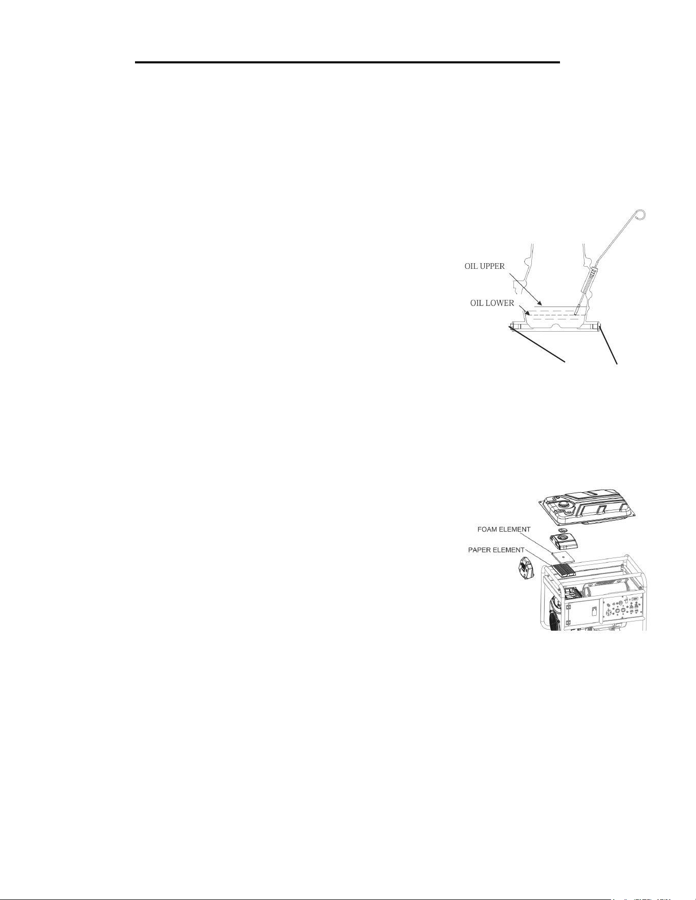
FUEL FILTER CUP CLEANING
The fuel filter cup is a small well underneath the fuel valve. It helps to trap dirt and water that may be in the fuel
tank before it can enter the engine. To clean the fuel filter cup:
1. Turn the fuel valve to the “OFF” position.
2. Unscrew the fuel filter cup from the fuel valve using a wrench. Turn the valve toward you
and unscrew (See Figure 12).
3. Clean the cup of all sediments using a rag or brush.
4. Reinstall the fuel filter cup.
Figure 12 Removing the Fuel Filter Cup
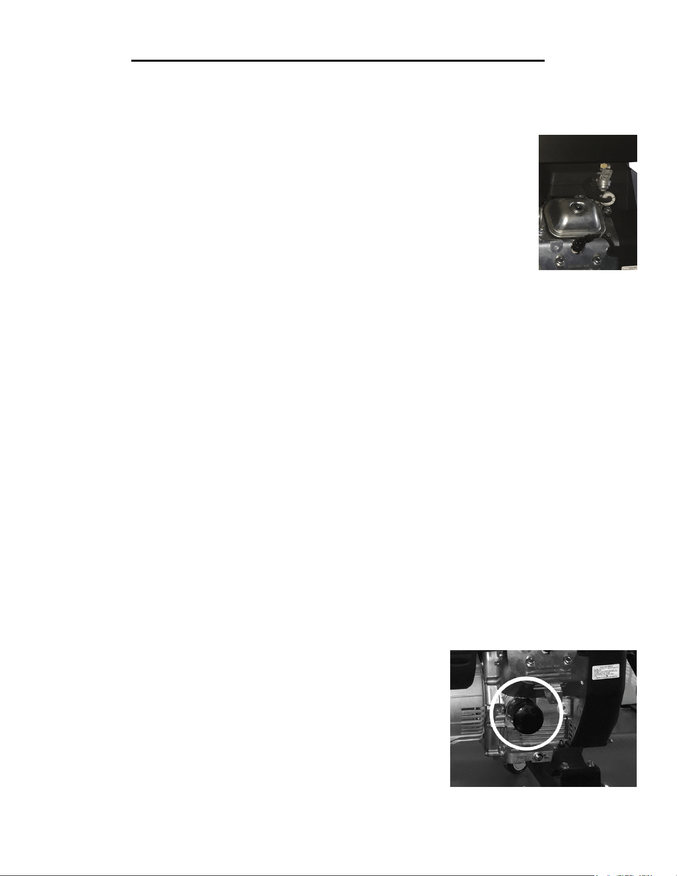
OIL FILTER MAINTENANCE
Every 200 hours of use, make sure to change out your oil filter. The oil
filter can be found on the back of the generator at the base of the engine, as
shown in figure 13.
Figure 13 Oil Filter Location

23
MAINTENANCE & CARE
STORAGE & TRANSPORT PROCEDURES
DRAINING THE FUEL TANK
Clean fuel tank each year or before storing the generator for extended periods of time. To drain the fuel tank and
carburetor:
1. Turn the fuel valve to the “OFF” position.
2. Remove the fuel line between the fuel valve and carburetor. CAUTION: A small amount of fuel may leak from
the hose during removal.
3. Attach a fuel line (not included with the generator) to the exposed end of the fuel valve.
4. Position fuel line into an appropriate container and open the fuel valve allowing fuel to flow into the container.
5. Once fuel is drained, shut off the fuel valve.
6. Start and run the engine until fuel runs out.
7. Remove the fuel filter cup (See “FUEL FILTER CUP CLEANING”).
8. Empty the fuel filter cup of any fuel and clean.
9. Reinstall the fuel filter cup.
10. Store the emptied gasoline in a suitable place.
CAUTION: Do not store fuel for more than 3 months.
CAUTION: Never place any type of storage cover on the generator while it is still hot.
IMPORTANT: If the generator is being stored for short periods of time (30 to 60 days), add stabilized fuel to the
fuel tank until full. NOTE: Filling the tank reduces the amount of air in the tank and helps reduce deterioration
of fuel. Run the engine for 10 minutes allowing stabilized fuel mixture to circulate through the carburetor.
When storing the generator for extended periods of time:
• Drain the fuel tank (see “Draining the Fuel Tank” in the “Maintenance” section).
• Change oil.
• Do not obstruct any ventilation openings.
• Keep the generator in a cool dry area.
When transporting generator:
• Tighten fuel cap and vacuum relief valve. Drain the fuel tank if possible (see “Draining the Fuel Tank” in the
“Maintenance” section).
• Keep the generator upright.

24
SPECIFICATIONS
DC output
Rated Voltage 12 V DC
Rated Amperage 8.3 A
Rated Wattage 100 W
AC output
Rated Wattage 11000 Watts
Surge Wattage 13000 Watts
Rated Voltage 120V / 240V
Rated Amperage 91.6A / 45.8A
Frequency 60 Hz
Phase Single
Dimensions
Length: 32.50 inches
Width: 23.625 inches
Height: 27 inches
Weight 330 lbs
Engine
Engine type 4 stroke, OHV, twin cylinder with forced air cooling system
Spark plug gap 0.7 - 0.8 mm (0.028 - 0.031 in)
Spark plug torque 1/2 - 3/4 turn after gasket contacts base or 15 ft.lb
Displacement 670 cc
Fuel tank capacity 8 gallons 87 octane minimum
Oil capacity 50.7 fl.oz
Lubrication system Oil Pump
Run time on 50% load 7.5 hours
Noise rating 82 dB at 22 feet
Spark plug Torch F5RTC

25
TROUBLESHOOTING
IMPORTANT: If trouble persists, please call our customer help line at (800) 232-1195 M-F 8-5 Central Time.
PROBLEM CAUSE SOLUTION
Engine will not start. Engine switch is set to OFF. Set engine switch to ON.
Fuel valve is turned to OFF. Turn fuel valve to ON position.
Choke is open. Close the choke.
Engine is out of gas. Add gas.
Engine is filled with contaminated
or old gas.
Change the gas in the tank.
Spark plug is dirty. Clean the spark plug.
Spark plug is broken. Replace spark plug.
Generator is not on a level surface. Move the generator to a level surface to pre-
vent low oil shutdown from triggering.
Oil is low. Add or replace oil.
Engine runs but there is
no electrical output.
Circuit reset button is off. Wait for two minutes and push the circuit
reset button to the ON position.
Bad connecting wires/cables. If you are using an extension cord, use a dif-
ferent one.
Bad carbon brushes (5613K-1613) Have the carbon brushes replaced by an expe-
rienced service technician.
Bad electrical device connected to
the generator.
Try connecting a different device.
Generator runs but does
not support all electrical
devices connected.
Generator is overloaded. Perform these steps:
1. Turn off all electrical devices.
2. Unplug all electrical devices.
3. Turn off generator.
4. Wait several minutes.
5. Restart generator.
6. Try connecting few electrical loads to the
generator.
Short in one of the devices. Try disconnecting any faulty or short-circuited
electrical loads.
Air cleaner is dirty. Clean or replace air cleaner.
DC No Power Power cord plug not securely in
place.
Twist and push the power cord plug into re-
ceptacle until contact is made with bottom of
the receptacle.
Protective fuse is blown. Contact our customer service help line at
800-232-1195.
26
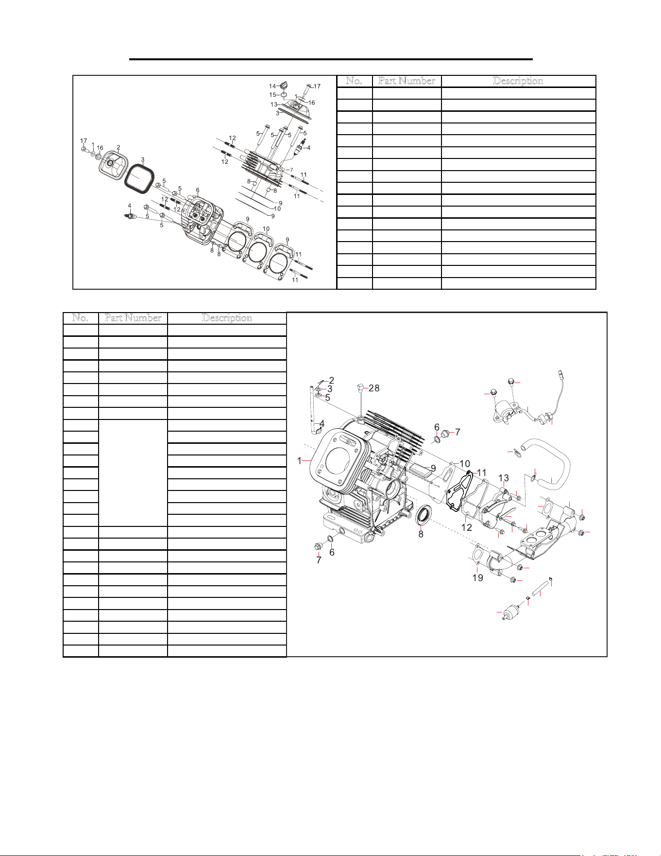
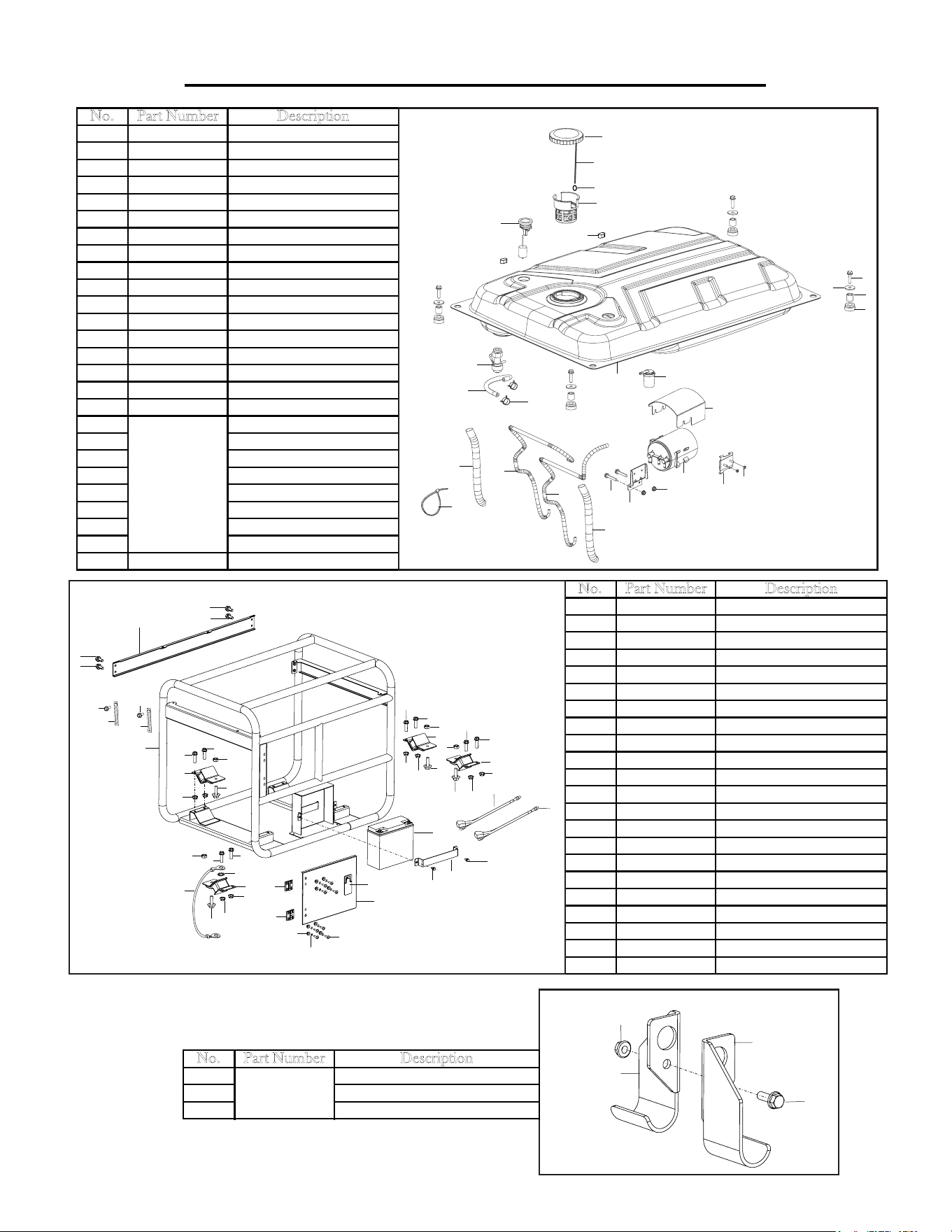
EXPLODED VIEW AND PARTS LIST
No. Part Number Description
1-1 5613K-0101 Cylinder Head Cover Washer
1-2 5613K-0102 Cylinder Head Cover
1-3 5613K-0103 Head Cover Gasket
1-4 5613K-0104 Spark Plug
1-5 5613K-0105 Cylinder Head Bolt
1-6 5613K-0106 Left Cylinder Head
1-7 5613K-0107 Right Cylinder Head
1-8 5613K-0108 Bushing
1-9 5613K-0109 Head Gasket
1-10 5613K-0110 Middle Gasket
1-11 5613K-0111 Right Studs
1-12 5613K-0112 Left Stud
1-13 5613K-0113 Right Cylinder Head Cover
1-14 5613K-0114 Engine Oil Plug
1-15 5613K-0115 Oil Seal
1-16 5613K-0116 Cylinder Head Washer
1-17 5613K-0117 Cylinder Head Bolt
Fig. 1 - Cylinder Head Assembly
26
26
25
27
17
17
18
15
14
15
16
16
19
20
21
21
21
21
23
24
23
22
No. Part Number Description
2-1 5613K-0201 Crankcase Assembly
2-2 5613K-0202 Cotter Pin
2-3 5613K-0203 Flat Washer
2-4 5613K-0204 Governor
2-5 5613K-0205 Washer
2-6 5613K-0206 Oil Seal Washer
2-7 5613K-0207 Oil Drain Plug
2-8 5613K-0208 Oil Seal
2-9 Breather Filter
2-10 Breather Backing Plate
2-11 Breather Back Gasket
2-12 Breather Front Gasket
2-13 Breather Cover
2-14 Clamp
2-15 Bolt
2-16 Bolt
2-17 Clamp
2-18 5613K-0218 Breather Tube
2-19 5613K-0219 Intake Gasket
2-20 5613K-0220 Intake
2-21 5613K-0221 Nut
2-22 5613K-0222 Fuel Filter
2-23 5613K-0223 Hose Clamp
2-24 5613K-0224 Fuel Hose
2-25 5613K-0225 Oil Sensor
2-26 5613K-0226 Bolt
2-27 5613K-0227 Nut
2-28 5613K-0228 Block
5613K-0200
Breather
Assembly
Fig. 2 - Crankcase
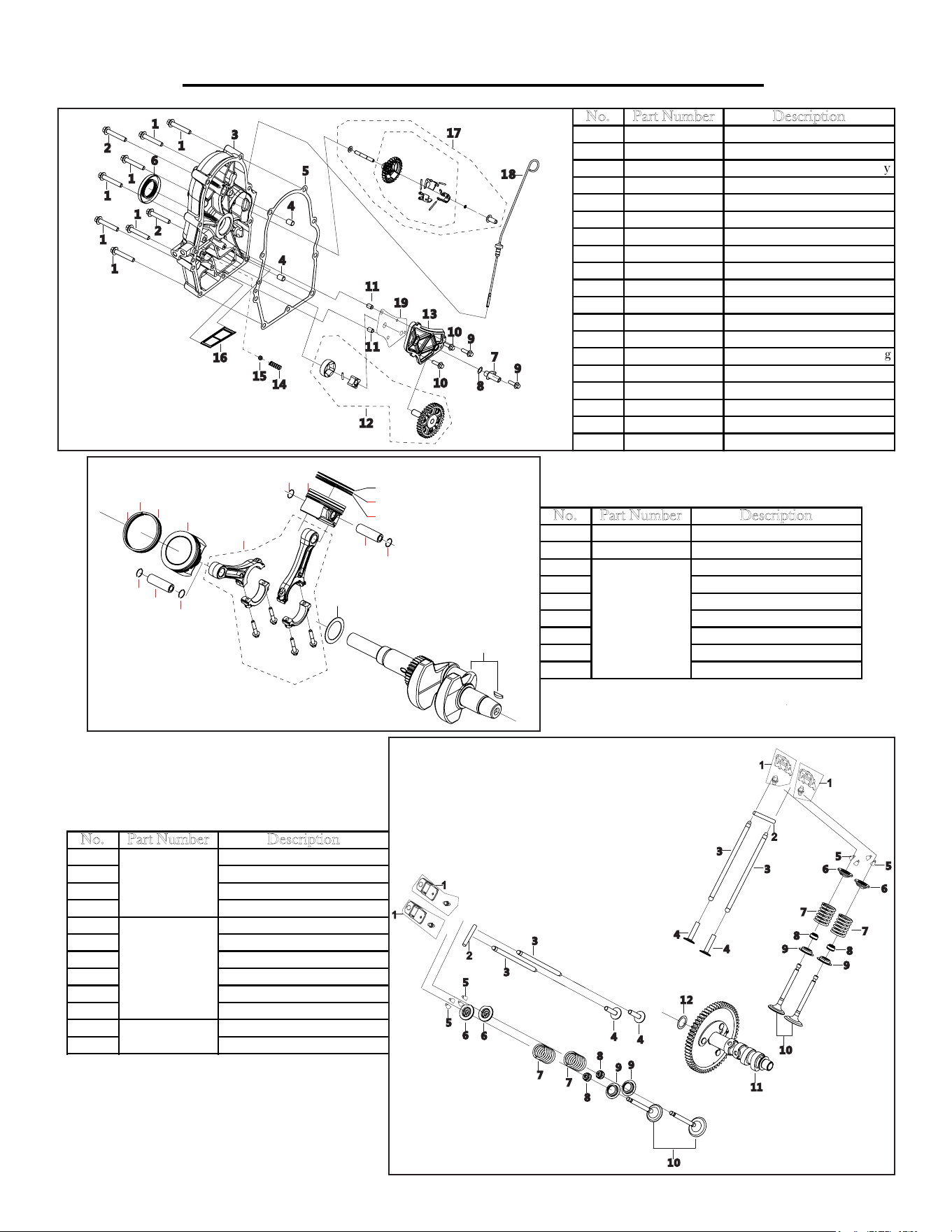
27
EXPLODED VIEW AND PARTS LIST
No. Part Number Description
3-1 5613K-0301 Bolt
3-2 5613K-0302 Bolt
3-3 5613K-0303
Crankcase Cover Assembly
3-4 5613K-0304 Pin
3-5 5613K-0305 Crankcase Gasket
3-6 5613K-0306 Oil Seal
3-7 5613K-0307 Oil Suction Hose
3-8 5613K-0308 Washer
3-9 5613K-0309 Bolt
3-10 5613K-0310 Bolt
3-11 5613K-0311 Pin
3-12 5613K-0312 Oil Pump
3-13 5613K-0313 Oil Pump Cover
3-14 5613K-0314
Pressure Relief Valve Spring
3-15 5613K-0315 Steel Ball
3-16 5613K-0316 Oil Filter
3-17 5613K-0317 Governor Gear Assembly
3-18 5613K-0318 Oil Dipstick Assembly
3-19 5613K-0319 Oil Pump Gasket
Fig. 3 - Crankcase Cover
No. Part Number Description
4-1 5613K-0401 Crankshaft Assembly
4-3 5613K-0403 Thrust Washer
4-4 Connecting Rod
4-5 Piston
4-6 Piston Pin
4-7 Piston Clip
4-8 Top Piston Ring
4-9 Bottom Piston Ring
4-10 Piston Oil Seal
5613K-0400
Connecting
Rod Assembly
No. Part Number Description
5-1 Valve Rocker
5-2 Valve Rocker Shaft
5-3 Valve Lifter
5-4 Valve Tappet
5-5 Valve Clamp
5-6 Valve Spring Seat
5-7 Valve Spring Seat
5-8 Seal Guide
5-9 Valve Spring Retainer
5-10 Valve
5-11 Camshaft Assembly
5-12 Camshaft Washer
5613K-0500
Valve Rocker
Assembly
5613K-0515
Valve
Assembly
5613K-0520
Camshaft
1
3
4
5
6
7
8
9
10
7
8
9
10
5
7
7
6
Fig. 4 - Crankshaft and Connecting Rod
Fig. 5 - Valve Train &
Camshaft Assembly
28
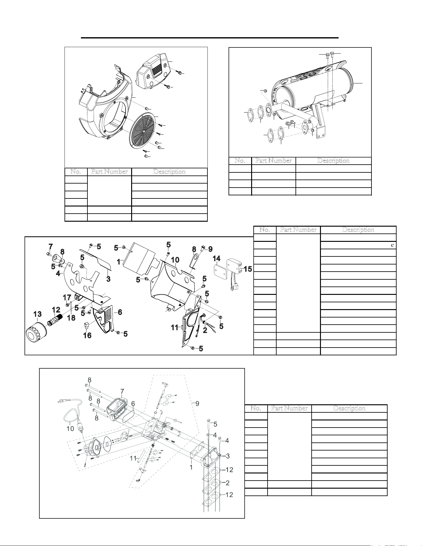
EXPLODED VIEW AND PARTS LIST
No. Part Number Description
6-1 Shroud Shield
6-2 Screw
6-3 Nut
6-4 Shroud Assembly
6-5 5613K-0605 Fan Shield
6-6 5613K-0606 Lock Handle
5613K-0600
Outer Shroud
Assembly
No. Part Number Description
7-1 Cylinder Body Shroud 2
7-2
Ignition Coil Shutoff Wire
7-3 Cyldiner Body Shroud 1
7-4 Left Shield Underside
7-5 Bolt
7-6 Left Crankcase Shield
7-7 Flange Bolt
7-8 Lug
7-9 Flange Bolt
7-10 Right Shield Underside
7-11 Right Crankcase Shield
7-12 Oil Filter Tube
7-13 Extra Oil Filter
7-14 5613k-0714 Regulator Board
7-15 5613k-0715 Voltage Regulator
7-16 5613k-0716 Block
5613K-0700
Shroud
Assembly
No. Part Number Description
8-1 Carburetor Seal Gasket
8-2 Carburetor Gasket
8-3 Carburtor Intake Joint
8-4 Bolt
8-5 Bolt
8-6 Seal
8-7 Air Cleaner Connection
8-8 Bolt
8-9 Carburetor Assembly
8-11 5613K-0811 Solenoid Valve
8-12 5613K-0812 Fuel Line
5613K-0800
Carburetor
Assembly
1
2
2
2
3
3
3
3
4
5
6
6
Fig. 6 - Outer Housing
17
18
Fig. 7 - Cylinder Body Shroud/Lower Shield
Fig. 8 - Carburetor Assembly
No. Part Number Description
12-1 5613K-1201 Muffler Assembly
12-2 5613K-1202 Exhaust Outlet Gasket
12-3 5613K-1203 Bolt
12-4 5613K-1204 Nut
1
2
2
4
4
2
2
3
3
4
4
3
3
Fig. 12 - Muffler
EXPLODED VIEW AND PARTS LIST
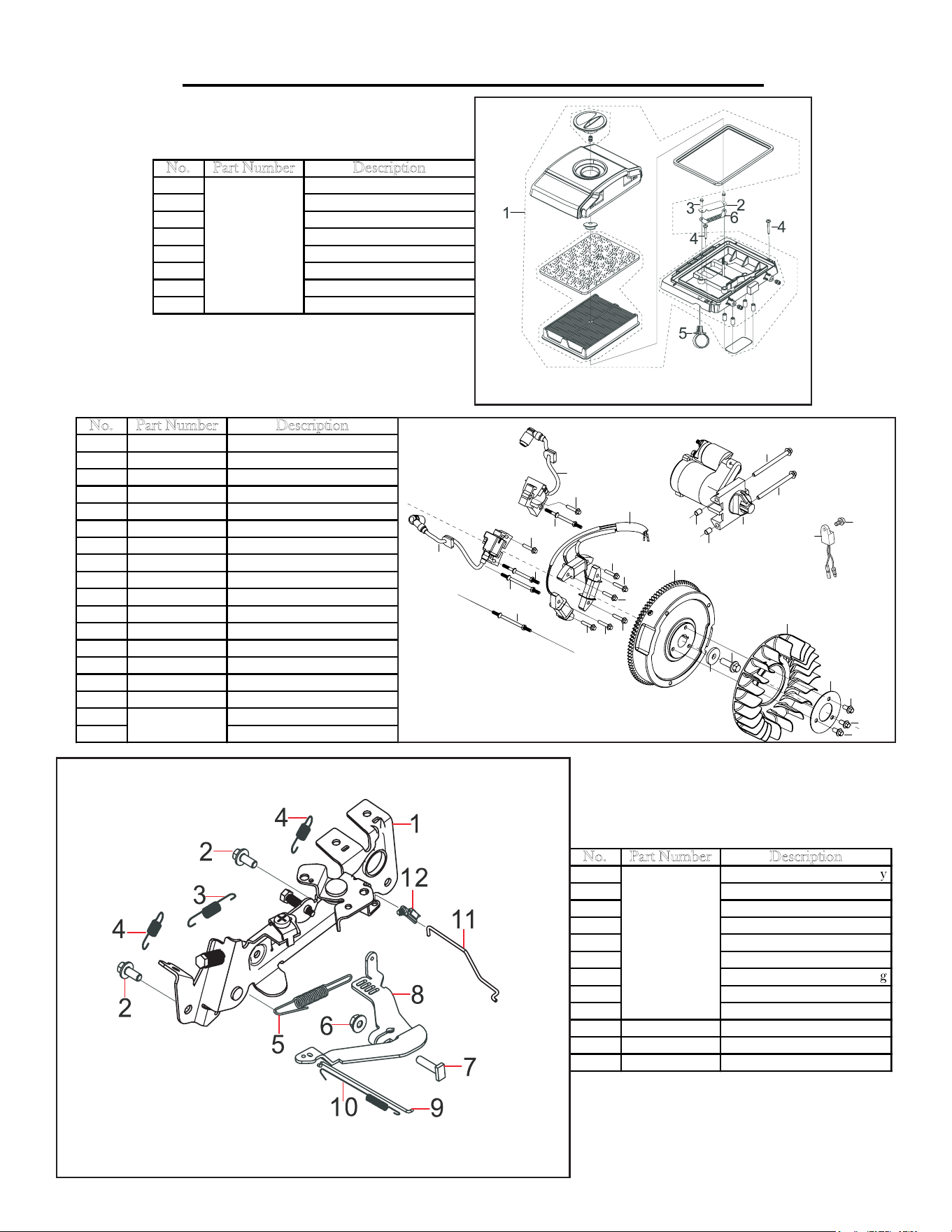
29
No. Part Number Description
9-1 Air Cleaner
9-2 Intake Tube Cover
9-3 Bolt
9-4 Screw
9-5 Clamp
9-6 Intake Tube Cover
9-7 Fuel Vapor Hose
9-8 Hose Clamp
5613K-0900
Air Cleaner
Fig. 9 - Outer Housing
No. Part Number Description
10-1 5613K-1001 Left Ignition Coil
10-2 5613K-1002 Right Ignition Coli
10-3 5613K-1003 Bolt
10-4 5613K-1004 Stud
10-5 5613K-1005 Stud
10-6 5613K-1006 Charge Coil Assembly
10-7 5613K-1007 Bolt
10-8 5613K-1008 Flywheel Assembly
10-9 5613K-1009 Washer
10-10 5613K-1010 Flywheel Bolt
10-11 5613K-1011 Impeller
10-12 5613K-1012 Impeller Setting Plate
10-13 5613K-1013 Bolt
10-14 5613K-1014 Pin
10-15 5613K-1015 Starter Assembly
10-16 5613K-1016 Bolt
10-17 Oil Protector
10-18 Bolt
5613K-1020
Oil Protector
1
2
3
3
4
4
5
5
6
7
7
7
7
7
7
8
9
10
11
12
13
13
13
14
14
15
16
16
17
18
Fig. 10 - Flywheel/Starter Pulley
Ignition Coil/Impeller
No. Part Number Description
11-1
Throttle Control Assembly
11-2 Bolt
11-6 Nut
11-7 Governor Support Bolt
11-8
Governor Support Assembly
11-9 Governor Rod
11-10 Throttle Returning Spring
11-11 Choke Rod
11-12 Choke Rod Clip
11-3 5613K-1103 Governor Return Spring
11-4 5613K-1104 Choke Return Spring
11-5 5613K-1105 Governor Spring
5613K-1101
Throttle
Assembly
Fig. 11 - Throttle Control
Assembly
EXPLODED VIEW AND PARTS LIST
29
No. Part Number Description
9-1 Air Cleaner
9-2 Intake Tube Cover
9-3 Bolt
9-4 Screw
9-5 Clamp
9-6 Intake Tube Cover
9-7 Fuel Vapor Hose
9-8 Hose Clamp
5613K-0900
Air Cleaner
Fig. 9 - Outer Housing
No. Part Number Description
10-1 5613K-1001 Left Ignition Coil
10-2 5613K-1002 Right Ignition Coli
10-3 5613K-1003 Bolt
10-4 5613K-1004 Stud
10-5 5613K-1005 Stud
10-6 5613K-1006 Charge Coil Assembly
10-7 5613K-1007 Bolt
10-8 5613K-1008 Flywheel Assembly
10-9 5613K-1009 Washer
10-10 5613K-1010 Flywheel Bolt
10-11 5613K-1011 Impeller
10-12 5613K-1012 Impeller Setting Plate
10-13 5613K-1013 Bolt
10-14 5613K-1014 Pin
10-15 5613K-1015 Starter Assembly
10-16 5613K-1016 Bolt
10-17 Oil Protector
10-18 Bolt
5613K-1020
Oil Protector
1
2
3
3
4
4
5
5
6
7
7
7
7
7
7
8
9
10
11
12
13
13
13
14
14
15
16
16
17
18
Fig. 10 - Flywheel/Starter Pulley
Ignition Coil/Impeller
No. Part Number Description
11-1
Throttle Control Assembly
11-2 Bolt
11-6 Nut
11-7 Governor Support Bolt
11-8
Governor Support Assembly
11-9 Governor Rod
11-10 Throttle Returning Spring
11-11 Choke Rod
11-12 Choke Rod Clip
11-3 5613K-1103 Governor Return Spring
11-4 5613K-1104 Choke Return Spring
11-5 5613K-1105 Governor Spring
5613K-1101
Throttle
Assembly
Fig. 11 - Throttle Control
Assembly
30
EXPLODED VIEW AND PARTS LIST
No. Part Number Description
13-1
5613K-1301 Fuel Tank
13-2
5613K-1302 Fuel Tank Support
13-3
5613K-1303 Sleeve
13-4
5613K-1304 Washer
13-5
5613K-1305 Bolt
13-6
5613K-1306 Fuel Cap
13-7
5613K-1307 Fuel Gauge
13-8
5613K-1308 Fuel Filter
13-9
5613K-1309 Fuel Cock
13-10
5613K-1310 Fuel Hose
13-11
5613K-1311 Clamp
13-12
5613K-1312 One-way Valve
13-13
5613K-1313 Fuel Tank Cushion
13-15
5613K-1315 Fuel Cap Chain
13-16
5613K-1316 Chain Lock Clip
13-17
5613K-1317 Fuel Vapor Tube
13-18
5613K-1318 Air Cleaner Tube
13-19
Collection Plate
13-20
Bolt
13-21
Nut
13-22
Collector Cover
13-23
Bolt
13-24
Support
13-25
Nut
13-26
Collector
13-27
5613K-1327 Bellows
5613K-1300
Collector
Assembly
1
2
3
5
6
7
8
9
10
4
12
11
13
15
16
19
20
21
22
26
27
18
17
24
25
23
27
Fig. 13 - Fuel Tank
No. Part Number Description
14-1 5613K-1401 Frame
14-2 5613K-1402 Rear Plate
14-3 5613K-1403 Bolt
14-4 5613K-1404 Bolt
14-5 5613K-1405 Nut
14-6 5613K-1406 Frame Cushion
14-7 5613K-1407 Hinge
14-8 5613K-1408 Oil Panel Plate
14-9 5613K-1409 Screw
14-10 5613K-1410 Lock
14-11 5613K-1411 Bolt
14-12 5613K-1412 Battery Pressure Plate
14-13 5613K-1413 Battery
14-14 5613K-1414 Postive Wire
14-15 5613K-1415 Negative Wire
14-16 5613K-1416 Bolt
14-17 5613K-1417 Bolt
14-18 5613K-1418 Nut
14-19 5613K-1419 Lock Washer
14-20 5613K-1420 Ground Wire
14-21 5613K-1421 Spring Washer
14-22 5613K-1422 Nut
1
2
3
4
5
6
12
11
13
7
8
9
10
15
14
16
17
3
3
3
4
4
4
5
4
4
5
4
4
5
6
6
6
7
17
11
16
18
18
18
18
18
18
18
19
20
21
22
23
24
1
1
2
3
24
23
Fig. 14 - Frame
1
1
2
3
Fig. 18 - Hook
No. Part Number Description
18-1
Lifting Hook
18-2 Bolt
18-3 Nut
5613K-1800
31
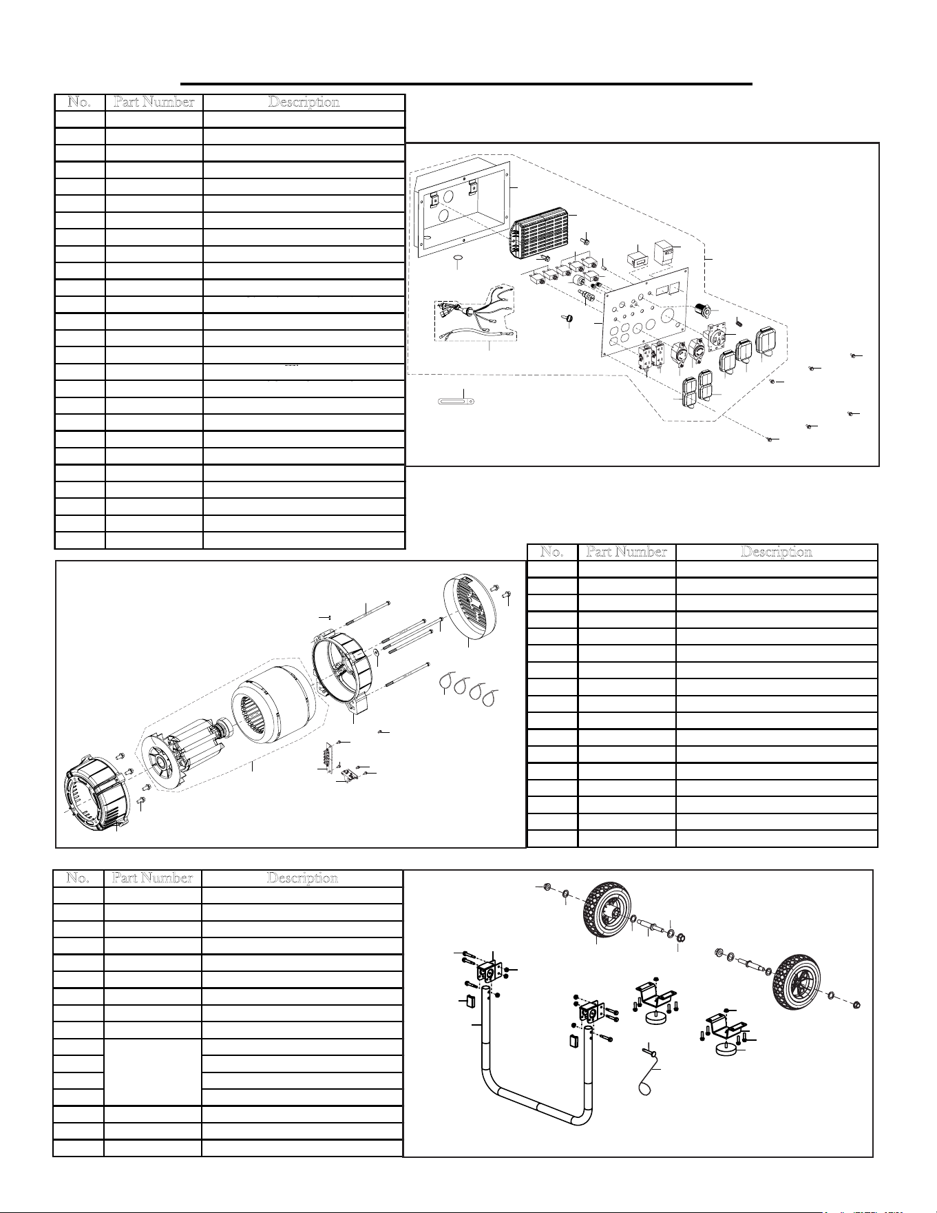
EXPLODED VIEW AND PARTS LIST
No. Part Number Description
15-1 5613K-1501 Washer
15-2 5613K-1502 Bolt
15-3 5613K-1503 Ignition Key
15-4 5613K-1504 Control Panel Assembly
15-5 5613K-1505 Regulator
15-6 5613K-1506 Control Panel Face
15-7 5613K-1507 Control Panel Housing
15-8 5613K-1508 Bolt
15-9 5613K-1509 Choke Lock Assembly
15-10 5613K-1510 Switch Assembly
15-11 5613K-1511 Circuit Breaker 30A
15-12 5613K-1512 Circuit Breaker 50A
15-13 5613K-1513 DC Socket
15-14 5613K-1514 Oil Indicator
15-15 5613K-1515 Circuit Breaker 20 A
15-16 5613K-1516 Timer
15-17 5613K-1517 Double Pole Breaker
15-18 5613K-1518 Ground Terminal
15-19 5613K-1519 240V Socket Assembly
15-20 5613K-1520 Water Proof Cover 240 Socket
15-21 5613K-1521 120V/240V Socket
15-22 5613K-1522 Water Proof Cover 120 Socket
15-23 5613K-1523 120V 30A Socket
15-24 5613K-1524 120V Socket Duplex
15-25 5613K-1525 Water Proof Cover Duplex
15-26 5613K-1526 Clip
19
6
19
21
23
24
24
17
16
18
4
7
5
8
26
13
1
8
14
15
11
3
10
25
25
22
22
20
2
2
2
2
2
2
9
12
Fig. 15 - Control Panel Assembly
No. Part Number Description
16-1
5613K-1601 Motor Front Cover
16-2
5613K-1602 Bolt
16-3
5613K-1603 Rotor/Stator Assembly
5613K-1603-1 Stator
5613K-1603-2 Rotor
16-4
5613K-1604 Stator Support
16-5
5613K-1605 Washer
16-6
5613K-1606 Bolt
16-7
5613K-1607 Stator End Cap
16-8
5613K-1608 Rotor Bolt
16-9
5613K-1609 Bolt
16-10
5613K-1610 Screw
16-11
5613K-1611 Band
16-12
5613K-1612 Wire Connection
16-13
5613K-1613 Carbon Brush
16-14
5613K-1614 Bolt
16-15
5613K-1615 Bolt
1
2
3
4
6
5
7
8
9
10
11
12
13
14
15
15
14
15
Fig. 16 - Rotor/Stator
No. Part Number Description
17-1 5613K-1701 Handle
17-2 5613K-1702 Handle Support
17-3 5613K-1703 Bolt
17-4 5613K-1704 Lock Nut
17-5 5613K-1705 Handle Bracket
17-6 5613K-1706 Nut
17-7 5613K-1707 Frame Cushion Bracket
17-8 5613K-1708 Frame Cushion
17-9 5613K-1709 Wheel
17-10 Axle
17-11 Washer
17-12 Lock Nut
17-13 Washer
17-14 5613K-1714 Bolt
17-15 5613K-1715 Pin Shaft
17-16 5613K-1716 Wire Tie
5613K-1700
Axle
Assembly
3
4
5
1
8
6
7
2
12
13
10
12
9
14
15
16
11
11
Fig. 17 - Front Handle Wheel Assembly
Circuit Breaker 20A
Circuit Breaker 10A
46A Double Pole Breaker
Circuit Breaker 30A
Hour Meter
32
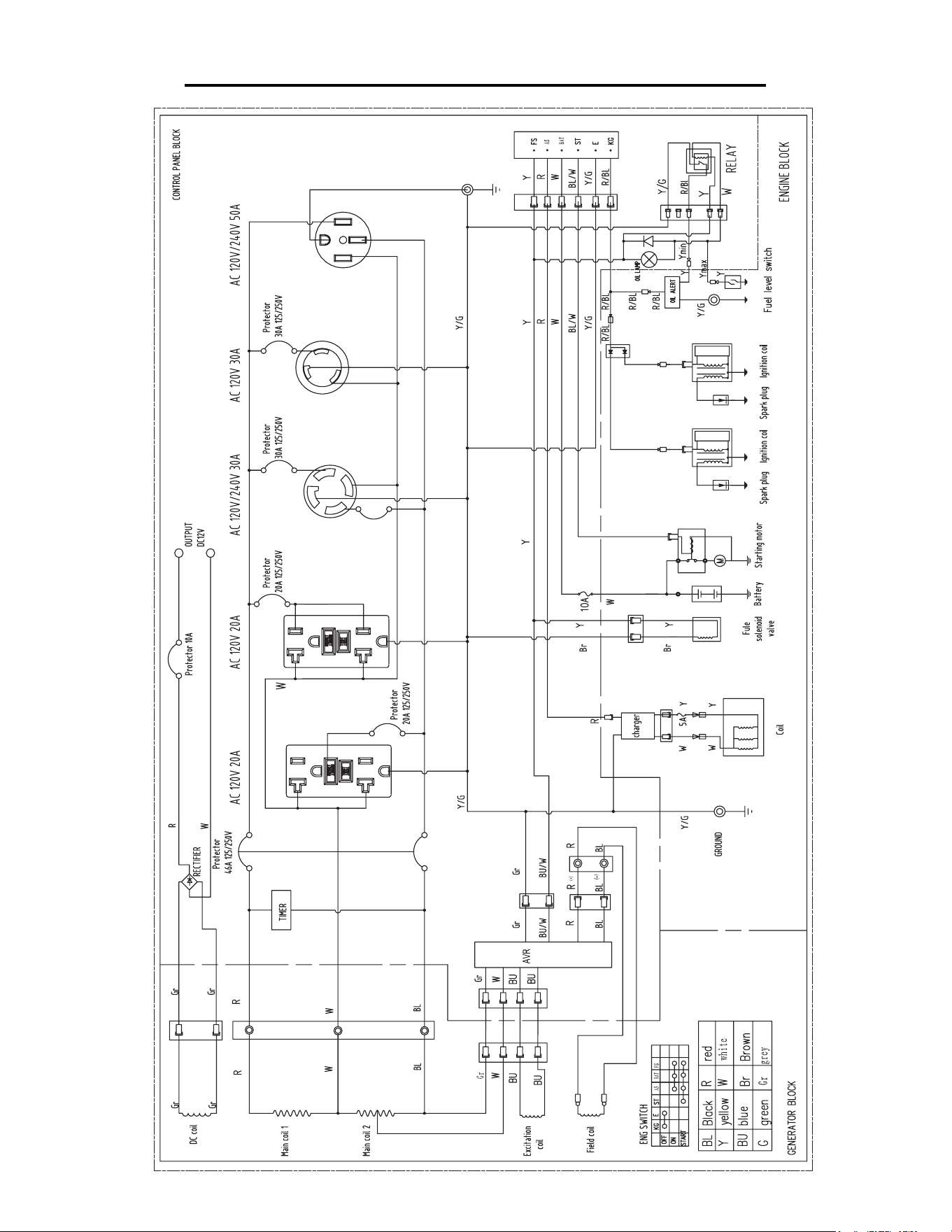
WIRING DIAGRAM
32

33
WARRANTY STATEMENT
Remember to save the receipt and to accurately fill out and mail the product registration card. Proof of purchase is
required for all warranty work.
WEN® generators are under warranty to be free from defects in materials and workmanship for a period of two
(2) years from date of original purchase. Generators used for Commercial or Rental use have a warranty period of
90 days from date of original purchase. Keep purchase receipt and mail in the product registration card for proof
of purchase.
WEN® will repair or replace, at its discretion, any part that is proven to be defective in materials or workmanship
under normal use during the two (2) years warranty period. Warranty repairs or replacements will be made without
charge for parts or labor. Parts replaced during warranty repairs will be considered as part of the original product
and will have the same warranty period as the original product.
To exercise the warranty, DO NOT RETURN TO RETAILER. Instead, call the toll free Customer Service num-
ber at (800) 232-1195 (Mon through Fri, 8 to 5 CST) and you will be instructed on where to take the generator for
warranty service. Take the generator and proof of purchase (the receipt) to the repair facility recommended by the
Customer Service Representative. Units that have been resold in some way and secondhand units are not covered
under warranty.
To make a claim under this Limited Warranty, you must make sure to keep a copy of your proof of purchase that
clearly defines the Date of Purchase (month and year) and the Place of Purchase. Place of purchase must be a direct
vendor of Great Lakes Technologies, LLC. Third party vendors such as garage sales, pawn shops, resale shops, or
any other secondhand merchant void the warranty included with this product. Contact techsupport@wenproducts.
com or 1-800-232-1195 to make arrangements for repairs and transportation.
When returning a product for warranty service, the shipping charges must be prepaid by the purchaser. The prod-
uct must be shipped in its original container (or an equivalent), properly packed to withstand the hazards of ship-
ment. The product must be fully insured with a copy of the warranty card and/or the proof of purchase enclosed.
There must also be a description of the problem in order to help our repairs department diagnose and fix the issue.
Repairs will be made and the product will be returned and shipped back to the purchaser at no charge.
THIS LIMITED WARRANTY DOES NOT APPLY TO ACCESSORY ITEMS THAT WEAR OUT FROM
REGULAR USAGE OVER TIME INCLUDING BELTS, BRUSHES, BLADES, ETC.
This warranty is conveyed to the original purchaser and is not transferable. Generators contain parts that will wear
out with usage and parts that need maintenance. The warranty does not cover wear or maintenance parts. Specifi-
cally, the warranty does not cover replacement of air filters, spark plugs, oil filters, fuel filters, brushes, or voltage
regulators. Battery is only covered for 90 days after purchase.
The warranty does not extend to generators damaged or affected by fuel contamination, accidents, neglect, misuse,
unauthorized alterations, use in an application for which the product was not designed and any other modifications
or abuse.
WEN® is not liable for any indirect, incidental or consequential damages from the sale or use of this product. Any
implied warranties are limited to two (2) years as stated in this written limited warranty. Some states do not allow the
exclusion or limitation of incidental or consequential damages. Some states do not allow limitation on the length of
an implied warranty. This warranty gives you specific legal rights, and you may have other rights that vary from state
to state.

Thanks for remembering
93004-Y4D0540-0000