
Model # 56230
30-TON GAS
LOG SPLITTER
bit.ly/WENvideo
Your new tool has been engineered and manufactured to WEN’s highest standards for dependability,
ease of operation, and operator safety. When properly cared for, this product will supply you years
of rugged, trouble-free performance. Pay close attention to the rules for safe operation, warnings,
and cautions. If you use your tool properly and for intended purpose, you will enjoy years of safe,
reliable service.
IMPORTANT:
NEED HELP? CONTACT US!
Have product questions? Need technical support?
Please feel free to contact us at:
800-232-1195
WENPRODUCTS.COM
(M-F 8AM-5PM CST)

SERVICE RECORD
Record Service Dates:
Date Date Date Date Date Date
Change Oil
Change Spark Plug
Clean Fuel Tank
Clean Air Cleaner
TABLE OF CONTENTS
2
LOG SPLITTER IDENTIFICATION
If assistance for information or service is required, please contact the Customer Service Help Line by calling
800-232-1195; customer will be asked to provide log splitter information when calling. Keep a copy of your receipt
for any future warranty service.
DATE OF PURCHASE: ______________________________________________
PURCHASED FROM: ______________________________________________
LOG SPLITTER MODEL NUMBER: ____________________________________
SERIAL NUMBER: _________________________________________
Log Splitter Identification
2
2
3
3
4
5
7
8
13
15
17
17
19
22
26
27
28
35
39
Service Record
Introduction
Safety Information
General Safety Procedures
Important Safety Instructions
Log Splitter Components
Assembly
Log Splitter Preparation
Stopping the Log Splitter
Subsequent Starting of the Log Splitter
Using the Log Splitter
Maintenance & Care
Storage & Transport
Specifications
Engine Exploded View and Parts List
Log Splitter Exploded View and Parts List
Starting the Log Splitter
Warranty Statement

3
INTRODUCTION
SAFETY INFORMATION
Thank You for Purchasing a WEN® Product. This manual provides information regarding the safe operation
and maintenance of this product. Every effort has been made to ensure the accuracy of the information in this
manual. WEN® reserves the right to change this product and specifications at any time without prior notice.
Please keep this manual available to all users during the entire life of the log splitter.
This manual contains special messages to bring attention to potential safety concerns, log
splitter damage as well as helpful operating and servicing information. Please read all the
information carefully to avoid injury and machine damage.
QUESTIONS? PROBLEMS?
In order to answer questions and solve problems in the most efficient and speedy manner, contact Customer
Service at (800) 232-1195, M-F 8-5 CST
NOTICE REGARDING EMISSIONS
Engines that are certified to comply with U.S. CARB emission regulations for SORE (Small Off Road
Equipment), are certified to operate on regular unleaded gasoline, and may include the following emission control
systems: (EM) Engine Modifications and (TWC) Three-Way Catalyst (if so equipped).
Before operating this log splitter read and observe all warnings, cautions, and instructions in this Owner’s Manual.
NOTE: The following safety information is not meant to cover all possible conditions and situations that may oc-
cur. Read the entire Owner’s Manual for safety and operating instructions. Failure to follow instructions and safety
information could result in serious injury or death.
This safety alert symbol is used to identify safety information about hazards that can result in personal injury.
A signal word (DANGER, WARNING, or CAUTION) is used with the alert symbol to indicate the
likelihood and the potential severity of injury. In addition, a hazard symbol may be used to represent
the type of hazard.
DANGER indicates a hazard, which, if not avoided, will result in death or serious injury.
WARNING indicates a hazard, which, if not avoided, could result in death or serious injury.
CAUTION indicates a hazard, which, if not avoided, might result in minor or moderate injury.
CAUTION when used without the alert symbol, indicates a situation that could result in damage to the engine.

For any questions regarding the hazard and safety notices listed in this manual or on the product, please call (800)
232-1195 M-F 8-5 CST before using the log splitter.
DANGER: CARBON MONOXIDE
Using a engine indoors CAN KILL YOU IN MINUTES. Engine exhaust contains carbon monoxide (CO). This is
a poison gas you cannot see or smell. If you can smell the engine exhaust, you are breathing CO. But even if you
cannot smell the exhaust, you could be breathing CO.
NEVER use a engine inside homes, garages, crawl spaces, or other partly enclosed areas. Deadly levels of carbon
monoxide can build up in these areas. Using a fan or opening windows and doors does NOT supply enough fresh
air. ONLY use a engine outside and far away from windows, doors, and vents. These openings can pull in engine
exhaust.
Even if you use a engine correctly, CO may leak into the home. ALWAYS use a battery-powered or battery-backup
CO alarm in the home. If you start to feel sick, dizzy, or weak after the engine has been running, move to fresh air
RIGHT AWAY. See a doctor. You may have carbon monoxide poisoning.
WARNING: The exhaust from this product contains chemicals known to the State of California to cause
cancer, birth defects, or other reproductive harm.
WARNING: This engine may emit highly flammable and explosive gasoline vapors, which can cause
severe burns or even death if ignited. A nearby open flame can lead to explosion even if it isn’t directly in
contact with gasoline.
• Do not operate near open flame.
• Do not smoke near engine.
• Always operate on a firm, level surface.
• Always turn engine off before refueling. Allow engine to cool for at least 2 minutes before removing
fuel cap. Loosen cap slowly to relieve pressure in tank.
• Do not overfill fuel tank. Gasoline may expand during operation. Do not fill to the top of the tank. Allow
for expansion.
• Always check for spilled fuel before operating.
• Empty fuel tank before storing or transporting the log splitter.
WARNING: Do not use the log splitter for any purpose other than other than splitting wood. Any other
use is unauthorized and may result in serious injury or death.
PERSONAL PROTECTIVE EQUIPMENT
When operating this log splitter, it is essential that you wear safety gear including goggles or safety glasses, steel-toed
shoes and tight-fitting gloves (no loose cuffs or draw strings). Always wear ear plugs or sound deafening headphones
to protect against hearing loss when operating this log splitter.
4
GENERAL SAFETY PROCEDURES

5
WARNING: The engine produces heat when running. Temperatures near exhaust can exceed 150
0
F
(65
0
C).
Do not touch hot surfaces. Allow engine to cool down after use before touching any areas of the log splitter that
become hot during use (such as the engine).
CAUTION: Misuse of this log splitter can damage it or shorten its life.
Only use log splitter for its intended purposes. Operate only on level surfaces. Allow engine to run for several
minutes before using the log splitter. Turn the engine switch to the “OFF” position when the engine is not run-
ning.
GENERAL SAFETY PROCEDURES
IMPORTANT SAFETY INSTRUCTIONS
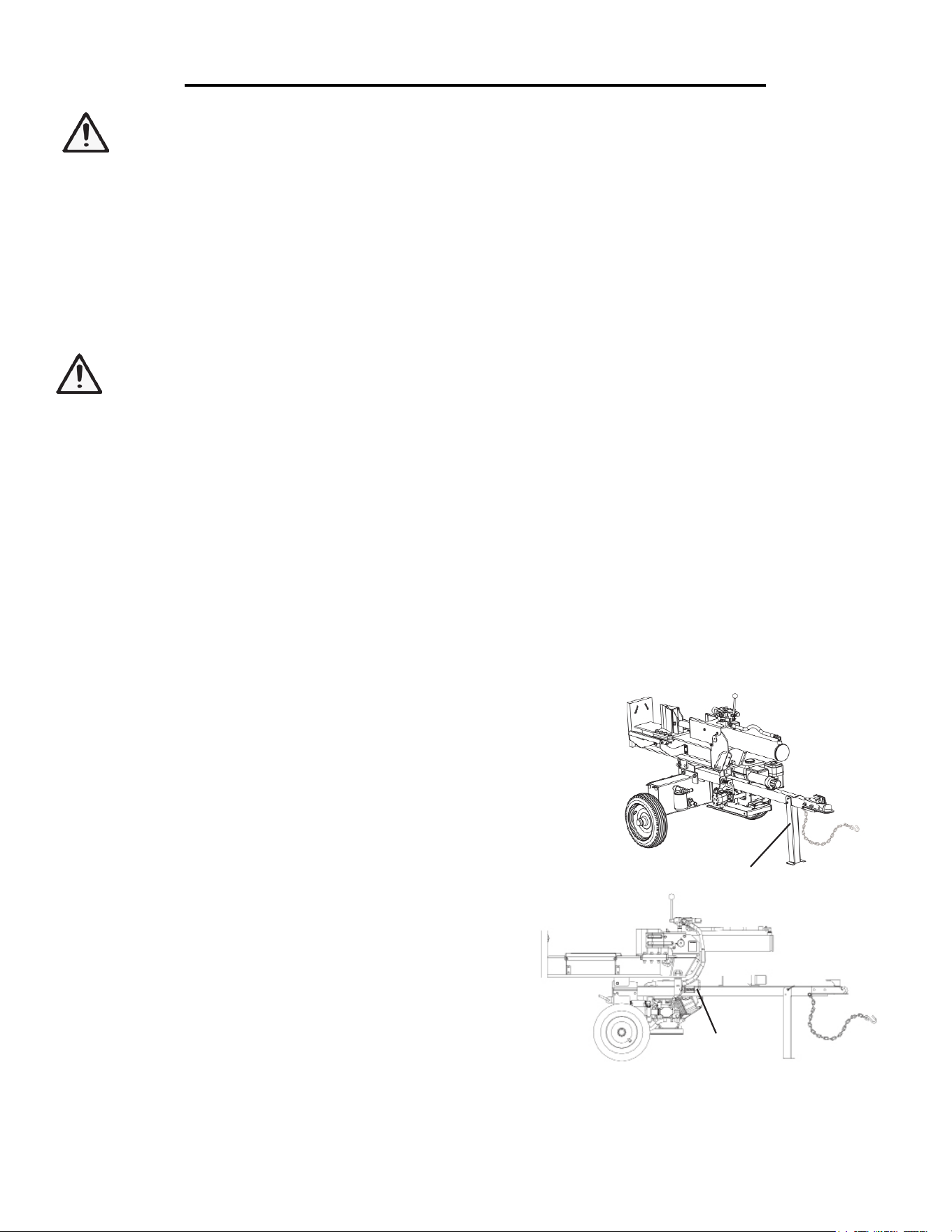
SAFETY WHILE MOVING:
Horizontal position. Make sure the log splitter is secured in the horizontal position before moving the log
splitter. DO NOT move the log splitter when it is in the vertical position because it will be unstable and could tip.
Turn engine o. Never move the log splitter with its engine running.
SAFETY DURING TOWING:
1. Securely attach the log splitter to the towing vehicle before towing.
2. Be sure the tires are fully inated and in good condition before towing the log splitter. When adding air
to the tires, do not over-inflate, as this could result in serious injury if the tire explodes.
3. Never tow this log splitter over 45 mph. Faster speeds may result in loss of control.
4. Rough terrain: be extra cautious and drive slowly when traveling over rough terrain.
5. Stay sober: never tow this splitter while under the influence of alcohol, drugs, or medication.
6. If towing on a public road, make sure to comply with all local, state, and federal towing requirements. It
is the sole responsibility of the purchaser to obtain licensing, trailer lights, safety chains, signage, or any other legal
requirements needed in the area of towing.
7. Turn o the towing vehicle before leaving the splitter unattended.
8. Disconnect before operating. Do not use the log splitter while it is connected to the towing vehicle.
SAFETY DURING USE
1. Always block the wheels to prevent unintended movement of the log splitter.
2. Safety equipment/controls: always operate the log splitter with all safety equipment in place and in good
working order, and all controls properly adjusted for safe operation.
3. Know how to stop: be thoroughly familiar with all controls and with the proper use of the equipment. Know
how to stop the log splitter and relieve system pressures quickly if needed.
4. Daylight only: Only use the log splitter in daylight so you can see what you are doing.
5. Smoking/sparks: never smoke while operating the log splitter, and never operate near sources of sparks or
flames.
6. Hot muer: if you are starting a warm engine, stay clear of muffler. It may still be hot enough to burn you.
7. Never leave the machine unattended while the engine is running.
8. Stay sober: never operate the log splitter while under the influence of alcohol, drugs, or medication.
9. Other exhaust dangers. Engine exhaust, some of its constituents, and certain vehicle components contain
or emit chemicals known to the State of California to cause cancer, birth defects, or other reproductive harm.
Avoid excess inhalation of exhaust.
6
IMPORTANT SAFETY INSTRUCTIONS
10. Only uses square log ends: logs that are not cut square can slide out while splitting and become a safety
hazard or cause excessive force to log splitter components. Use a chain saw to cut logs square on each end before
attempting to split them.
11. Single log: never attempt to split more than one log at a time. Pieces of log can unexpectedly be thrown
from the machine causing serious injury.
12. Split along grain: do not use the log splitter to split logs across the grain. Doing so will damage the log
splitter and can also cause pieces of log to be thrown, injuring the operator or bystanders.
13. Keep hands clear: ALWAYS keep hands and feet away from the end plate, wedge, and partially split logs
while loading, operating and unloading the log splitter.
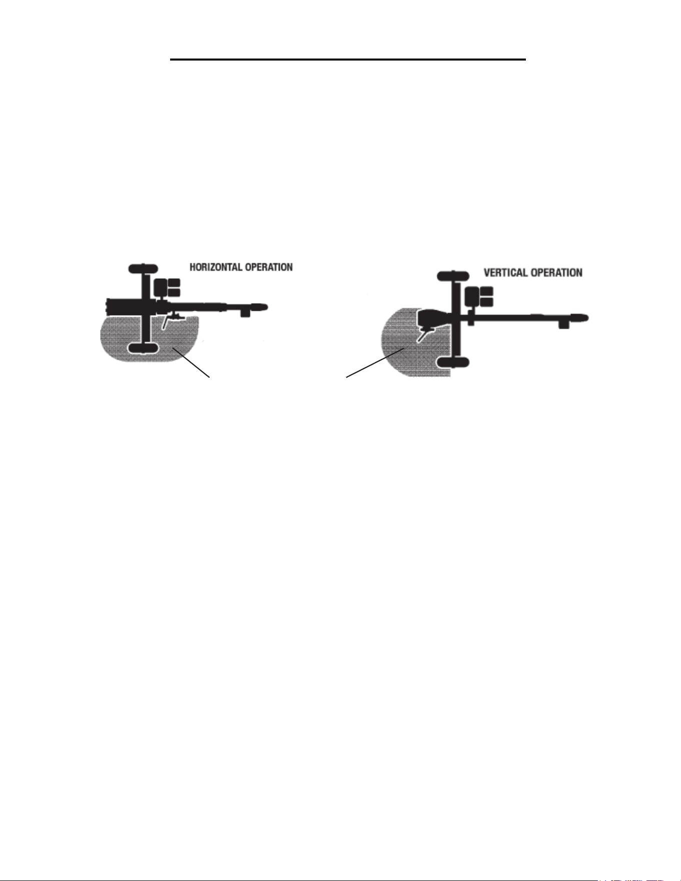
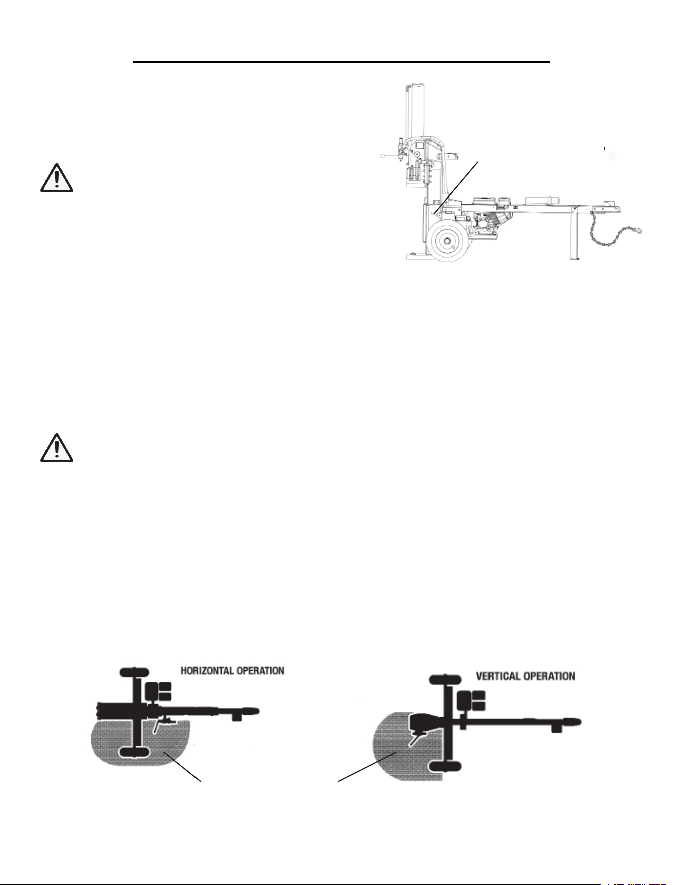
14. Operator position: ALWAYS operate the log splitter from the operation zone as shown below. Other
positions are unsafe because they can increase the risk of injury from crushing, cutting, flying objects, or burns.
15. Never straddle, reach across or step over the beam while the engine is running and the log splitter is
in the horizontal position. You could trip, actuate the controls, and get seriously injured.
16. Avoid using a second person during operation: many accidents occur when there is more than one
person involved in loading and operating the log splitter. Only one person should operate the controls. If a second
person is assisting in loading logs, the operator must NEVER actuate the Split Control Lever until the assistant
and all bystanders are at least 10 feet away. NEVER allow an assistant to hold the log in place while the operator
actuates the Split Control Lever.
17. NEVER load or unload logs while the wedge is moving.
18. Keep hands clear: remove both hands from log before activating Split Control Lever.
19. Only use your hands to operate the Split Control Lever. Never use any other body part, a rope, cable,
or other remote device to actuate the control.
20. Returning wedge: once the control valve is actuated in the return direction, the wedge is designed to keep
returning by itself completely and then stop automatically. Stay clear while the wedge is returning. It is still power-
ful enough on the return stroke to cause serious injury.
21. For stuck logs: if a log does not split completely and becomes stuck on the wedge, follow the instructions
below to remove the log. A log can become stuck to the wedge if the wedge becomes embedded in the log and the
log doesn’t split and separate. This can happen if the log is too stringy or tough to split completely. A stuck log will
move back with the wedge on the initial attempt to retract the wedge. If this happens, retract the wedge completely
to allow the splitter to strip the log from the wedge. Keep hands clear of log and wedge while wedge is retracting.
OPERATION ZONE
7
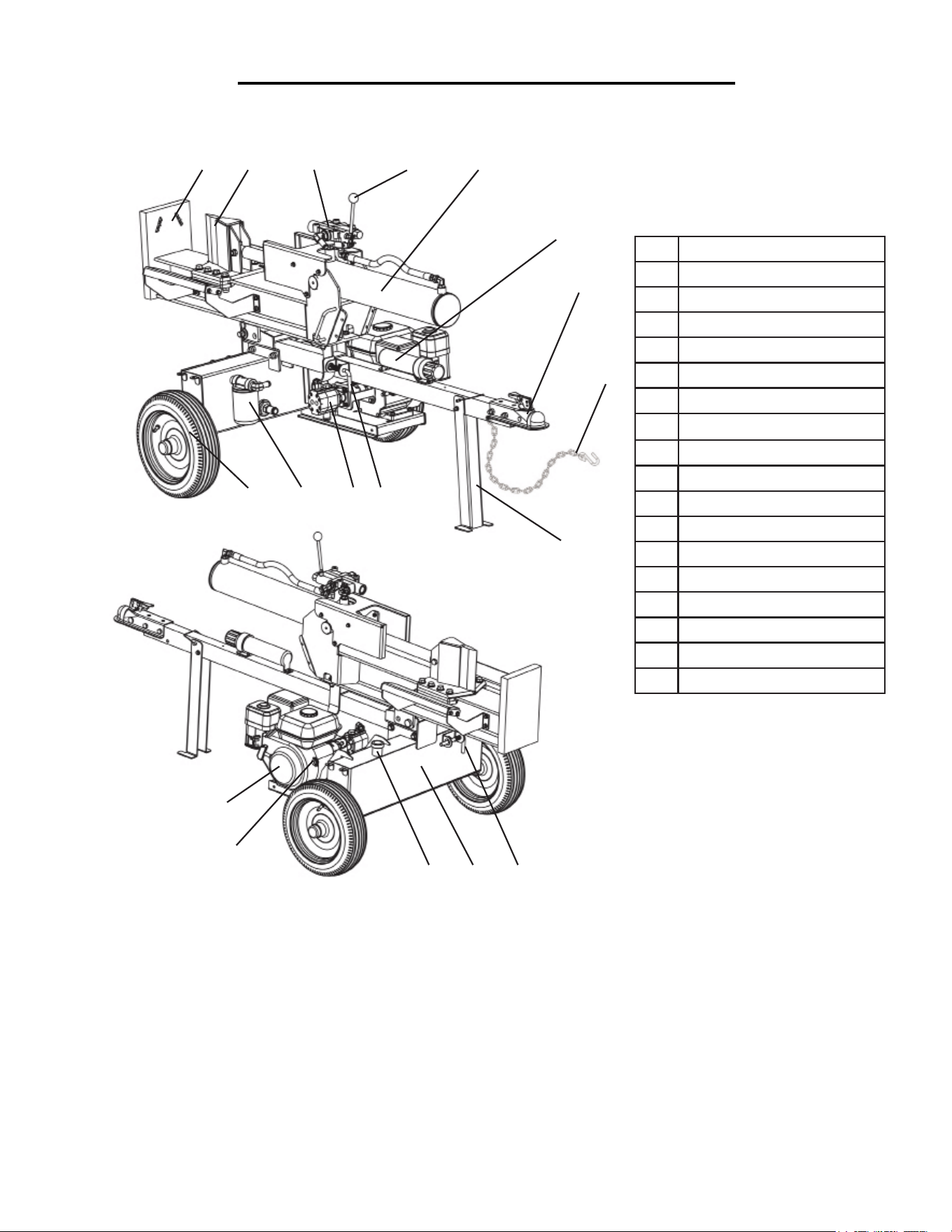
LOG SPLITTER COMPONENTS
Use the illustrations below to become familiar with the locations and functions of the various components and
controls of this log splitter.
1 End Plate
2 Wedge
3 Control Valve
4 Split Control Lever
5 Cylinder
6 Manual Tube
7 2” Ball Coupler
8 Safety Chain
9 Support Leg
10 Horizontal Lock
11 Pump
12 Return Line Filter
13 Tire
14 Engine
15 Engine ON/OFF Switch
16 Hydraulic Dipstick
17 Hydraulic Tank
18 Vertical Lock
Closely inspect all log splitter components
If you have missing or damaged components, please contact WEN Customer Service at 1-800-232-1195.
1
2
4
5
6
7
8
9
10
12
1113
14
15
16 17
18
3
8
ASSEMBLY
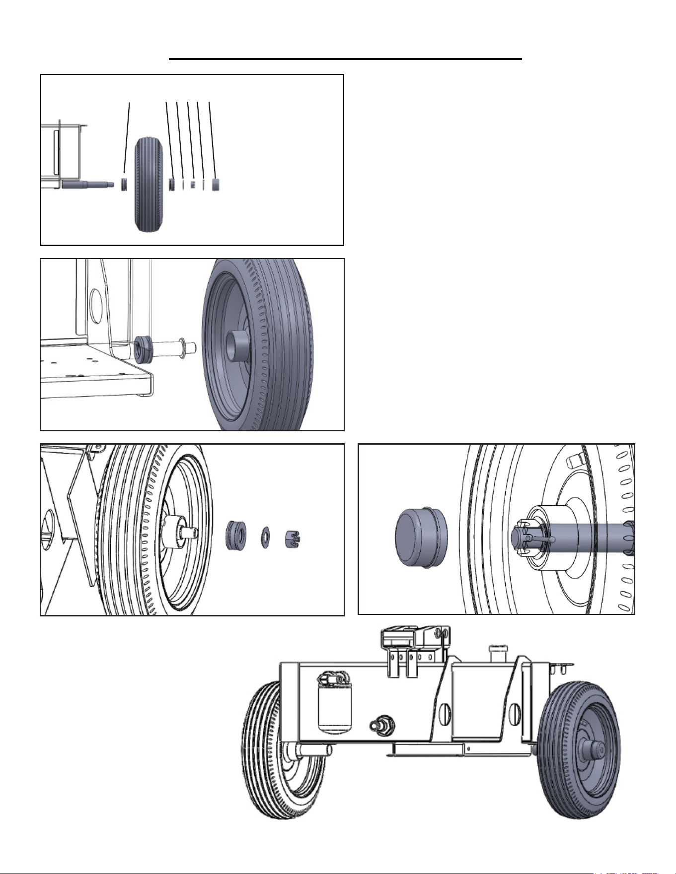
STEP 1 - ATTACHING THE TIRES TO THE
HYDRAULIC TANK (FIGURE 1)
1. Slide a bearing (1A) and the tire onto axle with the
valve stem (valve for inflation) facing out (Figure 1A)
(bearings 1A and 1B may already be mounted on the
tire).
2. Slide the other bearing (1B), a washer (2) and the
slotted castle nut (3) onto the axle. Using a wrench,
tighten the nut. Turn hub to ensure the bearings are
seated properly. Make sure the tire spins freely (Fig-
ure 1B)
3. Insert cotter pin (4) through the hole in the slotted
castle nut (3) and axle. Bend and spread prongs in
opposite directions so the axle nut will not come off
(Figure 1C).
4. Install the hub cap (4). Gently tap on the hub cap
with a hammer to drive the hub cap into place (Figure
1C).
5. Repeat these steps to install the other tire.
1A
2
3
4
1A - Bearing
1B - Bearing
2 - Washer
3 - Castle Nut
4 - Cotter Pin
5 - Hub Cap
1B
5
Figure 1A
Figure 1B Figure 1C
Figure 1
Caution: Heavy lifting required.
Some of the components in these
assembly instructions are heavy
and cannot be safely lifted by one
person. Please plan on assembling
this product when another person
can be available to help out.
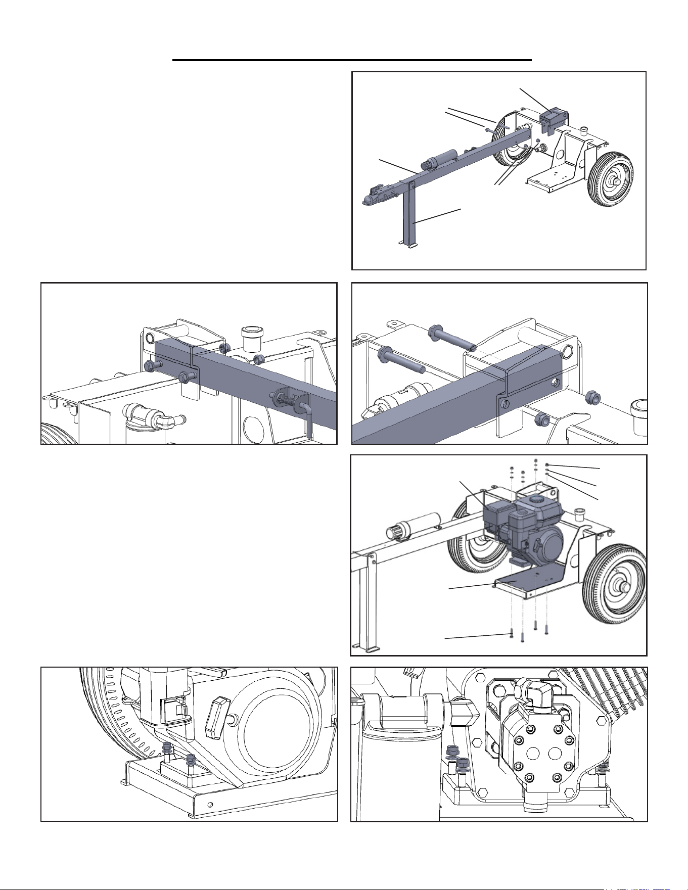
9
ASSEMBLY
1. Lock the support leg (4) in its downward position be-
fore starting.
2. Slide the tow bar (1) into the pivot mount (3). Fasten
it in place using the included bolts (2) and nuts (5) as
shown in Figures 2A and 2B.
1. Tow Bar
2. Bolts
3. Pivot Mount
4. Support Leg
5. Nuts
1
2
3
4
5
STEP 2 - ATTACHING THE TOW BAR TO
THE HYDRAULIC TANK (FIGURE 2)
Figure 2BFigure 2A
STEP 3 - ATTACHING THE ENGINE TO
THE HYDRAULIC TANK (FIGURE 3)
1. Place the engine (1) as shown in position on top of the
engine mount plate (5).
2. Install the engine to the engine mount plate using bolts,
washers and nuts. Make sure to insert the bolt from the
bottom side of the engine mount plate as shown in Fig-
ure 3.
5
6
Figure 2
Figure 3A
Figure 3B
Figure 3
1
2
3
4
1. Engine
2. Nuts (4)
3. Spring Washers (4)
4. Top Washers (4)
5. Engine Mount Plate
6. Bolts (4)
10
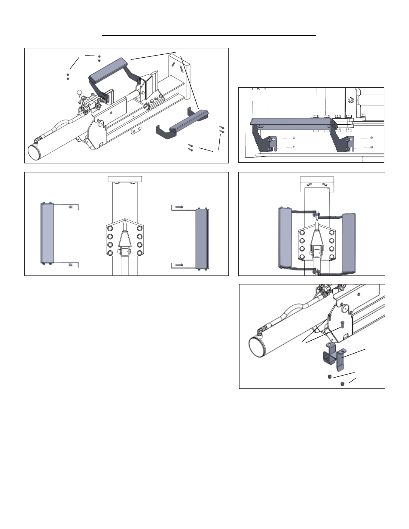
ASSEMBLY
STEP 4 - ASSEMBLING THE LOG
CRADLES (FIGURE 4)
Attach the two log cradles (2) to beam using
four bolts (3) and four locknuts (1).
1
2
3
1. Nuts (4)
2. Log Cradles (2)
3. Bolts (4)
Figure 4
Figure 4A
Figure 4B Figure 4C
STEP 5 - ASSEMBLE THE BEAM LOCK BRACKET
(FIGURE 5)
1. Run the two hoses emerging from either side of the control
valve to the underside of the log splitter as shown in Figure 5A
(next page).
2. Fasten the beam lock bracket using the included bolts and nuts.
Make sure that the bracket encloses the two hoses as shown in
Figure 5B (next page).
1
2
3
1. Bolts (2)
2. Beam Lock Bracket
3. Nuts (2)
Figure 5
STEP 6 - ATTACHING THE ASSEMBLED BEAM TO THE HYDRAULIC TANK (FIGURE 6)
1. Stand the assembled beam (4) onto its end plate in the vertical position with the pivot bracket (5) facing the
pivot mount (1) (Figure 6, next page). Make sure an associate helps hold the beam assembly in place to prevent it
from tipping over and inflicting injury.
2. Align the beam pivot bracket (5) with the pivot mount (1). Insert the pivot pin (2) (Figure 6A & 6B, next page).
3. Insert the cotter pin (3) through the hole in the beam pivot pin (4). Spread and bend the prongs of the cotter
pin in opposite directions to secure it in place. Once the pin is secure, lower the assembly beam into the horizon-
tal position with the help of your associate (final horizontal position should look similar to Figure 7C).
11
ASSEMBLY
Figure 5A
Figure 5B
1
2
3
4
5
1. Pivot Mount
2. Beam Pivot Pin
3. Cotter Pin
4. Beam Assembly
5. Beam Pivot Bracket
Figure 6
Figure 6A
Figure 6B
Figure 6C
12
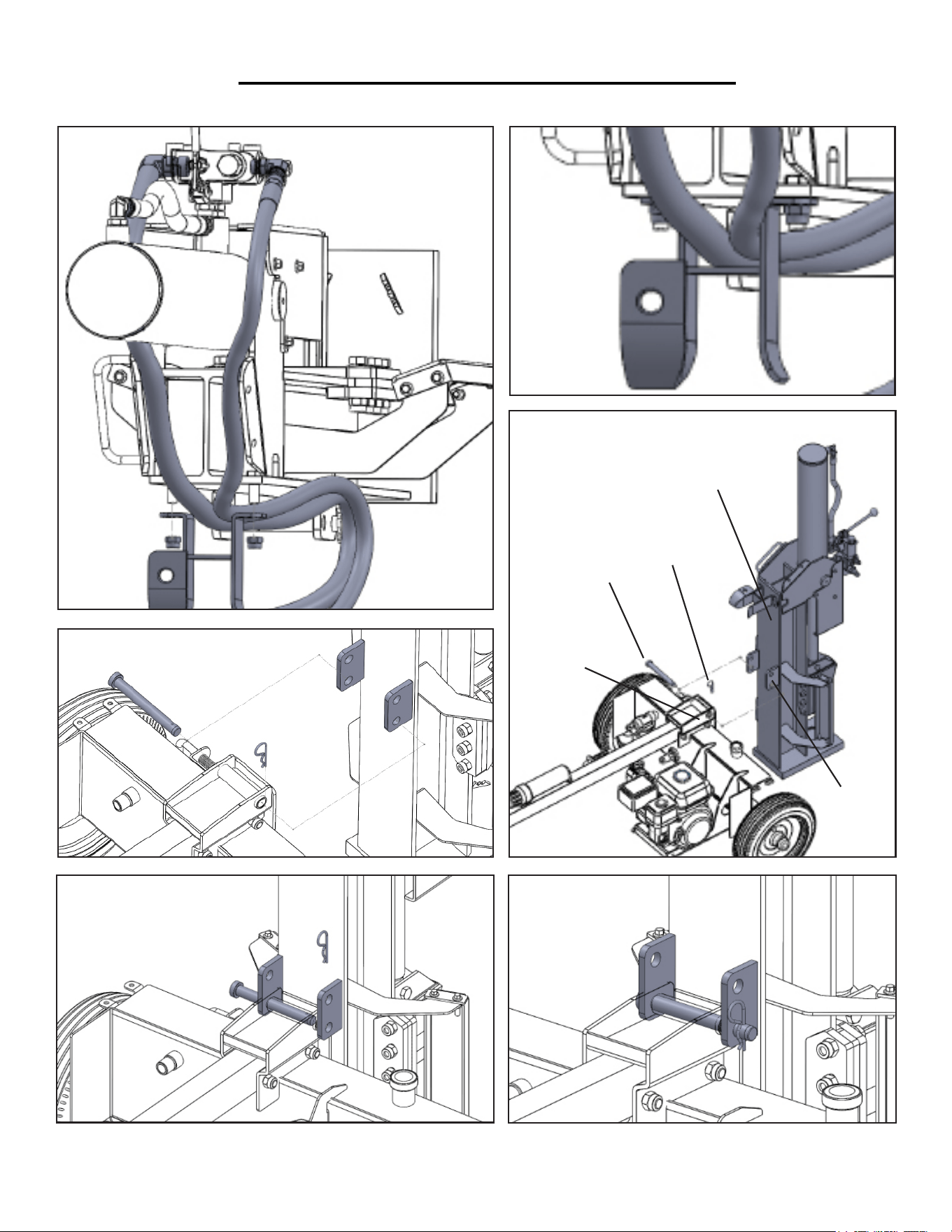
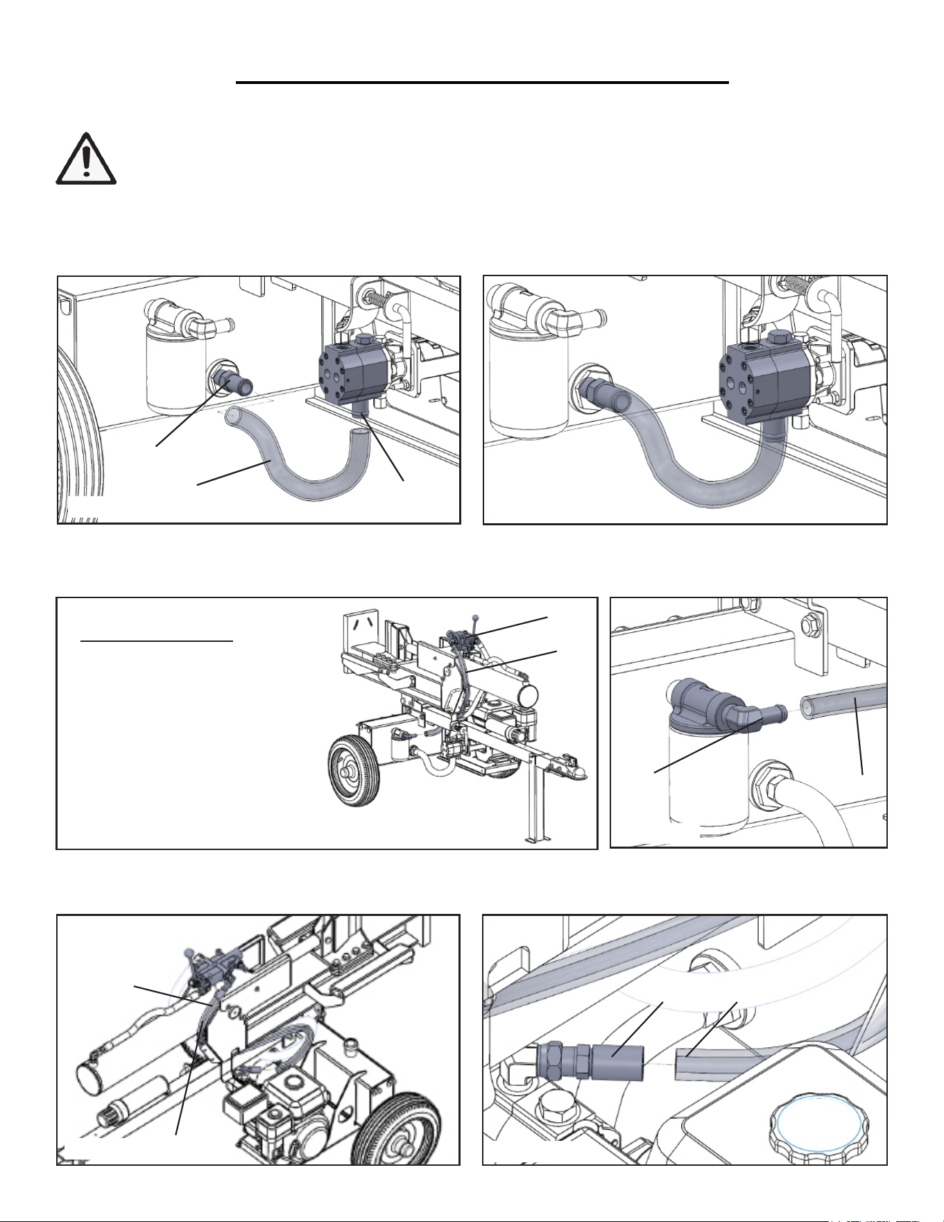
ASSEMBLY
STEP 7 - CONNECTING THE HOSES
1. Connect one end of the suction hose (2) to the tank suction port (1) and the other end to the pump inlet (3) as
shown in Figure 7A. Tighten the supplied hose clamps on both sides (torque to 75 in.-lb.) (Figure 7A)
1
2
3
Figure 7A
Figure 7B
Figure 7C
Figure 7D
2. Grab the low pressure return hose (4) emerging from the side of the control valve (5) opposite of the engine.
Attach the free end to the return line filter fitting (6). Torque to 75 in.-lb. (Figure 7C and 7D).
4
6
4
3. Route the high pressure hose (7) emerging from the engine-side of the control valve (5) down to the pump’s
outlet fitting (8). Wrench tighten three to five turns past hand tight.
Figure 7E
Figure 7F
5
5
7
8 7
For Figures 7A to 7F
1. Tank Suction Port
2. Suction Hose
3. Pump Inlet Fitting
4. Low Pressure Return Hose
5. Control Valve
6. Return Line Filter Fitting
7. High Pressure Hose
8. Pump Outlet Fitting
WARNING: Be extremely careful when connecting the hoses. Connecting the hose to the wrong
port could quickly ruin your log splitter and also runs the risk of inflicting an unwanted injury. Double
check that the hoses are running to the correct inlets and outlets before starting the log splitter.
13
USING THE LOG SPLITTER FOR THE FIRST TIME
The following section describes steps necessary to prepare the
log splitter for use. If after reading this section, you are unsure
about how to perform any of the steps please call (800) 232-1195
M-F 8-5 CST for customer service. Failure to perform these
steps properly can damage the log splitter or shorten its life.
Step 1 - ADD OIL
The log splitter is shipped without oil. User must add the proper amount
of oil before operating the log splitter for the first time. The oil capacity
of the engine crankcase is 20 fluid oz. For general use (above 40° F), we
recommend 30W, 4-stroke engine oil.
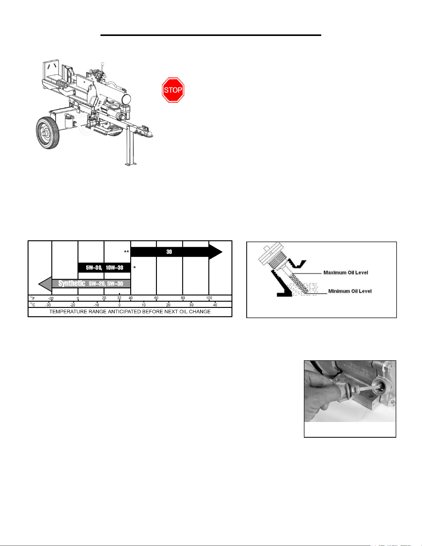
ENGINE OIL RECOMMENDATIONS
Select good quality detergent oil bearing the American Petroleum Institute (API) service classifications SJ, SL, or
SM. (Synthetic oils may be used.) Use the ASE viscosity grade of oil from the following chart that matches the start-
ing temperature anticipated before the next oil changes.
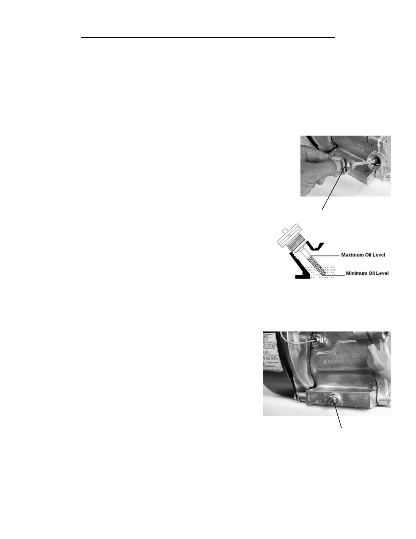
To add oil, follow these steps:
1. Make sure the log splitter is on a level surface.
2. Remove the dipstick from the engine.
3. Add oil slowly to bring level to full.
4. To check the oil level: wipe the dipstick with a clean rag. Insert the dipstick into
the oil fill opening without screwing in. Remove the dipstick to check the oil mark.
5. Slowly add more oil and repeat step 4 until the oil mark reaches to the top of the
dipstick. Do not overfill the crankcase. The log splitter is equipped with a low oil
sensor and will not start if the amount of oil is insufficient.
6. Check for oil leaks. Tighten dipstick.
LOG SPLITTER PREPARATION
Oil Dipstick
Oil Fill Opening, Dipstick
and Oil Level
Engine Oil Recommendations

14
Step 2 - ADD GASOLINE
WARNING: The engine may emit highly ammable and explosive gasoline vapors,
which can cause severe burns or even death if ignited. A nearby open ame can lead to
explosion even if not directly in contact with gasoline.
Use fresh (within 30 days from purchase) lead-free gasoline with a minimum of 87 octane rating. Do not mix oil
with gasoline.
To add gasoline, follow these steps:
1. Make sure the log splitter is on a level surface.
2. Unscrew fuel cap and set aside. NOTE: The fuel cap may be tight and hard to unscrew.
3. Slowly add unleaded gasoline to the fuel tank. Be careful not to overfill. The capacity of the fuel tank is 1 gallon.
NOTE: Do not fill the fuel tank to the very top. Gasoline will expand and spill over during use even with the fuel
cap in place.
4. Reinstall fuel cap and wipe clean any spilled gasoline with a dry cloth.
IMPORTANT:
• Never use an oil/gasoline mixture.
• Never use old gasoline.
• Avoid getting dirt or water into the fuel tank.
• Gasoline can age in the tank and make starting difficult. Never store fuel in the tank for extended periods of time.
LOG SPLITTER PREPARATION
Step 3 - ADD HYDRAULIC FLUID
The log splitter is shipped without hydraulic fluid. Users must add the proper amount of hydraulic fluid before
operating the log splitter for the first time. The hydraulic fluid capacity of the log splitter is 6.5 gallons.
5 gallon of hydraulic fluid is the minimum required to operate. After putting in fluid for the first time, run the log
splitter a few times. Afterwards, add more fluid if needed.
WARNING: High fluid pressures and temperatures are developed in hydraulic log splitters. Hydraulic
fluid escaping through a pin-hole sized opening can burn or puncture skin, resulting in wounds that could
cause blood poisoning, infection, disability, gangrene, amputation, or death. Therefore, the following instructions
should be heeded at all times when inspecting or servicing the hydraulic components of the log splitter.
NEVER check for leaks with your hand. Leaks can be located by holding a piece of cardboard or wood (at least two
feet long) with your hand at one end and passing the other end over the suspected area (wear eye protection). Look
for discoloration of the cardboard or wood.
NEVER adjust the pressure of the pump or valve.
If injured by escaping fluid, no matter how small the wound is, see a doctor at once. A typical injection injury may
be a small wound that does not look serious. However, severe infection or reaction can result if proper medical
treatment is not administered immediately by a doctor who is familiar with injection injuries.
Before starting the log splitter, make sure you have read and performed the steps in the “Assembly” and the
“Log Splitter Preparation” section of this manual. If you are unsure about how to perform any of the steps in this
manual please call (800) 232-1195 M-F 8-5 CST for customer service before attempting to start the log splitter.
DANGER: CARBON MONOXIDE.
Using a log splitter indoors CAN KILL YOU IN MINUTES.
Log splitter exhaust contains carbon monoxide (CO). This is a poison gas you cannot see or smell. If you can
smell the log splitter exhaust, you are breathing CO. Even if you cannot smell the exhaust, you may be breathing
CO.
NEVER use a log splitter inside homes, garages, crawl spaces, or other partly enclosed areas. Deadly levels of car-
bon monoxide can build up in these areas. Using a fan or opening windows and doors does NOT supply enough
fresh air.
ONLY use a log splitter outside and far away from windows, doors, and vents. These openings can pull in log
splitter exhaust. Even if you use a log splitter correctly, CO may leak into the home. ALWAYS use a battery-pow-
ered or battery-backup CO alarm in the home.
If you start to feel sick, dizzy, or weak after the log splitter has been running, move to fresh air RIGHT AWAY.
See a doctor. You may have carbon monoxide poisoning.
NOTE: After completing the above preparation, the log splitter is ready to be started.
15
STARTING THE LOG SPLITTER
LOG SPLITTER PREPARATION
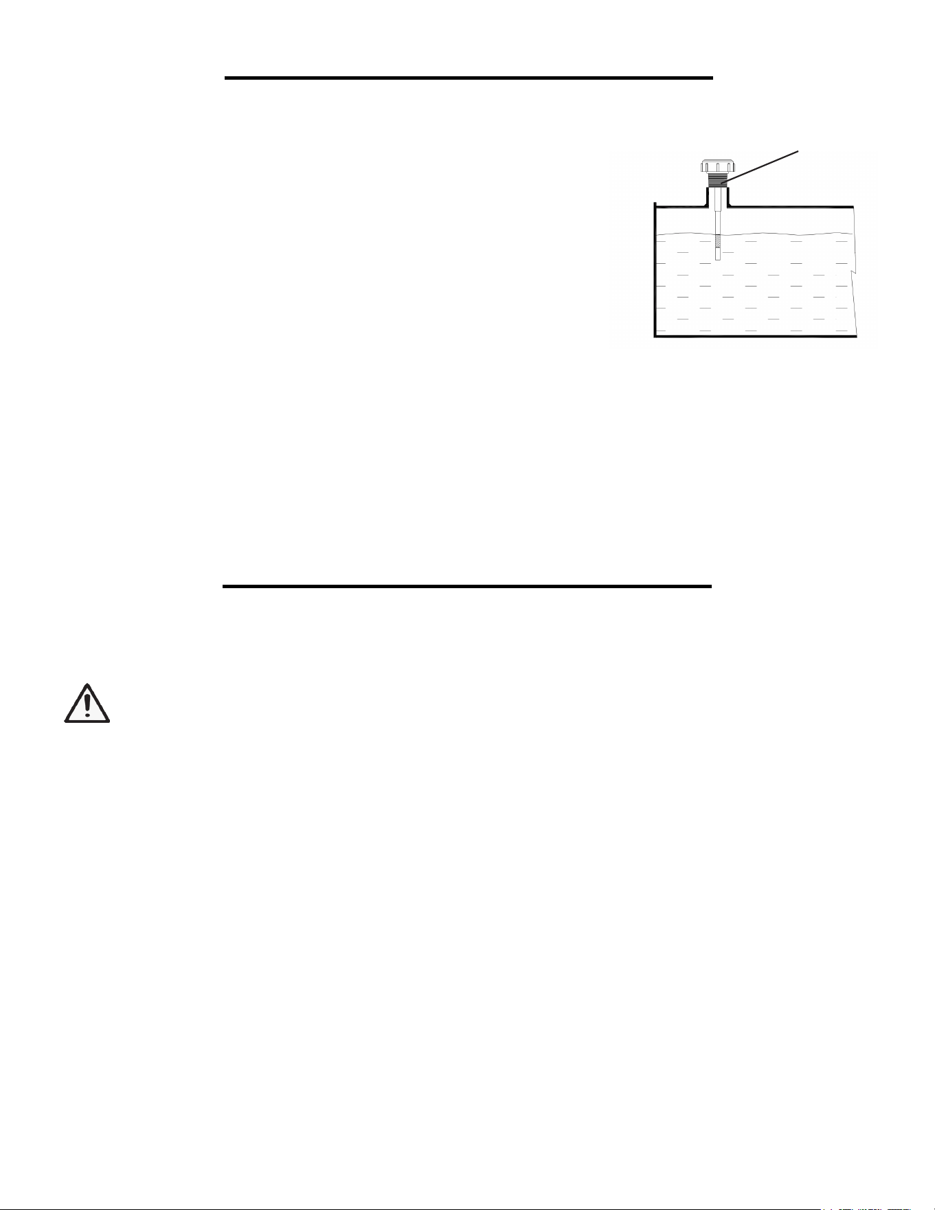
HOW TO ADD HYDRAULIC FLUID
1. Remove hydraulic dipstick.
2. Fill hydraulic tank with 10 wt AW32, ASLE H-150, or ISO 32 oil. Use a
funnel if need.
3. Remove hydraulic dipstick and check the level. Note: Do not screw in
dipstick when checking levels.
3. Start engine and use split control lever to extend and retract wedge five
times to remove air from the hydraulic system.
4. With wedge retracted, check oil level again.
Hydraulic Dipstick
16
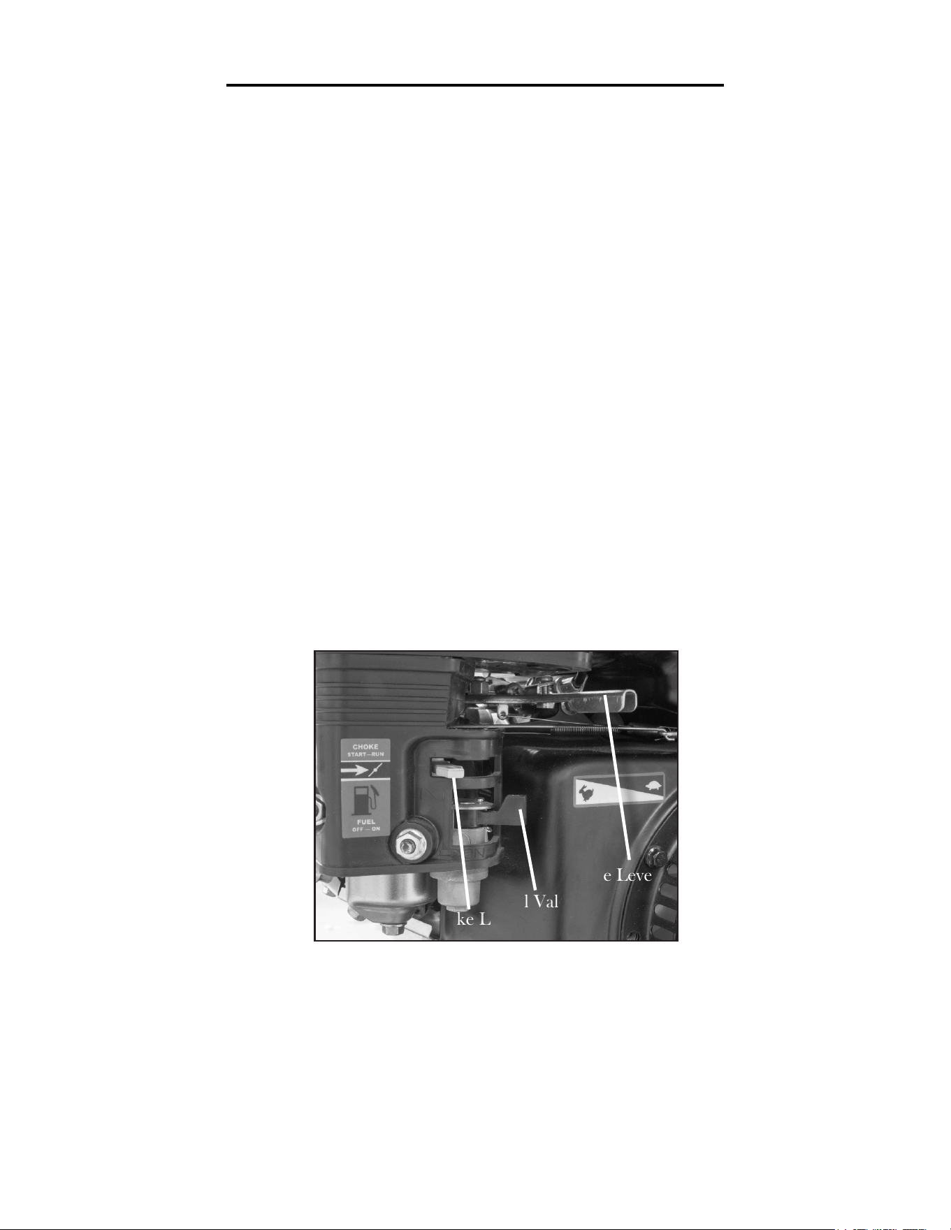
STARTING THE ENGINE
To start the engine, perform the following steps:
1. Check the oil, fuel and hydraulic fluid levels.
2. Push the Fuel Valve to “ON” position, moving the fuel valve over to the right as shown.
3. Move the Choke Lever to “START” position by sliding it over to the left.
4. Set the engine switch to the “ON” position.
5. Slide the Throttle Lever 1/3 away from the SLOW position (the turtle).
6. Pull on the recoil starter handle slowly until a slight resistance is felt. Then pull quickly to start the engine. Re-
turn cord gently into the machine. Never allow the cord to snap back.
7. If engine fails to start, repeat step 9. NOTE: After repeated failed attempts to start the engine, please call (800)
232-1195 M-F 8-5 CST.
8. Once the engine has started, slowly return the choke lever all the way to the “RUN” position by moving the
choke lever back to the right.
9. Allow the engine to run for several minutes at no load. This allows the engine to stabilize its speed and tem-
perature.
10. Adjust the throttle as needed.
Allow the engine to run for several minutes before using the log splitter. This allows the log splitter to stabilize its
speed and temperature.
STARTING THE LOG SPLITTER
Fuel Valve
Throttle Lever
Fuel Valve
Choke Lever

17
STOPPING THE LOG SPLITTER
If this is not the first time using the log splitter, the user should take the following steps to prepare it for
operation.
IMPORTANT: At this point the user should be familiar with the procedures described in the
section titled “Log Splitter Preparation.” If the user has not yet read this section, go back and
read it now.
Step 1 - CHECK THE OIL
Oil consumption is normal during log splitter use. The engine is equipped with a low-oil pressure shutoff to
protect it from damage. The oil level of the engine should be checked before each use to ensure that the engine
crankcase contains sufficient lubricant.
To check or add oil, follow these steps:
1. Place the log splitter on a level surface.
2. Clean around oil fill hole. Remove dipstick and wipe the dipstick with a clean rag. Insert the dipstick into the oil
fill opening without screwing it in. Remove the dipstick to check the oil mark. Add oil if the oil mark covers less
than one half of the dipstick.
3. Slowly add more oil and repeat step 2 until the oil mark reaches to the top of dipstick. Do not over fill the
crankcase.
4. Tighten dipstick firmly before starting the engine.
Step 2 - CHECK THE FUEL LEVEL
Before starting the log splitter, check to see that there is sufficient gasoline in the fuel tank. Add additional gaso-
line as necessary but leave sufficient room in tank for expansion.
SUBSEQUENT STARTING OF THE LOG SPLITTER
TO TURN OFF THE LOG SPLITTER
WARNING: Allow the engine to cool for several minutes before touching areas that become hot during
use.
CAUTION: Allowing gasoline to sit in the fuel tank for long periods of time can make it difficult to
start the engine in the future. Never store the log splitter for extended periods of time with fuel in the
fuel tank.
1. Retract the wedge completely to keep the rod protected from corrosion.
2. Turn the engine ON/OFF switch to the OFF position to shut down the engine.
3. Slide the fuel valve to the OFF position (slide to the left).
4. Return the log splitter to horizontal position.
18
SUBSEQUENT STARTING OF THE LOG SPLITTER
WARNING: This engine may emit highly flammable and explosive gasoline vapors, which can cause
severe burns or even death if ignited. A nearby open flame can lead to explosion even if not directly in
contact with fuel.
• Do not operate near open flame.
• Do not smoke near log splitter.
• Always operate on a firm, level surface.
• Always turn log splitter off before refueling. Allow engine to cool for at least 2 minutes before removing fuel
cap. Loosen cap slowly to relieve pressure in tank.
• Do not overfill fuel tank. Gasoline may expand during operation. Do not fill to the top of the tank. Allow for
expansion.
• Always check for spilled fuel before operating. Clean up any spilled fuel before starting.
• Empty fuel tank before storing or transporting the log splitter.
• Before transporting, turn fuel valve to the off position.
IMPORTANT:
• Use only UNLEADED gasoline.
• Do not use old gasoline.
• Never use an oil/gasoline mixture.
• Avoid getting dirt or water into the fuel tank.
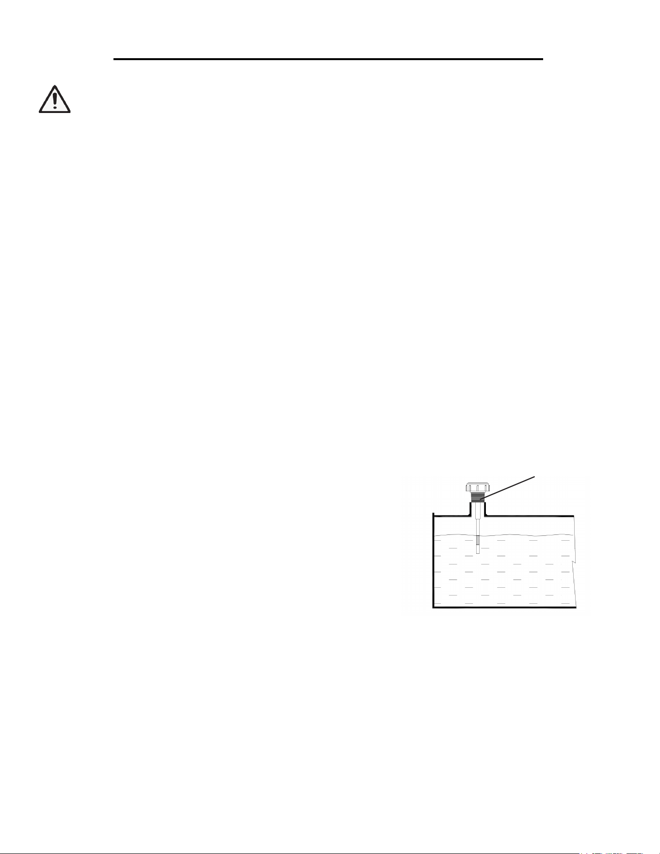
Step 3 - CHECK THE HYDRAULIC FLUID LEVEL
1. Remove hydraulic dipstick and check the hydraulic fluid level. Note: Do not screw in dipstick when checking
oil level.
2. If needed, add additional hydraulic fluid.
Hydraulic Dipstick
19
USING THE LOG SPLITTER
WARNING: It is important to select an appropriate work site and properly set up the log splitter in
order to minimize the risk of slips and falls, equipment rolling or tipping over, carbon monoxide poison-
ing, and accidental fires.
SELECT LOCATION
Make sure to find a dry level surface with good footing for operation. Stay clear of areas with mud, ice, tall grass,
weeds, brush, or snow. Always use the log splitter outdoors, away from air intakes.
Muffler should be at least seven feet from any combustible objects during operation. Hot exhaust fumes from the
engine could cause a fire. Also, hydraulic oil leaking or spraying on the hot engine can result in a fire.
WARNING: The running engine gives off carbon monoxide, a poisonous gas that can kill you. You
CANNOT smell it, see it, or taste it. ONLY run the log splitter OUTDOORS and away from air intakes.
NEVER run the log splitter inside homes, garages, sheds, or other buildings or semi-enclosed spaces.
These spaces can trap poisonous gases, EVEN if you run a fan or open windows.
If you start to feel sick, dizzy, or weak while using the log splitter, shut off the engine and get to fresh air RIGHT
AWAY. See a doctor. You may have carbon monoxide poisoning.
FIRE PRECAUTIONS
Make sure you comply with applicable local, state and federal codes.
Keep a fire extinguisher available (classified for both ordinary combustibles & flammable liquids) as a precaution-
ary measure when operating the log splitter in dry areas.
LOCK DOWN SUPPORT LEG & BLOCK WHEELS
Lock the support leg in the DOWN position.
Block the wheels to prevent unintended movement of the log splitter.
Support Leg
SET TO HORIZONTAL POSITION
Make sure the beam is locked securely in the horizontal position
by checking the horizontal lock.
Horizontal Lock
20
USING THE LOG SPLITTER
SET TO VERTICAL LOCK
Pull out horizontal lock latch rod, grasp and lift beam until it
rotates into vertical position.
WARNING: Crush hazard. The beam is heavy – do
not let it just drop. It could crush fingers or cause dam-
age to the splitter.
Lock in vertical position using latch rod through the vertical
lock.
To return to horizontal position, unlock vertical latch rod,
grasp and lower beam carefully in a controlled manner until it rests on the tow bar then lock beam in the hori-
zontal position with latch rod.
Vertical Lock
LOAD LOG
Load log onto beam with a cut end against the end plate – positioned for a lengthwise cut.
CAUTION: The log splitter is designed only for cutting lengthwise with the grain —NOT for cutting across the
grain. This log splitter is designed for cutting logs only up to a maximum of 14” in diameter and 25” long. Larger
diameter logs could get stuck on the wedge and longer logs will not fit on the beam.
WARNING: Always keep hands and feet away from the end plate, wedge, and partially
split logs while loading, operating and unloading the log splitter.
For vertical position loading: place the log on the end plate and turn it until it leans stably against the beam. If the
log is too big or oddly shaped, stabilize the log with wooden shims between the log and end plate or ground. DO
NOT use your leg or knee to stabilize the log. NEVER stabilize the log by placing your hand on top of the log.
OPERATOR POSITION
ALWAYS operate the log splitter from the operation zone as shown below. Other positions are unsafe because
they can increase the risk of injury from crushing, cutting, flying objects, or burns. Keep bystanders away.
OPERATION ZONE

USING THE LOG SPLITTER
EXTENDING AND RETURNING THE WEDGE
CAUTION: Remove both hands from log before activating Split Control Lever. Use only your hand to operate
the Split Control Lever. Never use any other body part, or a rope, cable, or other remote device to actuate the
control.
Many accidents occur when there is more than one person involved in loading and operating the log splitter.
Only one person should operate the controls. If a second person is assisting in loading logs, the operator must
NEVER actuate the Split Control Lever until the assistant and all bystanders are at least 10 feet away. NEVER
allow an assistant to hold the log in place while the operator actuates the Split Control Lever.
Move the Split Control Lever towards the end plate to extend the wedge and split the log.
Release Split Control Lever to stop wedge movement and return the wedge once the log has been split. Once the
Split Control Lever has been returned to its return position, the wedge is designed to continue returning by itself
completely until it retracts all the way back and stops automatically.
21

MAINTENANCE & CARE
Proper routine maintenance of the log splitter will help prolong the life of the machine. Please perform mainte-
nance checks and operations according to the schedule outlined in the chart below.
If there are any questions about the maintenance procedures listed in this manual, please call (800) 232-1195 M-F
8-5CT.
CAUTION: Never perform maintenance operations while the engine is running.
Recommended
Maintenance Schedule
Each 8
hours or
daily
First 8
hours
Every 25
hours
Every 3
months or
50 hours
Every 6
months or
100 hours
Every
year
As
Necessary
Engine oil Check
level
x
Replace x x* x* x
Air
cleaner
cartridge
Check x x
Clean x
Spark plug Check/
clean
x
Change x x
Hydraulic
Fluid
Check
lever
x
Replace x
Fuel tank Check
level
x
Clean x
Recommended maintenance schedule
* Clean/change more often under dusty conditions or when operating under heavy load.
22
23
CLEANING THE LOG SPLITTER
Never clean the log splitter when it is running! Never clean with a bucket of water or a hose.
If the log splitter becomes dirty, clean the exterior with a damp cloth, a soft brush, a vacuum or pressurized air.
CHECKING THE OIL
Check the oil level of the engine according to the Recommended Maintenance
Schedule (page 22). The engine is equipped with an automatic shutoff to protect it
from running on low oil. The engine should be checked before each use for proper
oil level. This is a critical step for proper engine starting. To check the oil level:
1. Make sure the log splitter is on a level surface.
2. Remove dipstick and wipe the dipstick with a clean rag. Insert the dipstick into the
oil fill opening without screwing it in. Remove the dipstick to check the oil mark. Add
oil if the oil mark covers less than one half of the dipstick.
3. Slowly add more oil and repeat step 2 until the oil mark reaches the top of
the dipstick. Do not overfill the crankcase.
4. Reinstall oil dipstick.
MAINTENANCE & CARE
CHANGING/ADDING OIL
Change the oil according to the Recommended Maintenance Schedule.
Change the oil when the engine is warm. This will allow for complete
drainage. Change oil more often if operating under heavy load or high
ambient temperatures. It is also necessary to drain the oil from the
crankcase if it has become contaminated with water or dirt. The oil
capacity of the engine is 20 fl.oz. Add oil when the oil level is low. For
proper type and weight of oil refer to “Step 1 - Add Oil” portion of the
“Log Splitter Preparation” section.
Drain the oil from the engine according to the following steps.
1. Place the log splitter on a level surface.
2. Unscrew the drain bolt from the engine and set aside.
3. After draining, install the drain bolt and tighten it securely.
4. Fill the crankcase with fresh oil and reinstall the dipstick. Clean any oil spillage.
Oil Dipstick
Oil Fill Opening, Dipstick and
Oil Level
Drain Bolt

24
MAINTENANCE & CARE
To rell the crankcase with oil, follow these steps:
1. Make sure the log splitter is on a level surface.
2. Remove the dipstick from the engine.
3. Using a funnel or appropriate dispenser, add the correct amount of oil into the crankcase. The engine is
equipped with a low-oil pressure sensor and will not start if the amount of oil is insufficient.
4. Reinstall dipstick.
NOTE: Never dispose of used motor oil in the trash or down a drain. Please call a local recycling center or auto
garage to arrange oil disposal.
AIR CLEANER MAINTENANCE
Routine maintenance of the air cleaner helps maintain proper airflow to the carburetor. Occasionally check that
the air cleaner is free of excessive dirt. Refer to Recommended Maintenance Schedule.
1. Remove the wing nut and the air cleaner cover. Remove the element and separate them. Carefully check ele-
ment for holes or tears and replace if damaged.
2. Clean element with household detergents and warm water. Rinse thoroughly. Allow the element to dry com-
pletely.
3. Soak element in clean engine oil and squeeze out the excess oil. Engine will smoke if too much oil is left on
foam.
4. Reinstall the filter element and air cleaner housing.
CAUTION: running the engine with dirty, damaged or missing air cleaner element will cause the engine to wear
out prematurely.
CHECK TIRES
Make sure tires are fully inflated and in good repair.
Warning: Do not over-inflate tires. Serious injury can occur if tires explode.
After any repair to the tire, do not exceed 30 PSI when filling with air. Pressures higher than 30 PSI can
cause the tire and wheel to rupture and explode.
MAINTENANCE & CARE
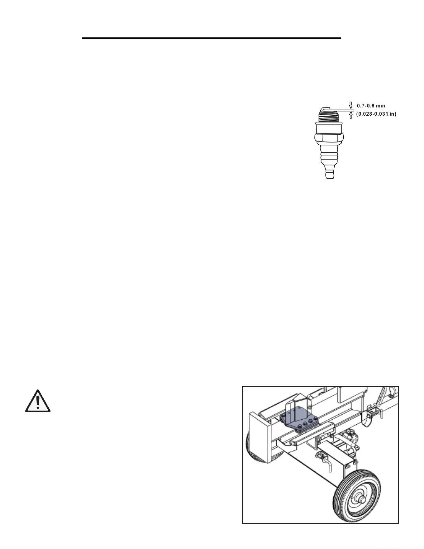
SPARK PLUG MAINTENANCE
The spark plug is important for proper engine operation. A good spark plug should be intact, free of deposits,
and properly gapped. Refer to Recommended Maintenance Schedule. To inspect the spark plug:
1. Remove spark plug boot. Be careful not to tear insulation or wire.
2. Unscrew the spark plug from the engine using the spark plug wrench provided.
There is limited space for the wrench to turn. Use both rows of holes in the spark
plug wrench to gain leverage to loosen the plug.
3. Visually inspect the spark plug for cracks or excessive electrode wear. Replace
as necessary.
4. Measure the plug gap with a wire gauge. The gap should be 0.6-0.7 mm (0.024-
0.028 in).
5. If re-using the spark plug, use a wire brush to clean any dirt from around the spark plug base then re-gap the
spark plug.
6. Screw the spark plug back into the spark plug hole using the spark plug wrench. Do not over-tighten spark
plug. Recommended tightening of spark plug is ½ to ¾ of a turn after spark plug gasket contacts spark plug hole.
Reinstall the spark plug boot.
HYDRAULIC SYSTEM MAINTENANCE
1. Visually inspect all hoses, tubing, clamps/fittings, pump, and cylinders for cracks, fraying, kinks, or other dam-
age.
2. Check all components for oily residue, as this may indicate a leak.
CAUTION: Do NOT operate the log splitter if there is any indication of damage or oily residue. Small leaks in
hydraulic lines can cause severe injuries and can also be an indication of catastrophic failure in the near future.
The life of hydraulic hoses may be from a few months to a few years, depending on use and storage patterns.
Warning: High fluid pressures and temperatures are
developed in hydraulic log splitters. Hydraulic fluid
escaping through a pin-hole sized opening can burn
or puncture skin, resulting in wounds that could cause
blood poisoning, infection, disability, gangrene, amputation, or
death.
APPLY GREASE
Routinely apply grease to the beam. This will help prevent wear
between the wedge and beam.
25
Routinely apply
grease to the under-
side of the wedge
(highlighted).

26
STORAGE & TRANSPORT
Return to horizontal. If in the vertical position, turn off engine and return log splitter to the horizontal posi-
tion for greater stability during transportation. Avoid contact with the muffler and the surrounding area, as these
parts may be hot.
Remove engine debris. Debris on a hot engine can be a fire hazard. With the engine off, clear debris and
chaff from engine cylinder head, cylinder head fins, blower housing rotating screen, and muffler areas. Avoid
contact with hot muffler.
Let engine cool before storing. Let the engine cool for at least five minutes before storing. A hot engine can
be a fire hazard.
Storage location. Store the log splitter in a location away from sources of heat, open flames, sparks or pilot
lights – such as water heaters, space heaters, furnaces, clothes dryers, or other gas appliances. Even if the log split-
ter’s gas tank is empty, residual gasoline vapors could ignite.
Gasoline storage. Store extra gasoline in a cool, dry place in a UL listed, tightly-sealed container. Gasoline
vapors can ignite if they collect inside an enclosure.

27
SPECIFICATIONS
Engine
Engine type 4 stroke, OHV, single cylinder with forced air cooling system
Spark plug gap 0.6 - 0.7 mm (0.024 - 0.028 in)
Spark plug torque 1/2 - 3/4 turn after gasket contacts base or 15 ft.lb
Displacement 212 cc
Fuel tank capacity 1 gallon 87 octane minimum
Oil capacity 0.37 quarts (0.35 liters)
Lubrication system Splash lubrication
Run time on 50% load 4 hours
Noise rating 63 dB at 22 feet
Spark plug A5RTC
Log Splitter
Model 56230
Ram Force 30 Ton
Continuous Force 28 Ton
Max. Log Length 25”
Max. Log Width 14” Diameter.
Pressure 3500 PSI
Cylinder 4.5” Dia. x 24” Stroke
Hydraulic Fluid Capacity 7 Gallons
Hydraulic Fluid Type 10wt AW32, ASLE H-150, or ISO32
Pump 12 GPM, 2 Stage
Valve Auto Return with Adjustable Detent
Cycle Time 14 Seconds
Wedge 7” High, Heat-Treated Steel
Coupler 2” Ball
Max. Towing Speed 45 MPH
Wheel 16”
Weight (No Oil) 442 lbs
28
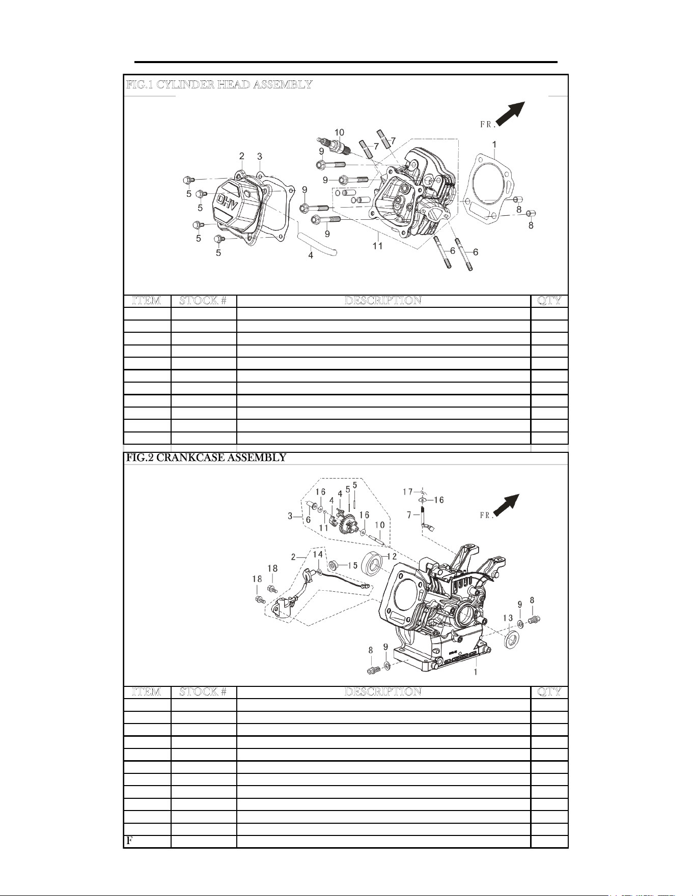
ENGINE EXPLODED VIEW AND PARTS LIST
ITEM STOCK # DESCRIPTION QTY
Fig01-1 56212-0101 GASKET, CYLINDER HEAD 1
Fig01-2 56212-0102 COVER, CYLINDER HEAD 1
Fig01-3 56212-0103 GASKET, CYLINDER HEAD COVER 1
Fig01-4 56212-0104 TUBE, BREATHER 1
Fig01-5 56212-0105
BOLT 4
Fig01-6 56212-0106
STUD 2
Fig01-7 56212-0107 STUD 2
Fig01-8 56212-0108 PIN 2
Fig01-9 56212-0109 BOLT, CYLINDER HEAD 4
Fig01-10 56212-0110 PLUG, SPARK 1
Fig01-11 56212-0111 HEAD ASSEMBLY, CYLINDER 1
ITEM STOCK # DESCRIPTION QTY
Fig02-1 56212-0201 CRANKCASE ASSEMBLY 1
Fig02-2 56212-0202 SENSOR, ENGINE OIL 1
Fig02-3 56212-0203 GEAR ASSEMBLY, GOVERNOR 1
Fig02-7 56212-0207 ARM, GOVERNOR 1
Fig02-8 56212-0208 BOLT, DRAIN PLUG 2
Fig02-9 56212-0209 WASHER 2
Fig02-12 56212-0212 BEARING 1
Fig02-13 56212-0213 SEAL, OIL 1
Fig02-15 56212-0215 NUT 1
Fig02-16 56212-0216 WASHER 1
Fig02-17 56212-0217 PIN 1
Fig02-18 56212-0218 BOLT 2
FIG.1 CYLINDER HEAD ASSEMBLY
FIG.2 CRANKCASE ASSEMBLY
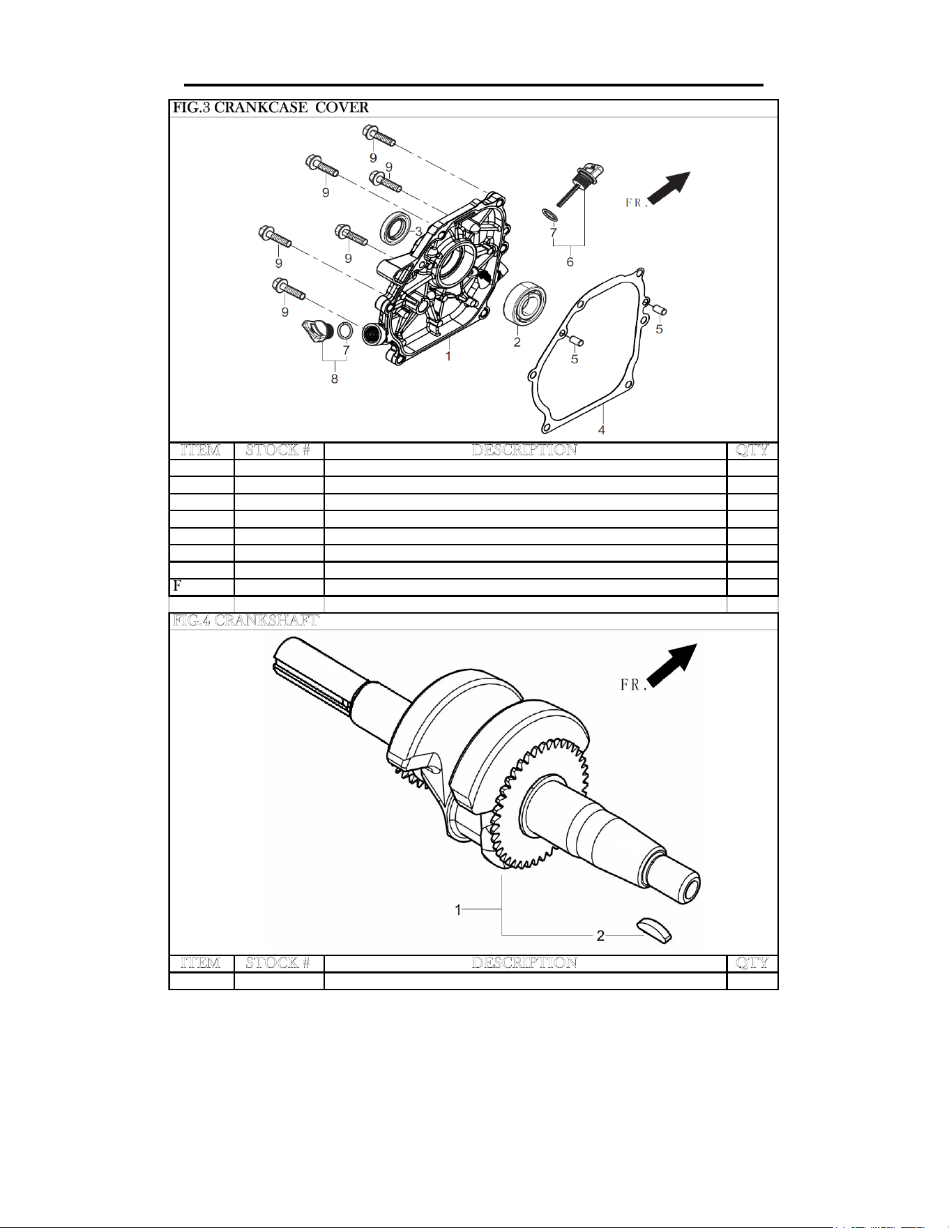
29
ITEM STOCK # DESCRIPTION QTY
Fig03-1 56212-0301 COVER, CRANKCASE 1
Fig03-2 56212-0302 BEARING 1
Fig03-3 56212-0303 SEAL, OIL 1
Fig03-4 56212-0304 GASKET, CRANKCASE 1
Fig03-5 56212-0305 PIN 2
Fig03-6 56212-0306 DIPSTICK ASSEMBLY, OIL 1
Fig03-8 56212-0308 PLUG ASSEMBLY, ENGINE OIL 1
Fig03-9 56212-0309 BOLT 6
ITEM STOCK # DESCRIPTION QTY
Fig04-1 56212-0401 CRANKSHAFT ASSEMBLY 1
FIG.4 CRANKSHAFT
FIG.3 CRANKCASE COVER
ENGINE EXPLODED VIEW AND PARTS LIST
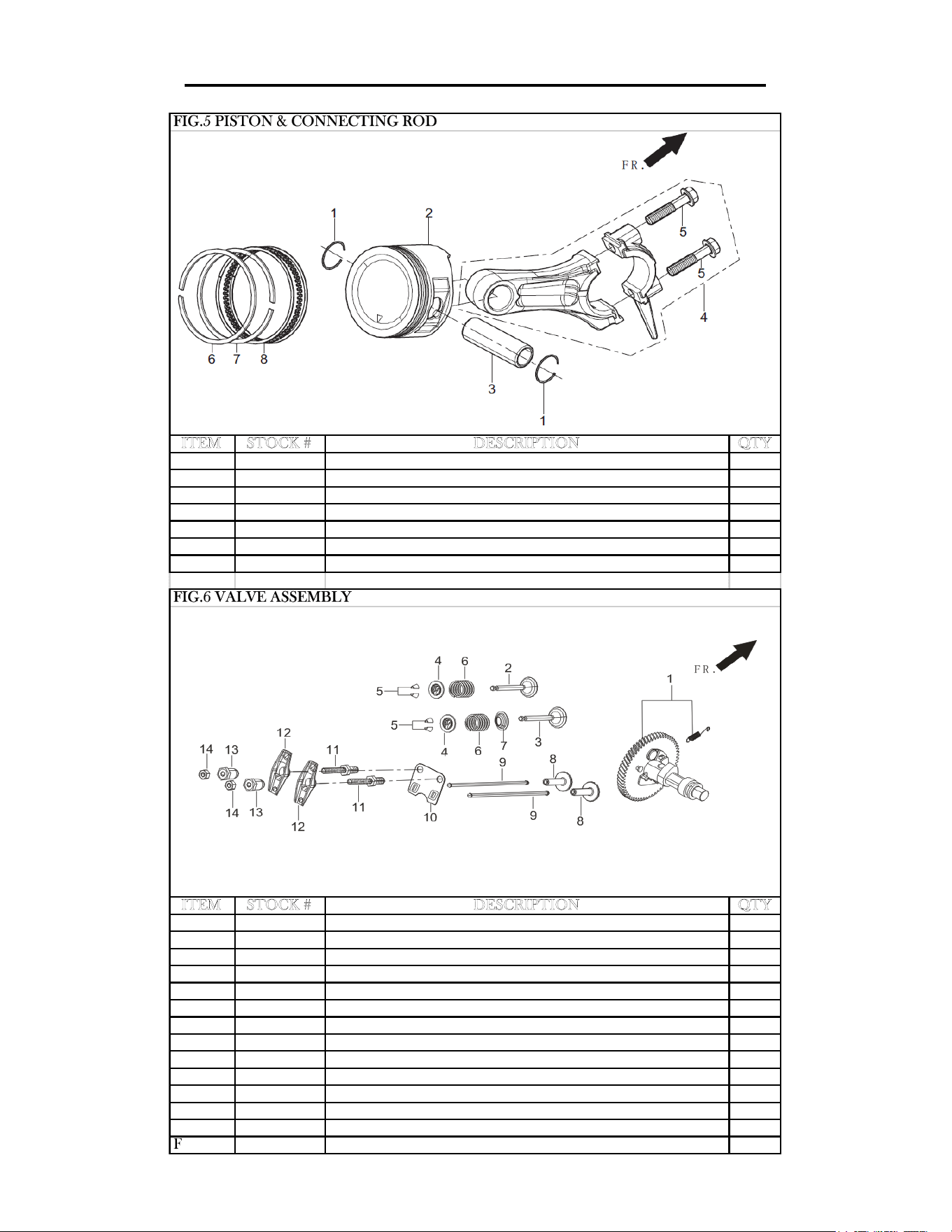
30
ITEM STOCK # DESCRIPTION QTY
Fig05-1 56212-0501 CLIP, PISTON PIN 2
Fig05-2 56212-0502 PISTON 1
Fig05-3 56212-0503 PIN, PISTON 1
Fig05-4 56212-0504 ROD, CONNECTING 1
Fig05-6 56212-0506 RING, THE FIRST 1
Fig05-7 56212-0507 RING, THE SECON 1
Fig05-8 56212-0508 RING SET, OIL 1
ITEM STOCK # DESCRIPTION QTY
Fig06-1 56212-0601 CAMSHAFT ASSEMBLY 1
Fig06-2 56212-0602 VALVE, EXHAUST 1
Fig06-3 56212-0603 VALVE, INTAKE 1
Fig06-4 56212-0604 SEAT, VALVE SPRING 2
Fig06-5 56212-0605 VALVE LOCK 4
Fig06-6 56212-0606 SPRING, VALVE 2
Fig06-7 56212-0607 GUIDE, SEAL 1
Fig06-8 56212-0608 TAPPET, VALVE 2
Fig06-9 56212-0609 LIFTER, VALVE 2
Fig06-10 56212-0610 PLATE ASSEMBLY, LIFTER STOPPER 1
Fig06-11 56212-0611 BOLT, VALVE ADJUSTING 2
Fig06-12 56212-0612 ROCKER, VALVE 2
Fig06-13 56212-0613 NUT, VALVE ADJUSTING 2
Fig06-14 56212-0614 NUT, VALVE LOCK 2
FIG.6 VALVE ASSEMBLY
FIG.5 PISTON & CONNECTING ROD
ENGINE EXPLODED VIEW AND PARTS LIST
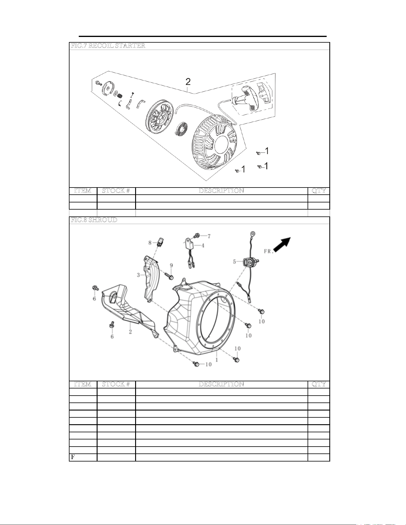
31
ENGINE EXPLODED VIEW AND PARTS LIST
ITEM STOCK # DESCRIPTION QTY
Fig07-1 56212-0701 BOLT 3
Fig07-2 56212-0702 STARTER ASSEMBLY, RECOIL 1
ITEM STOCK # DESCRIPTION QTY
Fig08-1 56212-0801 SHROUD 1
Fig08-2 56212-0802 SHROUD, CYLINDER BODY 1
Fig08-3 56212-0803 SHIELD,LOWER 1
Fig08-4 56212-0804 PROTECTOR, OIL 1
Fig08-5 56212-0805 ENGINE SWITCH 1
Fig08-6 56212-0806 BOLT 2
Fig08-7 56212-0807 BOLT 1
Fig08-8 56212-0808 COLLAR 1
Fig08-9 56212-0809 BOLT 1
Fig08-10 56212-0810 BOLT 4
FIG.8 SHROUD
FIG.7 RECOIL STARTER
32
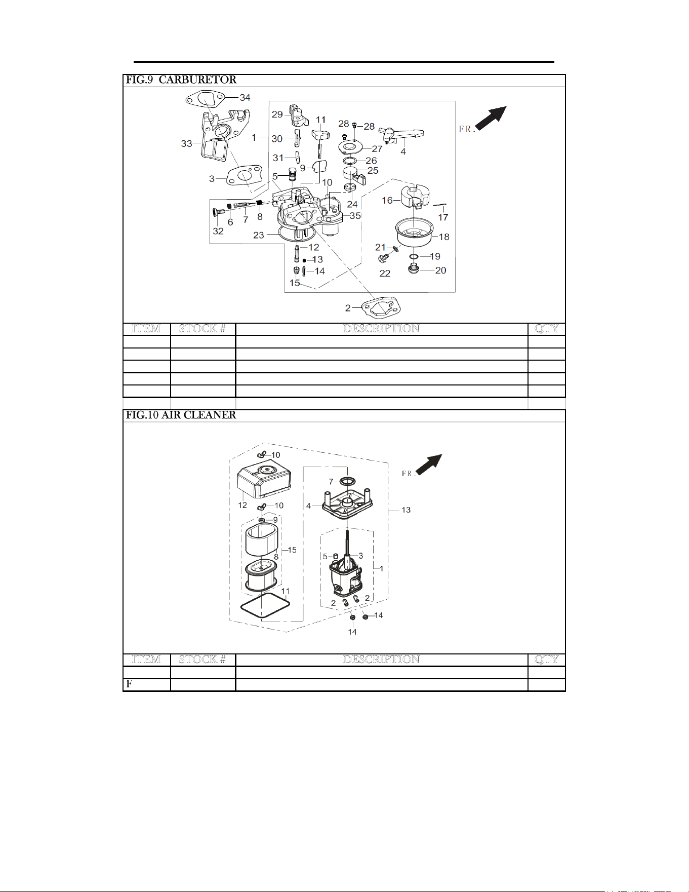
ENGINE EXPLODED VIEW AND PARTS LIST
ITEM STOCK # DESCRIPTION QTY
Fig09-1 56212-0901 CARBURETOR ASSEMBLY 1
Fig09-2 56212-0902 GASKET, AIR CLEANER 1
Fig09-3 56212-0903 GASKET, CARBURETOR 1
Fig09-33 56212-0933 PLATE, CARBURETOR INSULATOR 1
Fig09-34 56212-0934 GASKET, CARBURETOR INSULATOR 1
ITEM STOCK # DESCRIPTION QTY
Fig10-13 56212-1013 CLEANER, AIR 1
Fig10-14 56212-1014 NUT 2
FIG.9 CARBURETOR
FIG.10 AIR CLEANER
33
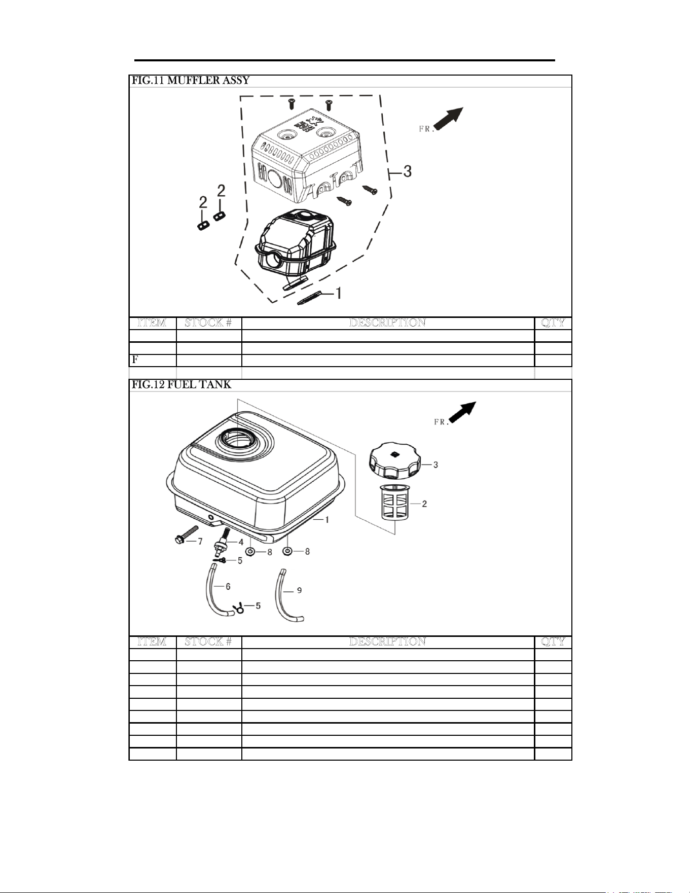
ENGINE EXPLODED VIEW AND PARTS LIST
ITEM STOCK # DESCRIPTION QTY
Fig11-1 56212-1101 GASKET, EXHAUST OUTLET 1
Fig11-2 56212-1102 NUT 2
Fig11-3 56212-1103 MUFFLER ASSEMBLY 1
ITEM STOCK # DESCRIPTION QTY
Fig12-1 56212-1201 TANK, FUEL 1
Fig12-2 56212-1202 STRAINER,FUEL 1
Fig12-3 56212-1203 COVER, FUEL TANK 1
Fig12-4 56212-1204 OUTLET ASSEMBLY, FUEL TANK OIL 1
Fig12-5 56212-1205 COLLAR 2
Fig12-6 56212-1206 TUBE, FUEL 1
Fig12-7 56212-1207 BOLT 1
Fig12-8 56212-1208 NUT 2
Fig12-9 56212-1209 JACKET, RUBBER 1
FIG.11 MUFFLER ASSY
FIG.12 FUEL TANK
34
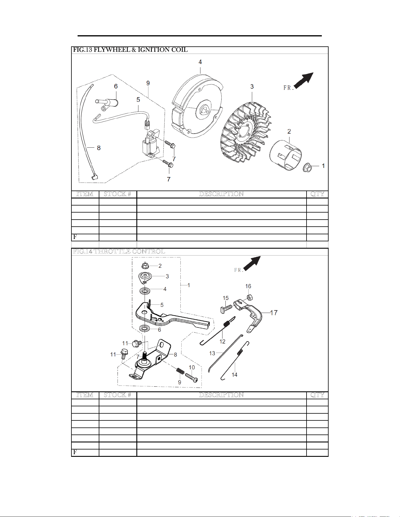
ENGINE EXPLODED VIEW AND PARTS LIST
ITEM STOCK # DESCRIPTION QTY
Fig13-1 56212-1301 NUT, FLYWHEEL 1
Fig13-2 56212-1302 PULLEY,STARTER 1
Fig13-3 56212-1303 IMPELLER 1
Fig13-4 56212-1304 FLYWHEEL ASSEMBLY 1
Fig13-7 56212-1307 BOLT 2
Fig13-9 56212-1309 COIL, IGNITION 1
ITEM STOCK # DESCRIPTION QTY
Fig14-1 56212-1401 CONTROL ASSEMBLY, THROTTLE 1
Fig14-11 56212-1411 BOLT 2
Fig14-12 56212-1412 SPRING, GOVERNOR 1
Fig14-13 56212-1413 ROD, GOVERNEOR 1
Fig14-14 56212-1414 SPRING, THROTTLE VALVE RETURNING 1
Fig14-15 56212-1415 BOLT, GOVERNOR SUPPORT 1
Fig14-16 56212-1416 NUT 1
Fig14-17 56212-1417 SUPPORT ASSEMBLY, GOVERNOR 1
FIG.13 FLYWHEEL & IGNITION COIL
FIG.14 THROTTLE CONTROL
35
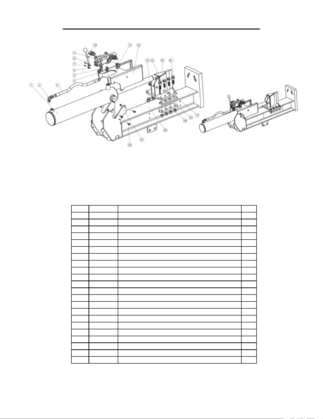
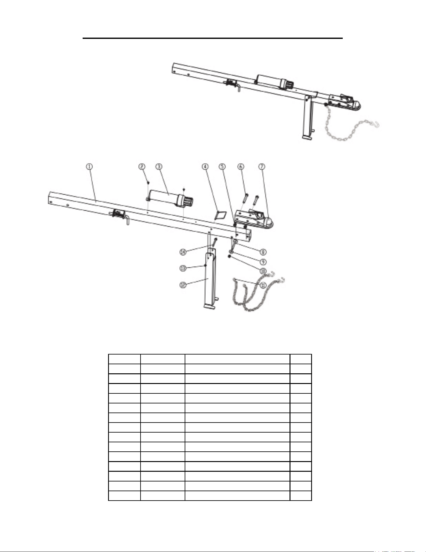
LOG SPLITTER EXPLODED VIEW AND PARTS LIST
BEAM ASSEMBLY
ITEM STOCK# DESCRIPTION QTY
1 56227-0101 CYLINDER ASSEMBLY 1
2 56222-0102 HIGH PRESSURE FITTING FOR CYLINDER 1
3 56222-0103 HIGH PRESSURE HOSE FOR CYLINDER 1
4 56222-0104 VALVE MOUNT FITTING 1
5 56222-0105 HIGH PRESSURE FITTING FO CYLINDER 1
6 56222-0106 VALVE HANDLE COTTER PIN 2
7 56222-0107 VALVE HANDLE PINES 2
8 56222-0108 VALVE HANDLE 1
9 56222-0109 CONTROL VALVE 1
10 56222-0110 RETURN FITTING FOR VALVE 1
11 56222-0111 OIL-IN HIGH PRESSURE FITTING FOR VALVE 1
12 56222-0112 LOG STRIPPER COVER 1
13 56222-0113 NUT M14 1
14 56222-0114 BOLT M14X70 1
15 56222-0115 WEDGE 1
16 56222-0116 BOLT M14X60 8
17 56222-0117 SPACER FOR WEDGE 2
18 56222-0118 BASE PLATE FOR WEDGE 2
19 56222-0119 NUT M14 8
20 56222-0120 BEAM WELDMENT 1
21 56222-0121 NUT M8 6
22 56222-0122 BOLT M8X25 6
36
LOG SPLITTER EXPLODED VIEW AND PARTS LIST
TOW BAR ASSEMBLY
ITEM STOCK # DESCRIPTION QTY
1 56222-0201 TONGUE 1
2 56222-0202 BOLT M6X15 2
3 56222-0203 MANUAL TUBE 1
4 56222-0204 PIN CATCH 1
5 56222-0205 NUT M12 2
6 56222-0206 BOLT M12X80 2
7 56222-0207 BALL COUPLER ASSEMBLY 1
8 56222-0208 BOLT M10X90 1
9 56222-0209 WASHER M10 2
10 56222-0210 NUT NYLOCK M10 1
11 56222-0211 SAFETY CHAIN 2
12 56222-0212 SUPPORT LEG 1
13 56222-0213 NUT NYLOCK M8 1
14 56222-0214 BOLT M8X75 1
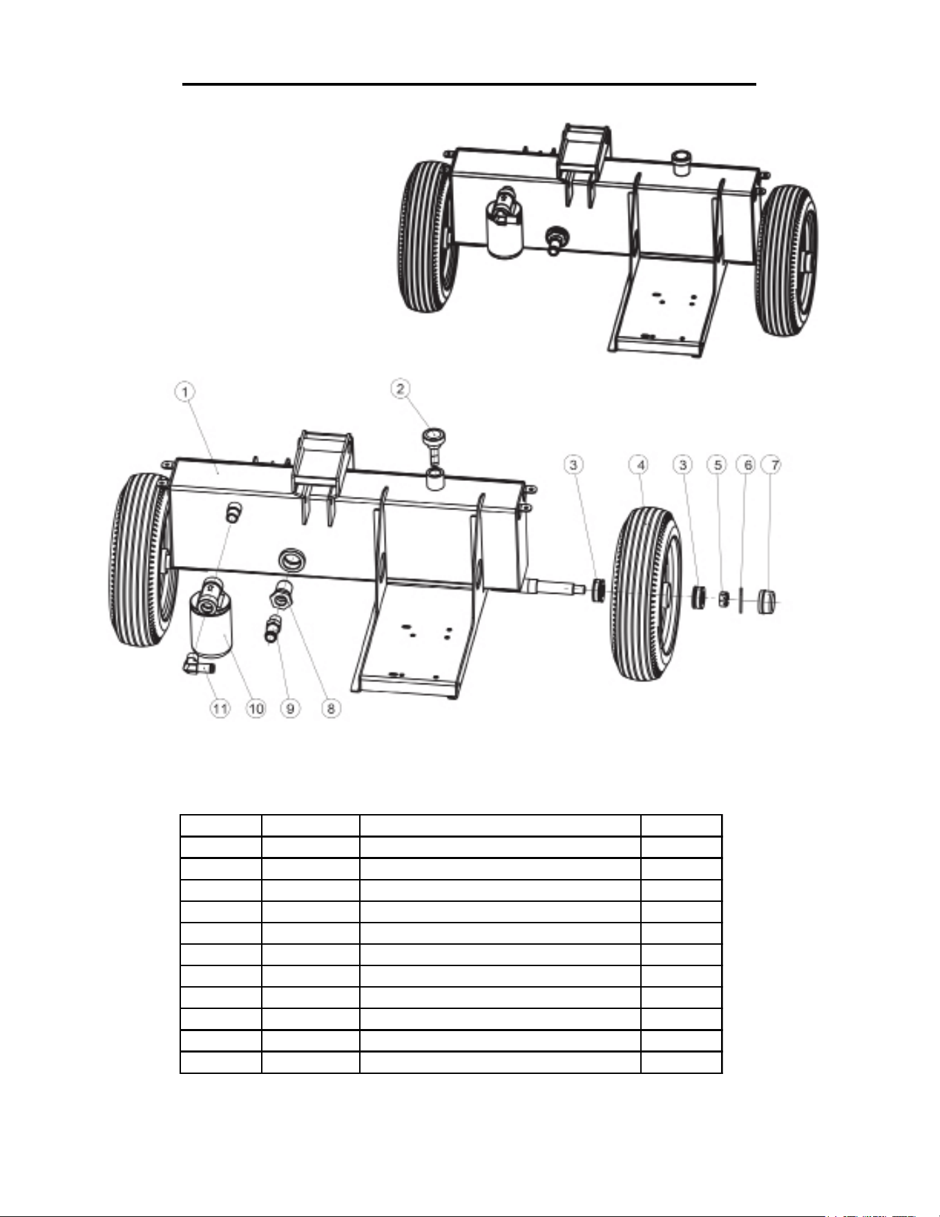
LOG SPLITTER EXPLODED VIEW AND PARTS LIST
HYDRAULIC TANK & TIRE ASSEMBLY
37
ITEM STOCK # DESCRIPTION QTY
1 56222-0301 TANK 1
2 56222-0302 VENT CAP ASSEMBLY 1
3 56222-0303 FLAT WASHER 2
4 56222-0304 TIRE ASSEMBLY 4.8X 8 2
5 56222-0305 NUT 2
6 56222-0306 COTTER PIN 2
7 56222-0307 HUB CAP 2
8 56222-0308 SUCTION STRAINER 1
9 56222-0309 SUCTION FITTING 1
10 56222-0310 RETURN LINE FITTER ASSEMBLY 1
11 56222-0311 RETURN LINE ELBOW FITTING 1
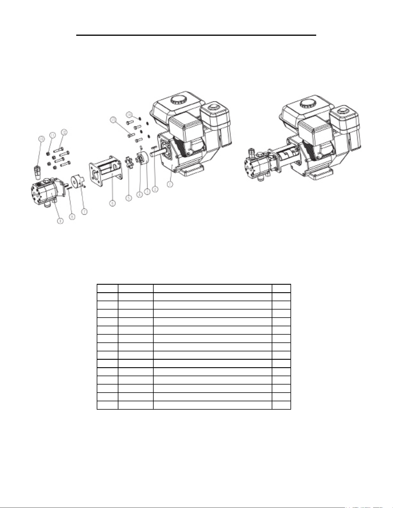
LOG SPLITTER EXPLODED VIEW AND PARTS LIST
ENGINE & PUMP ASSEMBLY
38
ITEM STOCK# DESCRIPTION QTY
1 56222-0401 ENGINE 1
2 56222-0402 BAR, KEY STOCK FOR ENGINE 1
3 56222-0403 JAW COUPLER 3/4-INCH BORE 1
4 56222-0404 SET SCREW M6X12 2
5 56222-0405 JAW SPIDER COUPLER 1
6 56222-0406 PUMP MOUNT 1
7 56222-0407 JAW COUPLER, 1/2-INCH BORE 1
8 56222-0408 BAR, KEY STOCK FOR PUMP 1
9 56227-0409 PUMP 2 STAGE 12 GPM 1
10 56222-0410 HIGH PRESSURE FITTING FOR PUMP 1
11 56222-0411 NUT M8 4
12 56222-0412 BOLT M8 X 30 4
13 56222-0413 BOLT 4
14 56222-0414 WASHER M8 4

39
WARRANTY STATEMENT
Remember to save the receipt and to accurately fill out and mail the product registration card. Proof of purchase
is required for all warranty work.
WEN® Log Splitters are under warranty to be free from defects in materials and workmanship for a period of
two (2) years from date of original purchase. Log Splitters used for Commercial or Rental use have a warranty
period of 90 days from date of original purchase. Keep purchase receipt and mail in the product registration card
for proof of purchase.
WEN® will repair or replace, at its discretion, any part that is proven to be defective in materials or workman-
ship under normal use during the two (2) years warranty period. Warranty repairs or replacements will be made
without charge for parts or labor. Parts replaced during warranty repairs will be considered as part of the original
product and will have the same warranty period as the original product.
To exercise the warranty, DO NOT RETURN TO RETAILER. Instead, call the toll free Customer Service
number at (800) 232-1195 and you will be instructed on where to take the log splitter for warranty service. Take
the log splitter and proof of purchase (the receipt) to the repair facility recommended by the Customer Service
Representative. To make a claim under this Limited Warranty, you must make sure to keep a copy of your proof
of purchase that clearly defines the Date of Purchase (month and year) and the Place of Purchase. Place of pur-
chase must be a direct vendor of Great Lakes Technologies, LLC. Third party vendors such as garage sales, pawn
shops, resale shops, or any other secondhand merchant void the warranty included with this product. Contact
[email protected] or 1-800-232-1195 to make arrangements for repairs and transportation.
When returning a product for warranty service, the shipping charges must be prepaid by the purchaser. The prod-
uct must be shipped in its original container (or an equivalent), properly packed to withstand the hazards of ship-
ment. The product must be fully insured with a copy of the warranty card and/or the proof of purchase enclosed.
There must also be a description of the problem in order to help our repairs department diagnose and fix the
issue. Repairs will be made and the product will be returned and shipped back to the purchaser at no charge.
THIS LIMITED WARRANTY DOES NOT APPLY TO ACCESSORY ITEMS THAT WEAR OUT FROM
REGULAR USAGE OVER TIME INCLUDING BELTS, BRUSHES, BLADES, ETC.
The warranty does not extend to log splitters damaged or affected by fuel contamination, accidents, neglect, mis-
use, unauthorized alterations, use in an application for which the product was not designed and any other modifi-
cations or abuse.
WEN® is not liable for any indirect, incidental or consequential damages from the sale or use of this product.
Any implied warranties are limited to two (2) years as stated in this written limited warranty. Some states do not al-
low the exclusion or limitation of incidental or consequential damages. Some states do not allow limitation on the
length of an implied warranty. This warranty gives you specific legal rights, and you may have other rights that vary
from state to state.

Thanks for remembering
