Owner's Manual
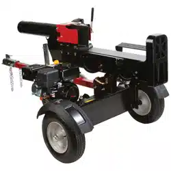
33 Ton Hydraulic
Log Splitter
Model Nos.
247.794520
CAUTION: Before
using this product,
read this manual and
follow all safety rules
and operating
instructions.
• Safety
• Assembly
• Operation
• Service
• Maintenance
• Espa5ol
Sears, Roebuck And Co., Hoffman Estates, IL 60179, U.S.A.
Printed in U.S.A. 770-10032A
(8/99)
Content Page
Warranty Information......................................... 2
Safe Operation Practices................................... 3
Accessories ....................................................... 6
Assembly ........................................................... 7
Operation ........................................................... 9
Maintenance ...................................................... 13
Content Page
Service & Adjustment ........................................ 15
Off-Season Storage ........................................... 17
Trouble-Shooting ............................................... 18
Parts List............................................................ 20
Espanbl ............................................................. 27
ONE-YEAR WARRANTY ON CRAFTSMAN LOG SPLITTER
For one year from the date of purchase, when this Craftsman log splitter is maintained, lubricated, and tuned up
according to the operating and maintenance instructions in the operator's manual, Sears will repair, free of
charge, any defect in material or workmanship.
This warranty excludes the tires, spark plug, oil filter and air cleaner, which are expendable parts and become
worn during normal use.
If this log splitter is used for commercial or rental purposes, this warranty applies for only 30 days from the date
of purchase.
Warranty service is available by contacting the nearest Sears service center in the United States. This warranty
applies only while this product is in use in the United States.
This warranty gives you specific legal rights, and you may also have other rights which vary from state to state.
Sears, Roebuck And Co., DEPT. 817WA, Hoffman Estates, IL 60179
Horsepower: ......................... 9
Engine Oil .............................. SAE 30/26 ounces
Fuel Capacity: ....................... Unleaded/1 gallon
Hydraulic Fluid ...................... Dexron III/7 gallons
Tire Pressure ......................... 30 p.s.i, max.
Spark Plug (Gap .030") .......... Champion RJ19LM
Model Number 247.794520
Serial Number ...........................................................
Date of Purchase ......................................................
Record model number, serial number and date of
purchase of the log splitter and keep in a safe place
for future reference.
2
This symbol points out important safety instructions which, if not followed, could endanger the per-
sonal safety and/or property of yourself and others. Read and follow all instructions in this manual before
attempting to operate your log splitter. Failure to comply with these instructions may result in personal injury.
When you see this symbol--heed its warning.
,_ DANGER:
Your leg splitter was built to be operated according to the rules for safe operation in this
manual. As with any type of power equipment, carelessness or error on the part of the oper-
ator can result in serious injury. If you violate any of these rules, you may cause serious
injury to yourself or others.
The engine exhaust from this product contains chemicals known to the state of California to cause
cancer, birth defects or other reproductive harm.
Towing
• This unit should not be towed on any street,
highwayor public road withoutchecking the
existingfederal, local or state requirements.
Such informationmay be obtained by callingyour
state or local bureau of motorvehicles. Any
licensingor modificationsneeded to comply with
federal, local or state vehicle requirements is the
sole responsibilityof the purchaser.*
• Make sure you followthe wiring diagram color
codes when installing the light kit on the log
splitter. (e.g. ground to ground, left turn to left
turn, etc.). Failure to wire unit correctly may
cause the tow vehicle wiring to overheat and/or
the log splitter lights to operate incorrectly, it may
be necessary to replace the turn signal flasher
unit in your tow vehicle if it is not capable of
operating the additional lights on the log splitter.
• Before towing the log splitteron a street, highway
or public road, vedfy that all lights are functioning
properly and the yellow side reflectors are in
position. Replace bulbs if they are burnt out.
• Before towing, always check to be certain the log
splitter is correctly and securely attached to the
tow vehicle, and safety chains are in place.
Leave slack in chains for turning allowance.
Use a class I or higher hitch with a 1-7/8" ball.
Keep ball socket and clamp face lubricated with
chassis grease.
• Be sure the coupler is secured to the hitch ball
and the lock lever is down tight and locked.
Check vehicle hitch, ball and coupler for signs of
wear or damage. Replace any parts that are worn
or damaged before towing.
• The coupler must be secured to the log splitter
tongue tube with the original equipment bolts and
nuts. See your authorized service dealer for
replacement parts. Coupler nuts should be
tightened securely (20 foot pounds).
• Make sure beam assembly is securely latched in
the horizontal position and jack stand (if provided)
is pivoted and secured in the up position before
towing log splitter. Never tow with the beam in
vertical position.
• Do not tow the log splitter faster than 45 MPH.
Higher speeds may damage log splitter.
Excessive high speeds may cause the log splitter
to "fishtail" or otherwise become unstable.
• Check the tire pressure on the log splitter tires. It
should not exceed 30 p.s.i, for highway travel.
• When parking, storing or using your log splitter,
keep the coupler off the ground so dirt will not
build up in the ball socket.
• Do not allow anyone to sit or ride on your log
splitter. They can easily fall off and be seriously
injured.
Training
• Before operatingthis logsplitter, read and
understandthis operator's manual completely.
Become familiarwith itfor your ownsafety. To fail
to do so may cause serious injury.Do not allow
anyone to operate your log splitterwho has not
read this manual. Keep this manual in a safe
place forfuture and regular reference and for
ordering replacement parts.
Never use your splitterfor any other purpose than
splittingwood. It is designed for this use and any
other use may cause an injury.Your log splitteris
a precisionpiece of power equipment, not a toy.
Therefore, exercise extreme caution at all times.
• Never allow childrento operate your log splitter.
Do not allow adults to operate it withoutproper
instruction.Only personswell acquainted with
these rules of safe operationshould be allowed to
use your logsplitter.
Only the operator is to be near your log splitter
during use. Keep all others, includingpets and
children, a minimum of 20 feet away from your
work zone. Flyingwood can be hazardous. If a
helper is assistingin loadinglogs, never activate
3
the control until the helper is clear of the area,
More accidents occur when more than one
person operates the log splitter than at any other
time,
No one should operate this unit while intoxicated
or while taking medication that impairs the
senses or reactions. A clear mind is essential for
safety. Never allow a person who is tired or
otherwise not alert to use your log splitter.
Preparation
• Never wear loose clothingor jewelry that can be
caught by moving parts of your log splitterand
pullyou intoit, Keep clothingaway from all
moving parts of your log splitter.
• Wear proper head gear to keep hair away from
moving parts. Always wear protective hearing
devices as needed.
• Always wear safety shoes. A dropped log can
seriously injure your foot.
• Always wear safety glasses or goggles while
operating your splitter. A piece of splittinglog
could fly off and hit your eyes.
• Wear leather work gloves. Be sure they are tight
fitting without loose cuffs or draw strings.
• Use your log splitter in daylight, or under good
artificial light.
• Never operate your splitter on slippery, wet,
muddy or icy surfaces. Safe footing is essential
in preventing accidents.
• Never operate your splitter while attached to a
towing vehicle.
Only operate your splitter on level ground and
not on the side of a hill. It could tip, or rolling logs
or poor footing could cause an accident.
Operating the splitter on level ground also
prevents the spillage of gasoline from the fuel
tank.
• Never attempt to move the log splitterover hilly
or uneven terrain without a tow vehicle or
adequate help,
• Always block the wheels to prevent movement
of log splitter while in operation.
• Check the fuel before starting the engine.
Gasoline is an extremely flammable fuel. Do not
fill the gasoline tank indoors, when the engine is
running, or while the engine is still hot. Replace
gasoline cap securely and wipe off any spilled
gasoline before starting the engine as it may
cause a fire or explosion.
Both ends of each log must be cut as square as
possible to help prevent the log from riding out of
the splitter duringoperation.
Operation
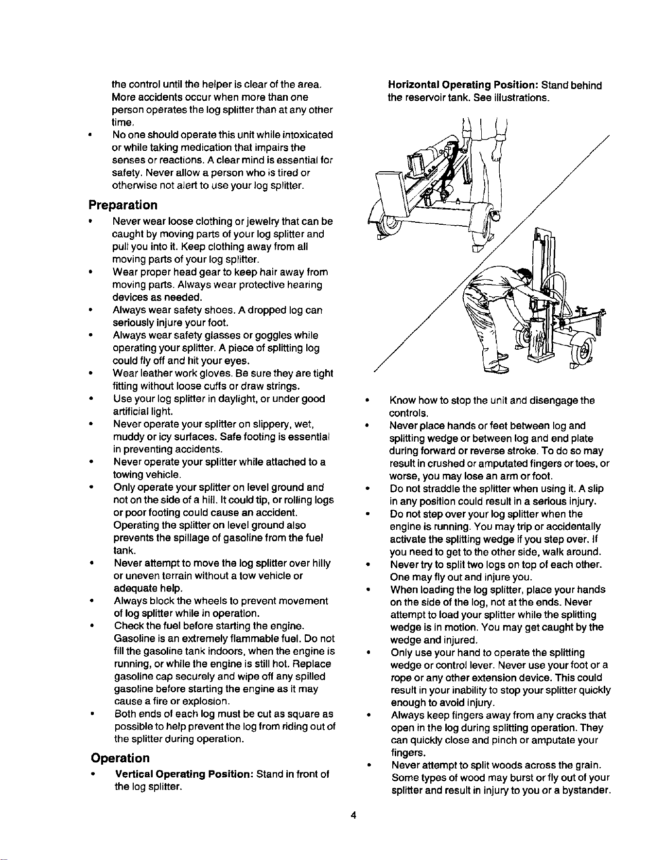
Vertical Operating Position: Stand in front of
the log splitter.
Horizontal Operating Position: Stand behind
the reservoir tank. See illustrations.
Know how to stopthe unit and disengage the
controls.
Never place hands or feet between log and
splitting wedge or between log and end plate
during forward or reverse stroke. To do so may
result in crushedor amputated fingers or toes, or
worse, you may lose an arm or foot.
Do not straddle the splitterwhen using it. A slip
in any position could result in a serious injury.
Do not step over your log splitter when the
engine is running. You may trip or accidentally
activate the splittingwedge if you step over. If
you need to get to the other side, walk around.
Never try to splittwo logs on top of each other.
One may fly out and injure you.
When loading the log splitter, place your hands
on the side of the log, not at the ends. Never
attempt to load your splitter while the splitting
wedge is in motion. You may get caught by the
wedge and injured.
Only use your hand to operate the splitting
wedge or control lever. Never use your foot or a
rope or any other extension device. This could
result in your inability to stop your splitter quickly
enough to avoid injury.
Always keep fingers away from any cracks that
open in the log during splitting operation. They
can quickly close and pinch or amputate your
fingers.
Never attempt to split woods across the grain.
Some types of wood may burst or fly out of your
splitter and result in injury to you or a bystander.
4
For logs that are not cut square, the longest
portion of the log should be rotated down and
the most square end placed against the splitting
wedge.
Keep your work area clean. Immediately
remove splitwood around your splitterso that
you do not stumble over it.Clean chips and dirt
off end plate (wood platform) after each log is
split,or whenever necessary to maintainflat
contact between wood and end plate (platform).
Never move the log splitterwhile the engine is
running.
Never leave your log splitterunattended withthe
engine running.Shut off the engine if you are
leaving your splitter, even for a short period of
time. Someone could accidentally activate the
splittingwedge and be injured.
Do not run engine inan enclosed area. Exhaust
gases containcarbon monoxide. This odorless
gas can be deadly when inhaled.
Be careful notto touch the muffler after the
engine has been running. It will be HOT!
Ifthe equipment should start to vibrate
abnormally, stop the engine and check
immediatelyfor the cause. Vibration is generally
a warning of trouble.
When cleaning, repairing or inspecting, make
certain all moving parts have stopped.
Disconnect the spark plug wire and keep the
wire away from the plugto prevent accidental
starting.
Customer Responsibilities
• Do not operate your splitter in poor mechanical
conditionor when in need of repair.
• Periodicallycheck that all nuts, bolts,screws,
hose clamps and hydraulicfittingsare tight to be
sure equipment is insafe working condition.
Where appropriate, check allsafety guards and
shieldsto be sure they are inthe proper position.
Never operate your splitterwith safety guards,
shields orother protective features removed.
These safetydevices are for your protection.
• Replace all damaged or worn partssuch as
hydraulichoses and fittings immediately with
manufacturer approved replacement parts.
• Do notchange the engine governorsettings or
overspeed the engine. This increases the
hazard of personal injury.The maximum engine
speed is preset by the manufacturer and is
withinsafety limits.
• Do not alter your tog splitter in any manner such
as attaching a rope or extension to the control
lever or adding to the width or height of the
wedge. Such alterations may cause your splitter
to be unsafe.
5
• Perform all recommended maintenance
procedures before you use your splitter.
• Do not serviceor repairyour log splitterwithout
disconnectingthe spark plugwire and moving it
away from the spark plug.
Never storethe equipment with gasoline in the
tank insideof a buildingwhere ignitionsources
are present, such as hotwater and space
heaters, clothes dryers and the like. Allow the
engine to cool before storing inany enclosure.
Always store gasoline in an approved, tightly
sealed container. Store the container in a cool,
dry place. Do notstore in a building where
ignitionsources are present.
• To reduce fire hazard, keep engine free of grass,
leaves, wood chips, and excessive grease and
oil.
The hydraulic system of your log splitter requires
careful inspection, along with the mechanical
parts. Be sure to replace frayed, kinked, or
otherwise damaged hydraulic components.
• Fluid escaping from a very small hole can be
almost invisible. Do not check for leaks with your
hand. Escaping fluid under pressure can have
sufficient force to penetrate skin, causing
serious personal injury. Leaks can be located by
passing a piece of cardboard or wood over the
suspected leak and looking for discoloration.
• Should it become necessary to loosen or
remove any hydraulic fitting or line, be sure to
relieve all pressure by shuttingoff the engine
and moving the control handle back and forth
several times.
Do not remove the cap from the hydraulic tank or
reservoir while your log splitteris running. Hot oil
under pressure could cause injury.
• The pressure relief valve on your splitter is
preset at the factory. Do not adjust the valve.
Only a qualified service technician should
perform this adjustment.
• Completely drain fuel tank prior to storage. This
guards against accumulation of fuel fumes
which could result in a fire hazard.
• Never store log splitter outside without a
waterproof cover. Rain will cause rust on the
inside of the cylinder.
Important Information
Always:
Use clean fluidand check fluid level regularly
• Use Dexron Ill AutomaticTransmission Fluid or
lOW non-foaming hydraulic fluid.
• Use a filter (clean or replace regularly)
• Use a breather cap on fluid reservoir
Make certain pump is mounted and aligned
properly
Use a flexible "spider" type coupling between
engine and pump drive shafts
Keep hoses clear and unblocked
Bleed air out of hoses before operating
Flush and clean hydraulic system before start-
up after any malfunction or servicing
Use "pipe dope" on all hydraulic fittings
Allow time for warm-up before splitting wood •
Prime the pump before initial start-up by turning
over the engine with spark plug disconnected
• Split wood with the grain (lengthwise) only
Never:
• Use when fluid is below 20+F, or above 150 ° F.
• Use a solid engine/pump coupling
Force pump when mounting
• Operate through relief valve for several seconds
Attempt to adjust unloading or relief valve
settings without pressure gauges
• Operate with air in hydraulic system
Use Teflon tape on hydraulic fittings
• Attempt to cut wood across the grain.
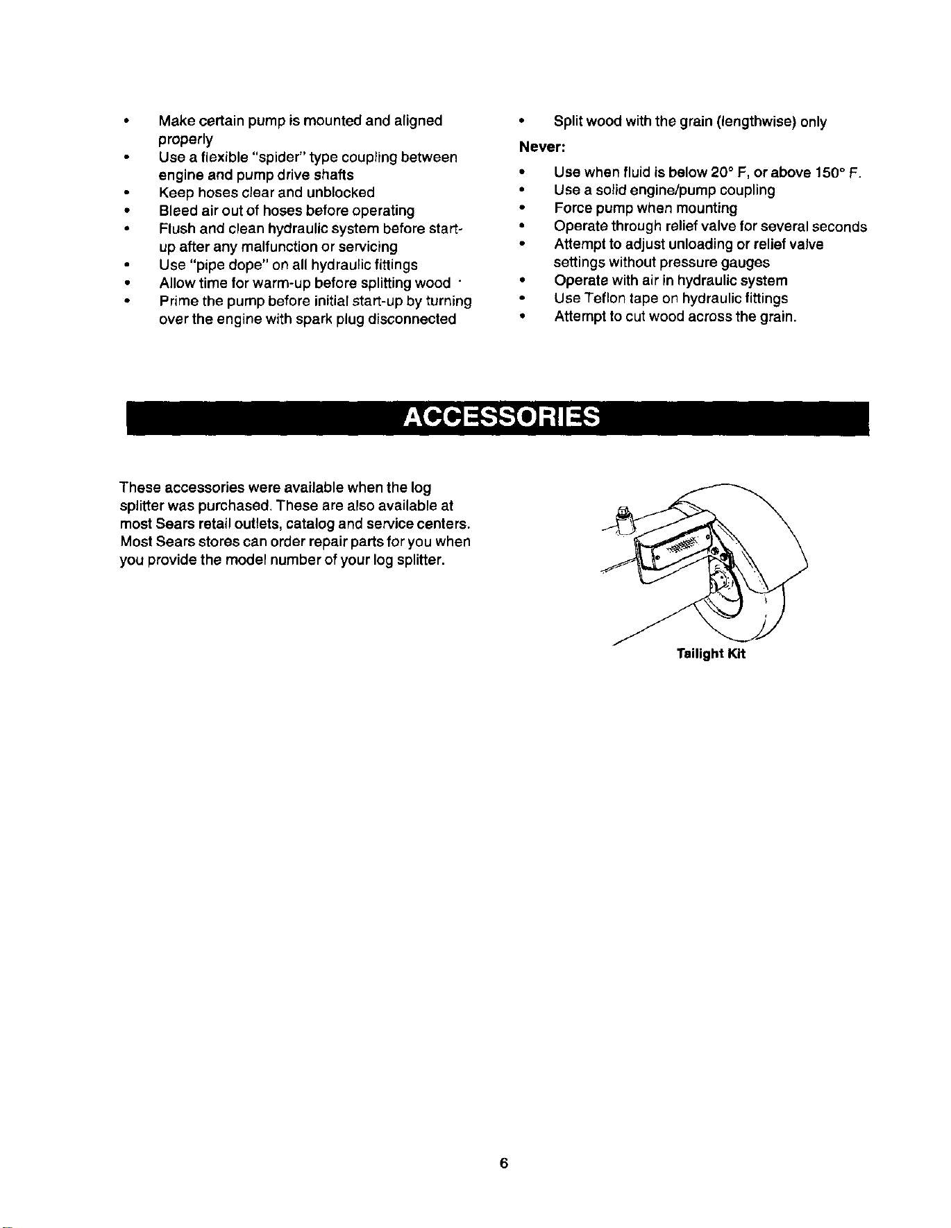
These accessories were available when the log
splitterwas purchased. These are also available at
most Sears retail outlets, catalog and service centers.
Most Sears stores can order repair parts for you when
you provide the model number of your log splitter.
Tailight Kit
6
IMPORTANT: This unitis shipped without gasoline
in the engine. After assembly, see OPERATION
section of thismanual for proper fuel fill-up.
Tools and Other Items Required
Crowbar or large screwdriver
A pair of 9/16" or adjustable wrenches*
Screwdriver
Cutters
Engine oil
Unleaded gasoline
Dexron III automatic transmission fluid or 10W non-
foaming hydraulic fluid (approximately 7 gallons)
Unpacking from Crate
WARNING: Exercise extreme caution as
parts are very heavy. Mechanical handling
equipment orsufficientmanpower should
be used to prevent injury.
• Pry the top, sidesand ends offcrate using a
crowbar or large screwdriver.
• Set panels aside to avoid tire puncturesor
personal injury.
• Remove and discard plastic bag that covers
unit.
Note: Do not remove the banding fromaround the
tank until the log splitteris assembled.
Disconnecting Spark Plug
• Before you startthe assembly procedure,
disconnect the spark plug wire fromthe spark
plug on the leg splitterengine and move the wire
away from the spark plug. This will prevent
accidental starting. See Figure 1.
Disconnectspark
plug
Figure I
Setting Up Log Splitter
NOTE: Afthardware needed forassembling your
Craftsman log splitter has been placed in positionon
the equipment.
7
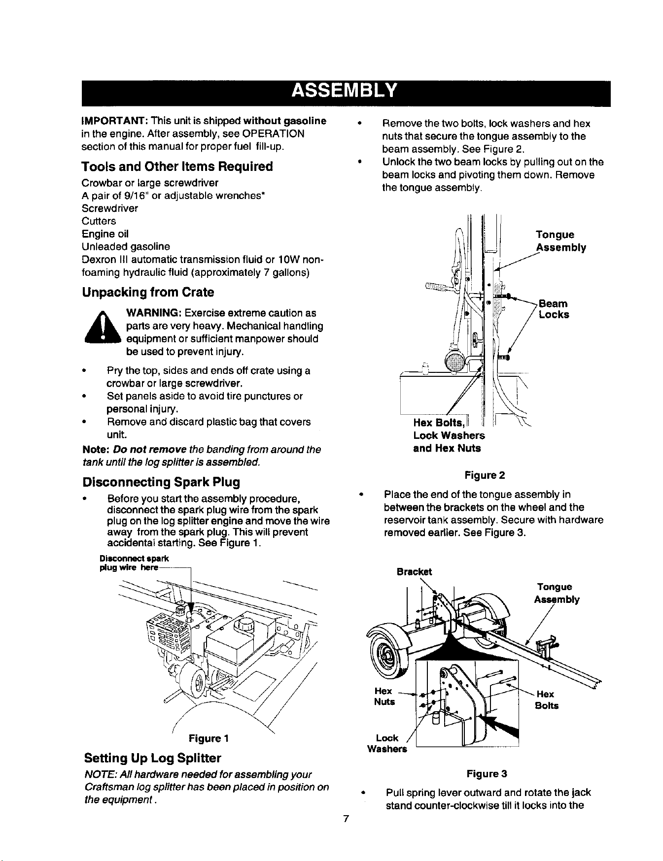
• Remove the two bolts, lock washers and hex
nuts that secure the tongue assembly to the
beam assembly, See Figure 2.
• Unlock the two beam locks by pulling out on the
beam locks and pivoting them down. Remove
the tongue assembly.
Tongue
Assembly
,Beam
I
Hex Bolts,
Lock Washers
and Hex Nuts
Figure 2
Place the end of the tongue assembly in
between the brackets on the wheel and the
reservoir tank assembly. Secure with hardware
removed earlier. See Figure 3.
Bracket
Tongue
Assembly
Hex
Bolts
Lock
Washers
Figure 3
Pull spring lever outward and rotate the jack
stand counter-clockwise till it locks into the
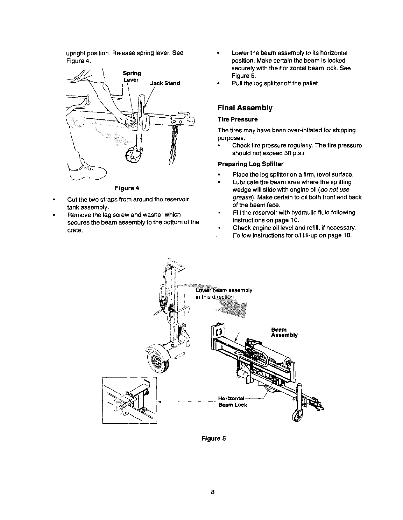
uprightposition.Releasespringlever. See
Figure 4,
Spring
Lever
Jack Stand
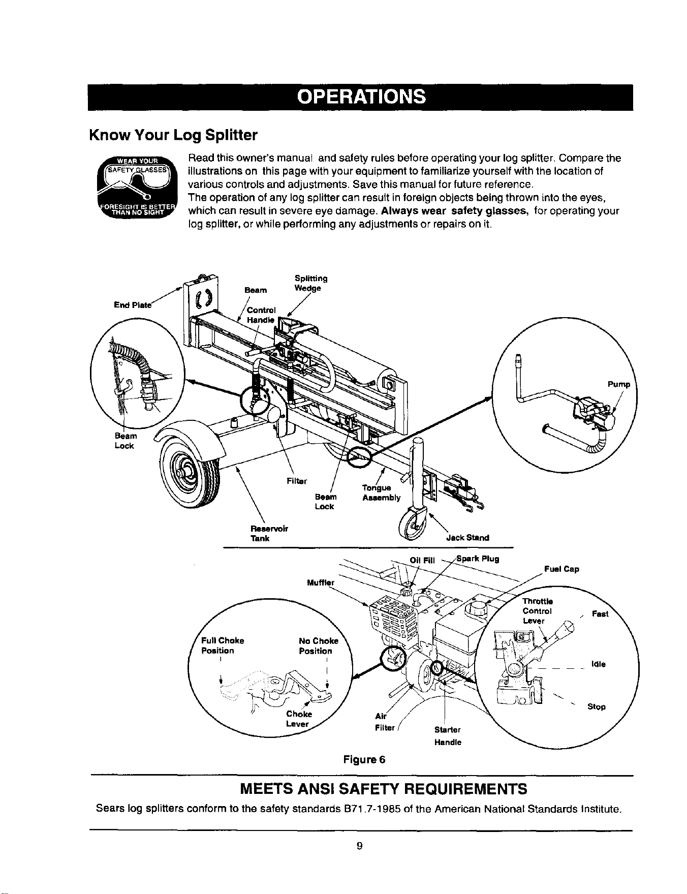
Lower the beam assemblyto its horizontal
position. Make certain the beam is locked
securely withthe horizontalbeam lock. See
Figure 5.
Pull the log splitteroff the pallet.
Figure 4
Cut the two straps from around the reservoir
tank assembly,
Remove the lag screw and washer which
secures the beam assembly to the bottom of the
crate.
Final Assembly
Tire Pressure
The tires may have been over-inflated for shipping
purposes.
• Check tire pressure regularly. The tire pressure
should not exceed 30 p.s.i.
Preparing Log Splitter
Place the logsplitteron a firm, level surface.
Lubricate the beam area where the splitting
wedge will slide with engine oil (do not use
grease). Make certain to oil both front and back
of the beam face.
Fill the reservoir with hydraulic fluid following
instructions on page 10.
Check engine oil level and refill, if necessary.
Follow instructions for oil fill-up on page 10.
Beam
Assembly
Horizontal--
Beam Lock
Figure 5
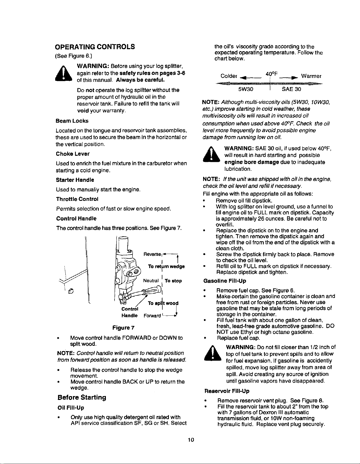
Know Your Log Splitter
Read this owner's manual and safety rules before operating your log splitter. Compare the
illustrations on this page with your equipment to familiarize yourself with the location of
various controls and adjustments. Save this manual for future reference.
The operation of any log splitter can result in foreign objects being thrown into the eyes,
which can result in severe eye damage. Always wear safety glasses, for operating your
log splitter, or while performing any adjustments or repairs on it.
Splitting
Beam yge
Beam
Lock
Filter
Reservoir
Tank
Beam
Lock
Muffler
011 Fill
Jack Stand
Fuel Cap
Filter Starter
Handle
Figure 6
MEETS ANSI SAFETY REQUIREMENTS
Sears log splitters conform to the safety standards B71.7-1985 of the American National Standards Institute.
9
OPERATING CONTROLS
(See Figure 6.)
WARNING: Before usingyour log splitter,
again referto the safety rules on pages 3-6
of this manual. Always be careful,
Do not operate the log splitterwithoutthe
proper amount of hydraulicoil inthe
reservoirtank. Failure to refillthe tank will
void your warranty.
Beam Locks
Located on the tongue and reservoir tank assemblies,
these are usedto secure the beam inthe horizontalor
the vertical position.
Choke Lever
Used to enrich the fuel mixture in the carburetor when
startinga cold engine.
Starter Handle
Used to manually start the engine.
Throttle Control
Permits selection of fast or slow engine speed.
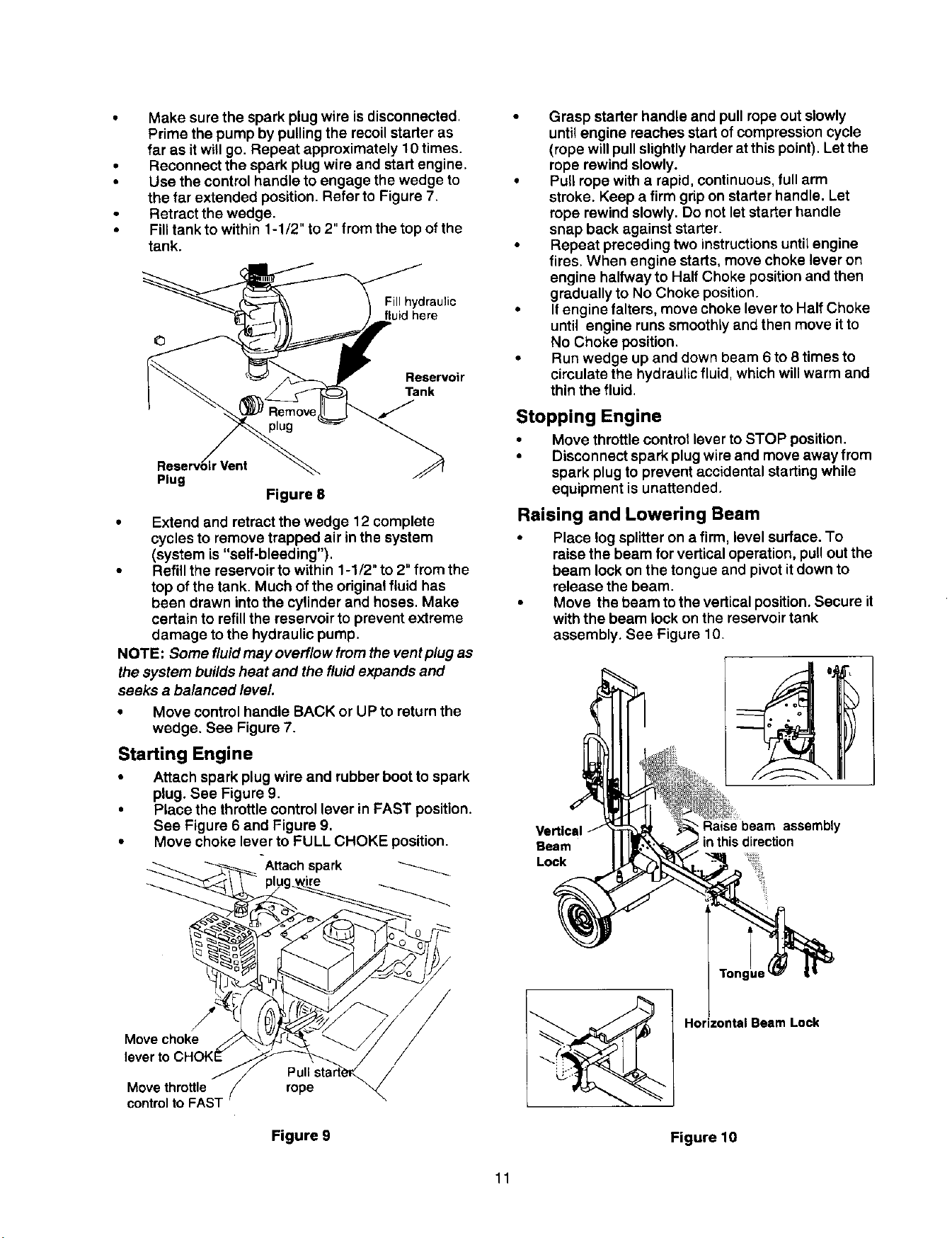
Control Handle
The control handle hasthree positions.See Figure7.
_" Neutral I To stop
/To ,p,tt,, od
Control I
Handle Forward L_._,.
Figure 7
• Move control handle FORWARD or DOWN to
spilt wood.
NOTE: Controlhandle will return to neutralposition
fromforward position as soon as handle is released.
Release the control handle to stop the wedge
movement.
• Move control handle BACK or UP to return the
wedge.
Before Starting
Oil Fill-Up
Only use high quality detergent oil rated with
APi service classification SF, SG or SH. Select
the oil's viscosity grade according to the
expected operating temperature. Follow the
chart below.
NOTE: Although multi-viscosity oils (514/30,10W30,
etc.) improve starting in cold weather, these
mu/tiviscosity oils will result in increased oil
consumption when used above 40°1:. Check the oi/
level more frequently to avoid possible engine
damage from running low on oil.
&
WARNING: SAE 30 oil, if used below 40°F,
will result in hard startingand possible
engine bore damage due to inadequate
lubrication.
NOTE: If the unit was shipped with oil in the engine,
check the oil level and refill ff necessary.
Fill engine with the appropriate oil as follows:
• Remove oil fill dipstick.
• With log splitter on level ground, use a funnel to
fill engine oil to FULL mark on dipstick. Capacity
is approximately 26 ounces. Be careful not to
overfill.
• Replace the dipstickonto the engine and
tighten. Then remove the dipstickagain and
wipe off the oilfrom the end of the dipstickwith a
clean cloth.
• Screw the dipstickfirmly back to place. Remove
to check the oil level.
Refill oil to FULL mark on dipstick if necessary.
Replace dipstickand tighten.
Gasoline Fill-Up
&
Remove fuel cap. See Figure 6.
Make certain the gasoline container isclean and
free from rustorforeign particles. Never use
gasoline that may be stale from long periods of
storage inthe container.
Fillfuel tank with about one gallon of clean,
fresh, lead-free grade automotive gasoline. DO
NOT use Ethyl or high octane gasoline.
Replace fuel cap.
WARNING: Do not fill closer than 1/2 inchof
top of fuel tank to prevent spillsand to allow
for fuel expansion. If gasoline is accidently
spilled, move log splitter away from area of
spill. Avoid creating any source of ignition
untilgasoline vapors have disappeared.
Reservoir Fill-Up
Remove reservoir vent plug. See Figure 8.
Fill the reservoir tank to about 2" fromthe top
with 7 gallons of Dexron III automatic
transmissionfluid, or 10W non-foaming
hydraulicfluid. Replace vent plug securely.
10
• Make sure the spark plug wire is disconnected.
Prime the pump by pulling the recoilstarter as
far as it will go. Repeat approximately 10 times.
• Reconnect the spark plug wire and start engine.
• Use the control handle to engage the wedge to
the far extended position. Refer to Figure 7.
Retract the wedge.
• Fill tank to within 1-1/2" to 2" from the top of the
tank.
Fill hydraulic
fluid here
Reservoir
Tank
Reservo_irVent
Plug
Figure 8
• Extend and retract the wedge 12 complete
cycles to remove trapped air in the system
(system is "self-bleeding").
• Refill the reservoir to within 1-1/2" to 2" from the
top of the tank. Much of the originalfluid has
been drawn intothe cylinder and hoses. Make
certain to refillthe reservoir to prevent extreme
damage to the hydraulicpump.
NOTE; Some fluidmay overflow from the ventplug as
the system builds heat and the fluidexpands and
seeks a balanced level.
Move control handle BACK or UP to returnthe
wedge. See Figure 7.
Starting Engine
• Attach spark plug wire and rubber boot to spark
plug. See Figure 9,
• Place the throttlecontrol lever in FAST position.
See Figure 6 and Figure 9,
• Move choke lever to FULL CHOKE position,
A_ach spark
• Grasp starter handle and pull rope out slowly
untilengine reaches start of compression cycle
(rope will pullslightlyharderat thispoint). Let the
rope rewindslowly.
• Pull rope with a rapid, continuous,full arm
stroke. Keep a firm gdp on starter handle. Let
rope rewind slowly. Do not let starter handle
snap back against starter.
• Repeat preceding two instructions until engine
fires. When engine starts, move choke lever on
engine halfway to Half Choke position and then
gradually to No Choke position.
• If engine falters, move choke lever to Half Choke
until engine runs smoothly and then move it to
No Choke position.
• Run wedge up and down beam 6 to 8 times to
circulate the hydraulic fluid, which will warm and
thin the fluid.
Stopping Engine
• Move throttlecontrol lever to STOP position.
• Disconnect sparkplug wireand move away from
spark plug to prevent accidental starting while
equipment is unattended.
Raising and Lowering Beam
• Place log splitteron a firm, level surface. To
raise the beam for vertical operation, pull out the
beam lock on the tongue and pivot it down to
release the beam.
• Move the beam to the verticalposition. Secure it
withthe beam lock on the reservoirtank
assembly. See Figure 10,
Beam
Lock
Raise beam assembly
inthis direction
Move choke
lever tc
/
Move throttle rope
control
Figure 9
/
Horizontal Beam Lock
Figure 10
11
Tolowerthe beam, pull outthe beam lock on the
reservoir tank and pivot it down to release the
beam. Carefully pull back on beam and lower it
to the horizontal position. See Figure 10.
Pull out the beam lock on the tongue, pivot it
upwards and release it to hold the beam. Make
certain it is latched securely.
WARNING: Always use the log splitterin the
vertical position only when splitting heavy
logs.
Transporting the Log Splitter
• Lower the beam to its horizontalposition. Make
certain the beam is locked securely withthe
horizontal beam lock.
Raise or lower jack stand to attach the hitch to a
towingvehicle, Make certain to latch securely.
Pull spring lever onjack stand outward and
rotate the jack stand clockwise till it is parallel
withthe tongue assembly. Release the spring
lever after it locksinto position.
• Attach the safety chains to the towing vehicle.
Operating Position
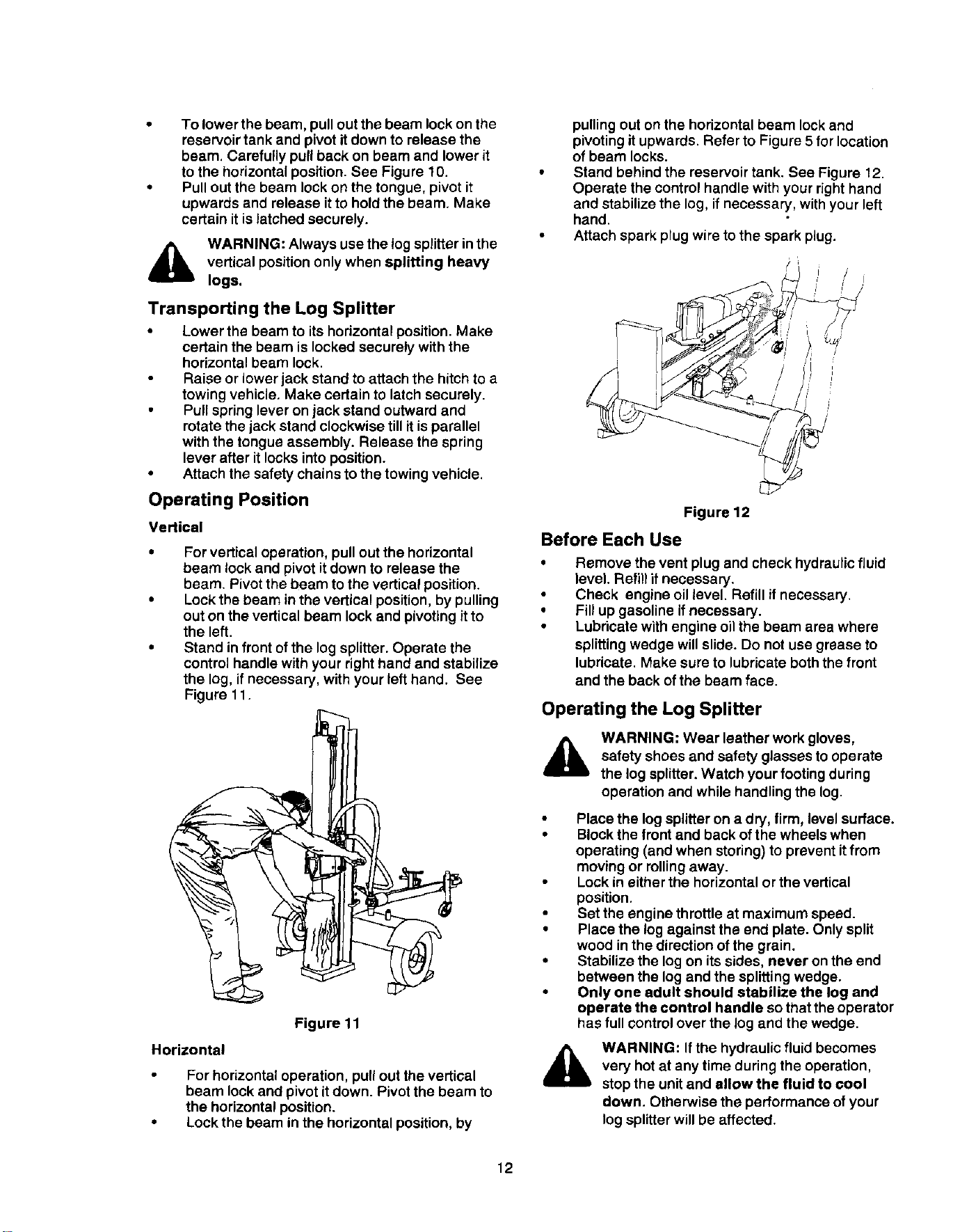
Vertical
• For vertical operation, pull out the horizontal
beam lock and pivot itdown to release the
beam. Pivotthe beam to the vertical position.
• Lockthe beam in the vertical position, by pulling
out on the vertical beam lock and pivoting itto
the left.
• Stand in front of the log splitter. Operate the
control handle with your right hand and stabilize
the log, if necessary, with your left hand. See
Figure 11.
Figure 11
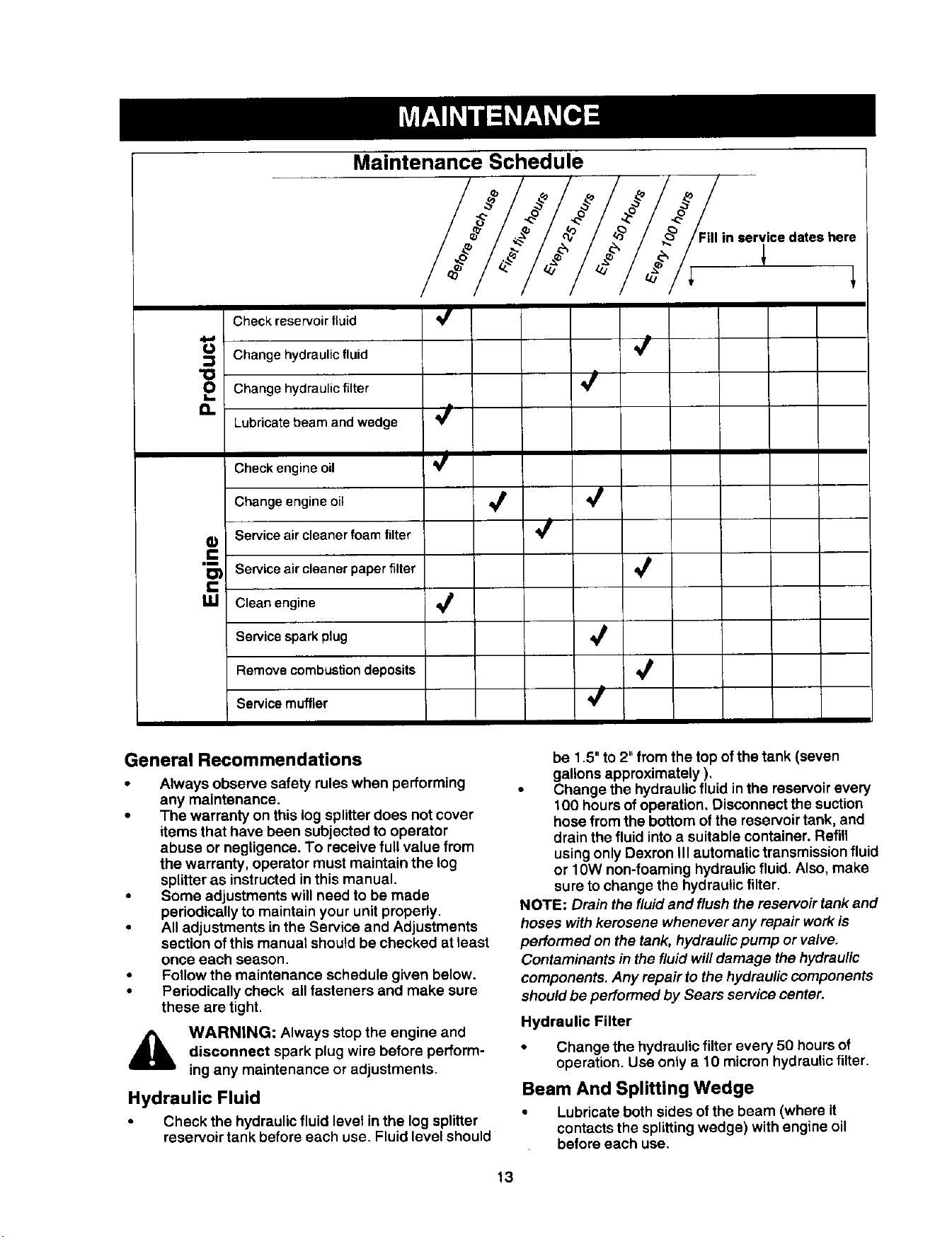
Horizontal
For horizontal operation, pullout the vertical
beam lock and pivot it down. Pivot the beam to
the horizontal position.
Lock the beam in the horizontal position, by
pulling out onthe horizontal beam lockand
pivoting it upwards. Refer to Figure 5 for location
of beam locks.
Stand behind the reservoir tank. See Figure 12.
Operate the control handle with your right hand
and stabilize the log, if necessary, with your left
hand.
Attach spark plug wire to the spark plug.
_ i /
L7
Figure 12
Before Each Use
• Remove the vent plug and check hydraulicfluid
level. Refill if necessary.
• Check engine oil level. Refill if necessary.
• Fill up gasoline if necessary.
• Lubricate with engine oil the beam area where
splitting wedge will slide. Do not use grease to
lubricate. Make sure to lubricate both the front
and the back of the beam face.
Operating the Log Splitter
A
WARNING: Wear leather work gloves,
safety shoes and safety glasses to operate
the log splitter.Watch your footing during
operation and while handling the log.
Place the log splitter on a dry, firm, level surface.
Block the front and back of the wheels when
operating (and when storing) to prevent it from
moving or rolling away.
Lock in either the horizontal or the vertical
position,
Set the engine throttle at maximum speed.
Place the log against the end plate. Only split
wood in the direction of the grain.
Stabilize the log on its sides, never on the end
between the log and the splitting wedge.
Only one adult should stabilize the log and
operate the control handle so that the operator
has full control over the log and the wedge.
WARNING: If the hydraulic fluid becomes
very hot at any time during the operation,
stop the unit and allow the fluid to cool
down. Otherwise the performance of your
log splitterwill be affected.
12
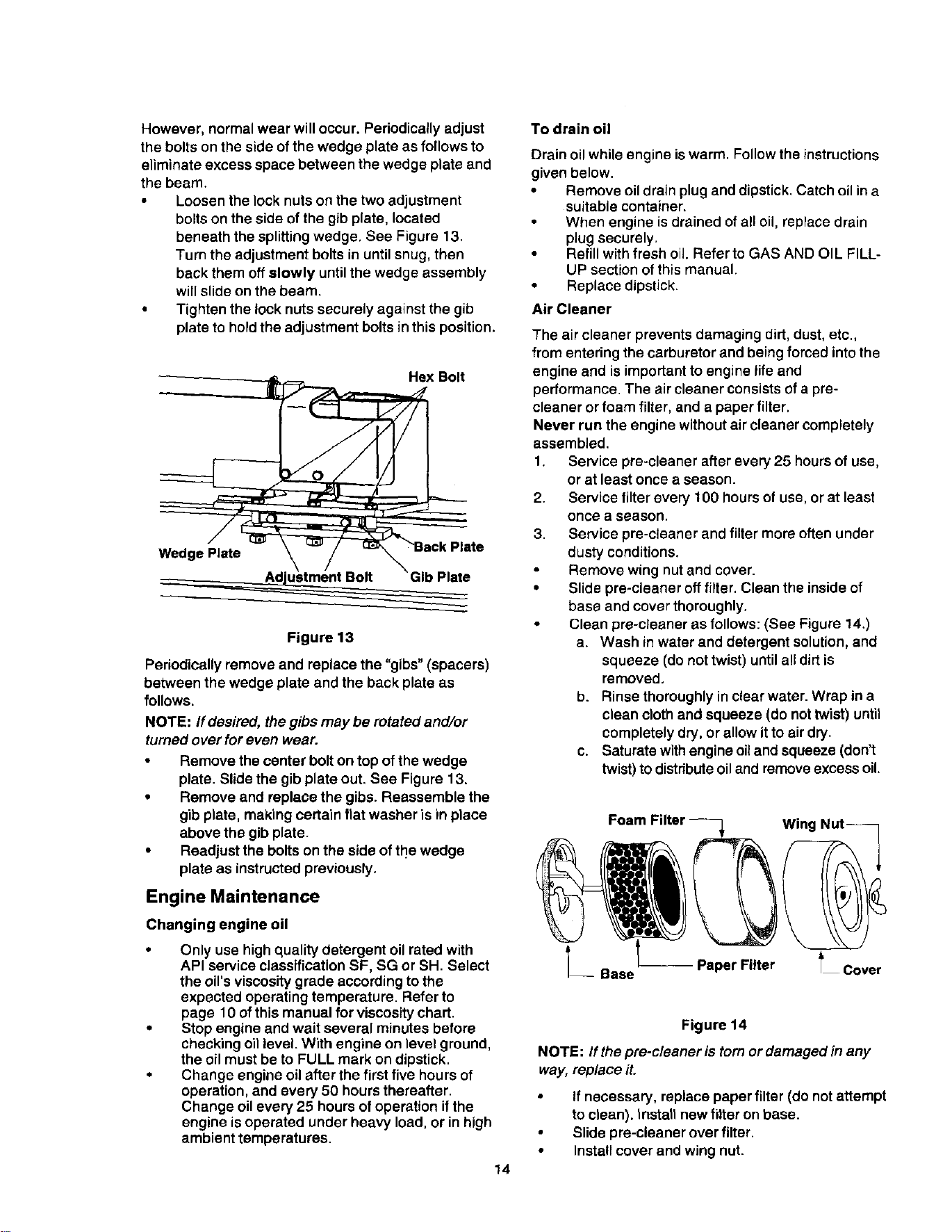
Maintenance Schedule
//Fill in servicedates here
Check reservoir fluid
" 4
0 Changehydraulicfluid
"_ Change hydraulicfilter
a. Lubricatebeam and wedge
Checkengine oil
Changeengineoil _
W Serviceaircleanerfoam filter
"--
I_ Serviceair cleanerpaperfilter
C
g..I Clean engine
Servicesparkplug
Removecombustiondeposits
Servicemuffler
General Recommendations
• Always observe safety rules when performing
any maintenance.
• The warranty on this log splitterdoes not cover
items that have been subjected to operator
abuse or negligence. To receive full value from
the warranty, operator must maintain the log
splitteras instructedin this manual•
• Some adjustments will need to be made
periodicallyto maintain your unit propedy.
• All adjustments in the Service and Adjustments
section of thismanual should be checked at least
once each season•
• Follow the maintenance schedule given below.
• Periodically check all fasteners and make sure
these are tight•
,_ WARNING: Always stop the engine and
disconnect spark plug wire before perform-
ing any maintenance or adjustments•
Hydraulic Fluid
Check the hydraulicfluid level in the log splitter
reservoir tank before each use. Fluid level should
be 1.5" to 2" from the top of the tank (seven
gallons approximately ).
• Change the hydraulic fluid in the reservoirevery
100 hoursof operation. Disconnect the suction
hosefrom the bottom of the reservoirtank, and
drainthe fluid into a suitable container. Refill
usingonly Dexron III automatic transmissionfluid
or 10W non-foaming hydraulicfluid. Also, make
sure to change the hydraulicfilter•
NOTE: Drain the fluidand flush the reservoir tank and
hoses withkerosene whenever any repair work is
performed on the tank, hydraulic pump or valve.
Contaminants in the fluid will damage the hydraulic
components.Any repair to the hydrauliccomponents
should be performed by Sears service center.
Hydraulic Filter
Change the hydraulicfilter every 50 hoursof
operation. Use only a t 0 micron hydraulicfilter•
Beam And Splitting Wedge
Lubricate both sides of the beam (where it
contactsthe splittingwedge) withengine oil
before each use,
13
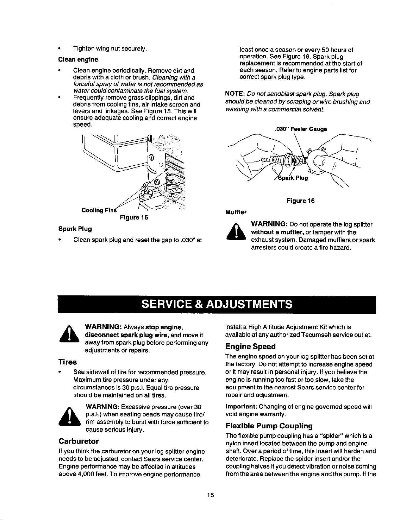
However, normalwear will occur. Periodically adjust
the bolts on the side of the wedge plate as follows to
eliminate excess space between the wedge plate and
the beam.
Loosen the lock nuts on the two adjustment
boltson the side of the gib plate, located
beneath the splitting wedge. See Figure 13.
Turn the adjustment bolts in until snug, then
back them off slowly untilthe wedge assembly
willslide on the beam.
• Tighten the lock nutssecurely against the gib
plate to hold the adjustment bolts in this position,
-_ Hex Bolt
Figure 13
Periodically remove and replace the "gibs" (spacers)
between the wedge plate and the back plate as
follows.
NOTE: If desired, the gibs maybe rotated and/or
turned over for even wear.
Remove the center bolt on top of the wedge
plate. Slide the gib plate out, See Figure 13.
Remove and replace the gibs. Reassemble the
gib plate, making certain flat washer is in place
above the gib plate.
Readjust the bolts on the side of tl_ewedge
plate as instructedpreviously.
Engine Maintenance
Changing engine oil
• Only use high quality detergent oil rated with
API service classification SF, SG or SH. Select
the oil's viscosity grade according to the
expected operatingtemperature. Refer to
page 10 of this manual for viscositychart.
• Stop engine and wait several minutes before
checking oil level. With engine on level ground,
the oil must be to FULL mark on dipstick.
• Change engine oil after the first five hours of
operation, and every 50 hoursthereafter.
Change oil every 25 hours of operation if the
engine is operated under heavy load, or in high
ambient temperatures.
14
To drain oil
Drain oil while engine is warm. Follow the instructions
given below.
• Remove oildrain plug and dipstick. Catch oil ina
suitable container.
• When engine is drained of all oil, replace drain
plugsecurely.
Refillwith fresh oil. Refer to GAS AND OIL FILL-
UP section of this manual.
• Replace dipstick.
Air Cleaner
The air cleaner prevents damaging dirt, dust, etc.,
from entering the carburetor and being forced into the
engine and is important to engine life and
performance. The air cleaner consists of a pre-
cleaner or foam filter, and a paper filter.
Never run the engine without air cleaner completely
assembled.
1. Service pre-cleaner after every 25 hours of use,
or at least once a season.
2. Service filter every 100 hours of use, or at least
once a season.
3. Service pre-cieaner and filter more often under
dusty conditions.
Remove wing nut and cover.
• Slide pre-cleaner off filter. Clean the inside of
base and cover thoroughly.
• Clean pre-cleaner as follows: (See Figure 14.)
a. Wash in water and detergent solution, and
squeeze (do not twist) until all dirt is
removed,
b. Rinse thoroughly in clear water. Wrap in a
clean cloth and squeeze (do not twist) until
completely dry, or allow it to air dry.
c. Saturate with engine oil and squeeze (don't
twist) to distrfbute oil and remove excess oil.
Foam Filter _-_ Wing Nut--
Base -- Paper Filter _ Cover
Figure 14
NOTE: If the pre-cleaner is tom or damaged in any
way, rep/ace it.
• If necessary, replace paper filter (do not attempt
to clean). Install new fitter on base.
Slide pre-cleaner over filter.
• Install cover and wing nut.
• Tighten wing nut securely.
Clean engine
Clean engine periodically. Remove dirt and
debris with a cloth or brush. Cleaning with a
forceful spray of water is not recommended as
water could contaminate the fuel system.
Frequently remove grass clippings, dirt and
debris from cooling fins, air intake screen and
levers and linkages. See Figure 15. This will
ensure adequate cooling and correct engine
speed.
Cooling _"
Figure 15
Spark Plug
• Clean spark plug and reset the gap to .030" at
least once a season or every 50 hours of
operation. See Figure 16. Spark plug
replacement is recommended at the start of
each season. Refer to engine parts list for
correct spark plugtype.
NOTE: Do not sandb/ast spark p/ug. Spark p/ug
shou/d be c/eaned by scraping or wire brushing and
washing with a commercia/so/vent.
.030" Feeler Gauge
k Plug
Muffler
Figure 16
WARNING: Do not operate the log splitter
without a muffler, or tamper with the
exhaust system. Damaged mufflersor spark
arresters could create a fire hazard.
,A
WARNING: Always stop engine,
disconnect spark plug wire, and move it
away from spark plug before performingany
adjustments or repairs,
Tires
See sidewall of tire for recommended pressure.
Maximum tire pressure under any
circumstances is 30 p.s.i. Equal tire pressure
should be maintained on all tires.
WARNING: Excessive pressure (over 30
p.s.i.) when seating beads may cause tire/
rimassembly to burst with force sufficientto
cause serious injury.
Carburetor
If you think the carburetor on your log splitter engine
needs to be adjusted, contact Sears service center.
Engine performance may be affected in altitudes
above 4,000 feet. To improve engine performance,
instalt a High Altitude Adjustment Kit which is
available atany authorized Tecumseh service outlet.
Engine Speed
The engine speed on your log splitter has been set at
the factory. Do not attempt to increase engine speed
or it may result inpersonal injury. If you believe the
engine is runningtoo fast or too slow, take the
equipment to the nearest Sears service center for
repair and adjustment.
Important: Changing of engine governed speed will
void engine warranty.
Flexible Pump Coupling
The flexible pump coupling has a "spider" which is a
nyloninsert located between the pump and engine
shaft. Over a period of time, this insert will harden and
deteriorate. Replace the spiderinsert and/or the
coupling halves ityou detect vibration or noise coming
from the area between the engine and the pump. tfthe
15
spider fails completely, you will experience a loss of
power.
,_ WARNING: Never hit the engine shaft in
any manner, as a blow will cause permanent
damage to the engine or the pump.
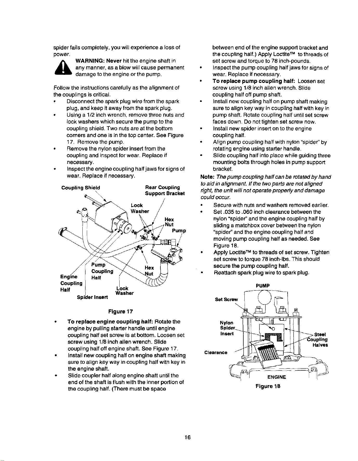
Follow the instructions carefully as the alignment of
the couplings is critical.
• Disconnect the spark plug wire from the spark
plug, and keep it away from the spark plug.
• Using a 1/2 inch wrench, remove three nuts and
lock washers which secure the pump to the
coupling shield. Two nuts are at the bottom
corners and one is in the top center. See Figure
17. Remove the pump.
• Remove the nylon spider insert from the
coupling and inspectfor wear. Replace if
necessary.
• Inspect the engine coupling half jaws for signs of
wear. Replace if necessary.
Coupling Shield Rear Coupling
\ Support Bracket
Lock
Washer
Hex
Nut
?p
Coupling 1
Half ock
Washer
Figure 17
To replace engine coupling half: Rotate the
engine by pulling starter handle until engine
coupling half set screw is at bottom. Loosen set
screw using 1/8 inch allen wrench. Slide
coupling half off engine shaft. See Figure 17.
Installnew coupling halfon engine shaft making
sure to align key way in coupling half with key in
the engine shaft.
Slide coupler half along engine shaft untilthe
end of the shaft is flush with the inner portion of
the coupling half. (There must be space
between end of the engine support bracket and
the coupling half.) Apply LoctiteTM to threads of
set screw and torque to 78 inch-pounds.
• Inspect the pump coupling half jaws for signs of
wear. Replace ifnecessary.
To replace pump coupling half: Loosen set
screw using 1/8 inch alien wrench. Slide
coupling halfoff pump shaft.
Installnew coupling half on pump shaft making
sure to align key way in couplinghalf with key in
pump shaft. Rotate coupling half untilset screw
faces down. Do not tighten set screw now.
• Install new spider inserton to the engine
coupling half.
• Align pump coupling half with nylon "spider" by
rotating engine using starter handle.
Slide coupling half intoplace while guidingthree
mountingbolts through holes in pump support
bracket.
Note: The pump couplinghaff can be rotated by hand
to aid in alignment. If the twoparts are not aligned
nght, the unit will not operate properly and damage
could occur.
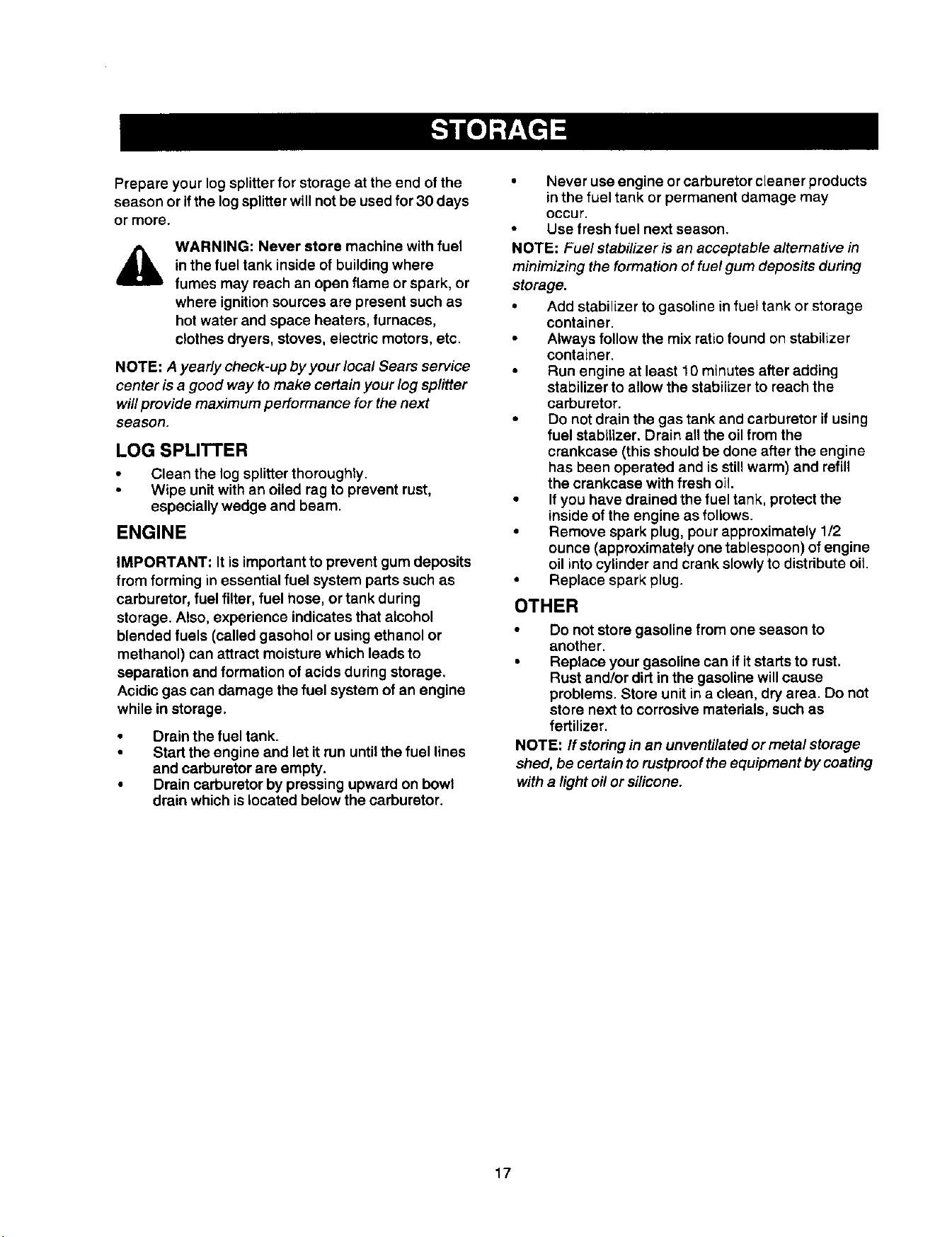
• Secure with nuts and washers removed earlier.
• Set .035 to .060 inch clearance between the
nylon "spider" and the engine coupling half by
sliding a matchbox cover between the nylon
"spider" and the engine coupling half and
moving pump coupling half as needed. See
Figure 18.
• Apply Loctite TM to threads of set screw. Tighten
set screw to torque 78 inch-lbs. This should
secure the pump coupling half.
Reattach spark plug wire to spark plug.
PUMP
s,t 4
Clearance __lves
Figure lg
16
Prepare your log splitter for storage at the end of the
season or if the log splitter will not be used for 30 days
or more.
WARNING: Never store machine withfuel
inthe fuel tank inside of building where
fumes may reach an open flame or spark, or
where ignitionsources are present such as
hot water and space heaters, furnaces,
clothes dryers, stoves, electric motors, etc.
NOTE: A yearly check-up by your local Sears service
center is a good way to make certain your log splitter
willprovide maximum performance for the next
season.
LOG SPLITTER
Clean the log splitterthoroughly.
Wipe unit with an oiled rag to prevent rust,
especially wedge and beam.
ENGINE
IMPORTANT: It is importantto prevent gum deposits
from forming inessential fuel system parts such as
carburetor, fuel filter,fuel hose, or tank during
storage. Also, experience indicates that alcohol
blended fuels (called gasohol or using ethanol or
methanol) can attract moisturewhich leads to
separation and formation of acids during storage.
Acidicgas can damage the fuel system of an engine
while in storage.
Drain the fuel tank.
Start the engine and let it run until the fuel lines
and carburetor are empty.
Drain carburetor by pressing upward on bowl
drain which is located below the carburetor.
Never use engine orcarburetorcleaner products
inthe fuel tank or permanent damage may
Occur.
Use fresh fuel next season.
NOTE: Fuel stabilizer is an aoceptab/e alternative in
mln#771zingthe formation of fuel gum deposits during
storage.
• Add stabilizer to gasoline in fuel tank or storage
container.
Always follow the mix ratio found on stabilizer
container.
• Run engine at least 10 minutes after adding
stabilizer to allow the stabilizer to reach the
carburetor.
• Do not drain the gas tank and carburetor if using
fuel stabilizer. Drain all the oil from the
crankcase (this should be done after the engine
has been operated and is still warm) and refill
the crankcase with fresh oil.
• If you have drained the fuel tank, protect the
inside of the engine as follows.
• Remove spark plug, pour approximately 1/2
ounce (approximately one tablespoon) of engine
oil into cylinder and crank slowlyto distribute oil.
• Replace spark plug.
OTHER
Do not store gasoline from one season to
another.
• Replace your gasoline can if it starts to rust.
Rust and/or dirt in the gasoline will cause
problems. Store unit in a clean, dry area. Do not
store next to corrosive materials, such as
fertilizer.
NOTE: If storingin an unventilated or metal storage
shed, be certain to rustproof the equipment by coating
with a light oil or silicone.
17
Problem
Cylinder rod will not move
Cylinder shaft speed slow while
extending end retracting
Engine runs but wood will not sprit, or
splits too slowly
Engine stalls during splitting wood
Engine will not tum or stalls under low
load
Leaking pump shaft seal
Possible Cause
1. Broken drive shaft,
2. Shipping plugs left in hydraulic hoses,
3. Set screws in coupling not adjusted
properly.
4, Loose shaft coupling.
5. Gear sections damaged.
6. Damaged relief valve.
7, Hydraulic lines blocked.
8, Incorrect oil level.
g. Damaged or blocked directional
valve.
t. Gear sections damaged.
2. Excessive pump inlet vacuum.
3, Slow engine speed.
4. Damaged relief valve.
5. Incorrect oil level.
6. Contaminated oil,
7. Directional valve leaking internally.
8. Internally damaged cylinder,
1, Small gear section damaged.
2. Pump check valve leaking.
3. Excessive vacuum in pump inlet,
4. Incorrect oil level.
5. Contaminated oil
6. Directional valve leaking internally.
7. Internally damaged cylinder.
8. Ovedoaded cylinder.
1. Low horsepower/weak engine.
2. Overloaded cylinder
1, Engine/pump misaligned.
! 2, Frozen or seized pump.
3, Weak engine.
4. Hydraulic lines blocked,
5. Blocked directional valve.
1, Broken drive shaft.
2. Engine/pump misaligned.
3. Gear sections damaged.
4, Poorly positioned shaft seal.
5. Oil breather plugged.
Corrective Action
1. Return unit to Sears service center.
2. Disconnect hydraulic hose, remove
shipping plugs, and reconnect hose.
3. Refer to adjustment secfion of this
manual and adjust the couplers
4. Correct engine/pump alignment.
5. Return unit to Sears service center.
6. Return unit to Sears service center.
7. Flush and clean hydraulic system,
! 8. Check oil level, Refill if necessary,
9. Return unit to Sears service center
1. Return unit to Sears service center.
2. Make certain that the pump inlet
hoses are clear and unblocked. Use
short, large diameter inlet hoses.
3. Return unit to Sears service center.
4. Return unitto Sears service center.
5. Check oil level. Refill if necessary.
6. Drain oil, clean reservoir, refill,make
certain oil return tube is below oil
lever.
7. Return unitto Sears service center.
8. Return unitto Sears service center.
1. Return unit to Sears service center.
2. Return unit to Sears service center.
3. Make certain that the pump inlet
hoses are clear and unblocked. Use
short, large diameter inlet hoses.
4. Check oir level. Refill if necessary.
5. Drain oil, clean reservoir, refill, make
certain oil return tube is below oil
level.
6. Return unitto Sears service center.
7. Return unit to Sears service center.
8. Do not attempt to splitwood against
the grain.
1. Return unit to Sears service center.
2. Do not attempt to splitwood against
the grain. If engine stalls repeatedly,
contact Sears service center.
1. Correct alignment.
2. Return unit to Sears service center.
3. Return unit to Sears service center.
4. Flush and clean hydraulic system.
5. Return unit to Sears service center
1. Return unit to Sears service center.
2. Correct alignment.
3. Return unit to Sears service center.
4. Return unit to Sears service center.
5. Make certain reservoir is properly
vented.
18
Trouble-Shooting Guide continued
Problem Possible Causes
Engine failsto start 1. Dirty air cleaner.
2. Fuel tank empty, or stale fuel.
3. Choke not in ON position.
4. Blocked fuel line.
5. Spark plug wire disconnected.
Corrective Action
1. Serviceaircleaner following instruction_
on page 14 of thismanual.
2,
3.
4.
5.
6. Faulty spark plug. 6.
Engineruns erratic. 1. Unit running on choke, t.
2. Spark plug wire Loose. 2.
3. Blocked fuel Lineor stale fuel. 3.
4. Dirty air cleaner. 4.
5. Carburetor out of adjustment 5.
Engineoverheats 1. Engineoil level low. 1.
2, Dirty air cleaner. 2.
3. Carburetor out of adjustment. 3.
4.
4. Airflow restricted.
Will not splitlogs 1. Reservoir fluid level low, 1.
Leakingcylinder 1. Brokenseals. 1.
2. Scored cylinder 2.
Fill tank with fresh fuel.
Move choke to ON.
Clean fuel line.
Connect spark plug wire to spark
plug.
Service spark plug following
instructions on page 15.
Move choke lever to OFF position.
Connect and tighten spark plug wire.
Clean fuel line. Fill tank with fresh
fuel.
Service air cleaner following
instructions on page 14.
Contact Sears service center.
Fill crankcase with proper oil.
Service air cleaner following
instructions on page 14.
Contact Sears service center.
Stop engine, disconnect spark plug
wire, move blower housing, and
clean.
Refill with Dexron III automatic
transmission fluid.
Return unit to Sears servicecenter.
Return unit to Sears service center.
_, or repairs beyond the minoradjustments listed above,
please contact your nearest SEARS service center.
19
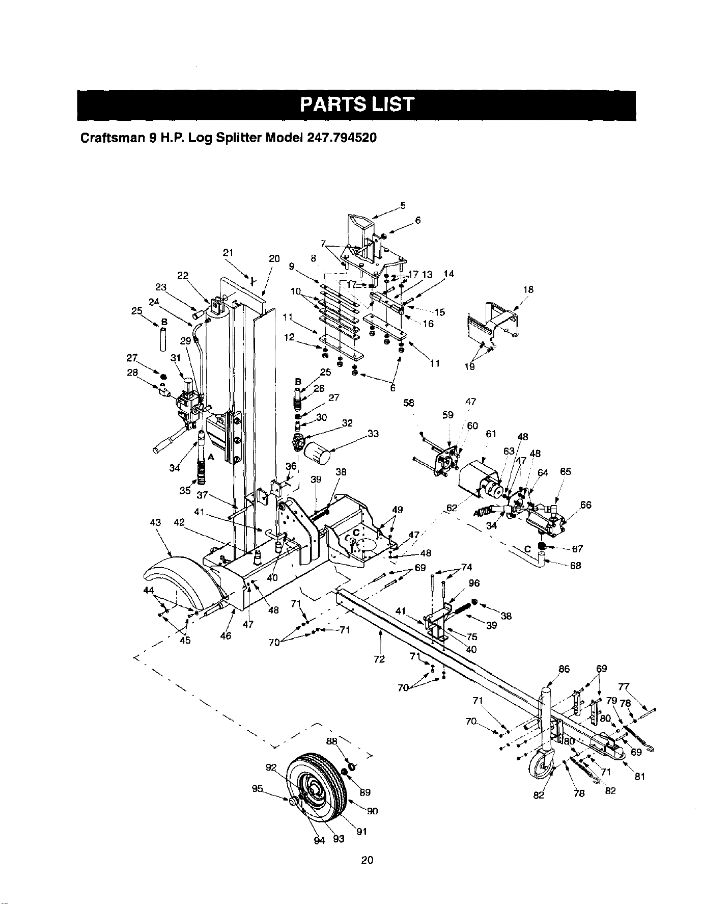
Craftsman 9 H.P. Log Splitter Model 247.794520
22
23
24 _
25
43 42
44
21
2O 8
17 13 14
B_627 6 58
3_ 33
38
18
/
47
59
; 60
61 48
/
49 _.62
64 65
/
/66
96
,<
/ " 45 46
86
/
7!
\
82
69
?8 82
2O
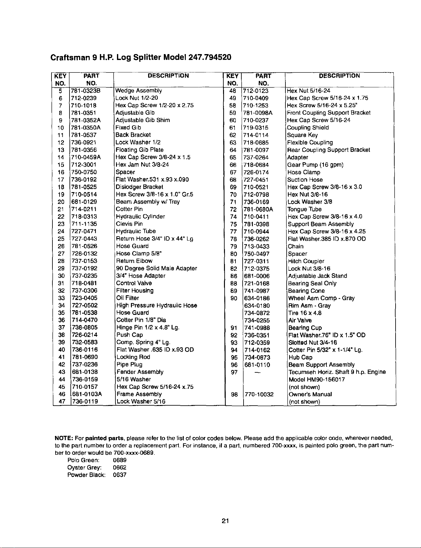
Craftsman 9 H.P, Log Splitter Model 247.794520
KEY
NO.
5
6
7
6
9
10
11
12
13
14
15
16
17
18
19
20
21
22
23
24
25
26
27
28
29
3O
31
32
33
34
35
36
37
38
39
4O
41
42
43
44
45
46
47
PART
NO.
781-0323B
712-0239
1710-1018
781-0351
781-0352A
781-0350A
781-0537
736-0921
781-0356
710-0459A
712-3001
750-0750
736-0192
781-0525
710-0514
681-0129
714-0211
718-0313
711-1135
727-0471
727-0443
781-0526
726-0132
737-0153
737-0192
737-0235
718-0481
737-0306
723-0405
727-0502
781-0538
714-0470
738-0805
726-0214
732-0583
736-0116
761-0690
737-0236
681-0138
736-0159
710-0157
681-0103A
736-0119
DESCRIPTION
Wedge Assembly
Lock Nut 1/2-20
Hex Cap Screw 1/2-20 x 2.75
Adjustable Gib
Adjustable Gib Shim
Fixed Gib
Back Bracket
Lock Washer 1/2
Floating Gib Plate
Hex Cap Screw 3/8-24 x 1.5
Hex Jam Nut 3/8-24
Spacer
Flat Washer.531 x.93 x.090
Dislodger Bracket
Hex Screw 3/8-16 x 1.0" Gr.5
Beam Assembly w/Tray
Cotter Pin
Hydraulic Cylinder
Clevis Pin
Hydraulic Tube
Return Hose 3/4" ID x 44" Lg
Hose Guard
Hose Clamp 5/8"
Return Elbow
90 Degree Solid Male Adapter
3/4" Hose Adapter
Control Valve
Filter Housing
Oil Filter
High Pressure Hydraulic Hose
Hose Guard
Cotter Pin 1/8" Dia
Hinge Pin 1/2 x 4.8" Lg.
Push Cap
Cemp. Spring 4" Lg.
Flat Washer .635 ID x.93 OD
Locking Rod
Pipe Plug
Fender Assembly
5/16 Washer
Hex Cap Screw 5/16-24 x.75
Frame Assembly
Lock Washer 5/16
KEY
NO.
48
49
58
59
60
61
62
63
64
65
66
67
68
69
70
71
72
74
75
77
78
79
80
81
82
86
88
89
90
91
92
93
94
95
96
97
98
PART
NO.
712-0123
710-0409
710-1253
781-0098A
710-0237
719-0315
714-0114
718-0685
781-0097
737-0264
718-0684
726-0174
727-0451
710-0521
712-0798
736-0169
781-0680A
710-0411
781-0396
710-0944
736-0262
713-0433
750-0497
727-0311
712-0375
681-0006
721-0168
74%0987
634-0186
634-0180
734-0872
734-0255
741-0988
736-0351
712-0359
714-0162
734-0873
681-0110
770-10032
DESCRIPTION
Hex Nut 5/16-24
Hex Cap Screw 5/16-24 x 1.75
Hex Screw 5/16-24 x 5,25"
Front Coupling Support Bracket
Hex Cap Screw 5/16-24
Coupling Shield
Square Key
Flexible Coupling
Rear Coupling Support Bracket
Adapter
Gear Pump (16 gpm)
Hose Clamp
Suction Hose
Hex Cap Screw 3/6-16 x 3.0
Hex Nut 3/8-16
Lock Washer 3/8
Tongue Tube
Hex Cap Screw 3/8-16 x 4.0
Support Beam Assembly
Hex Cap Screw 3/8-16 x 4.25
Flat Washer.385 ID x.870 OD
Chain
Spacer
Hitch Coupler
Lock Nut 3/8-16
Adjustable Jack Stand
Bearing Seal Only
Bearing Cone
Wheel Asm Cemp - Gray
Rim Asm - Gray
Tire 16 x 4.8
Air Valve
Bearing Cup
Flat Washer.76" ID x 1.5" OD
Slotted Nut 3/4-18
Cotter Pin 5/32" x 1-1/4" Lg.
Hub Cap
Beam Support Assembly
Tecumseh Horiz. Shaft 9 h.p. Engine
Model HM90-156017
(not shown)
Owner's Manual
(not shown)
NOTE: For painted parts, please refer to the list of color codes below. Please add the applicable color cede, wherever needed,
to the part number to order a replacement part. For instance, if a part, numbered 700-xxxx, is painted polo green, the part num-
ber to order would be 700-xxxx-0689.
Polo Green: 0689
Oyster Grey: 0662
Powder Black: 0637
21
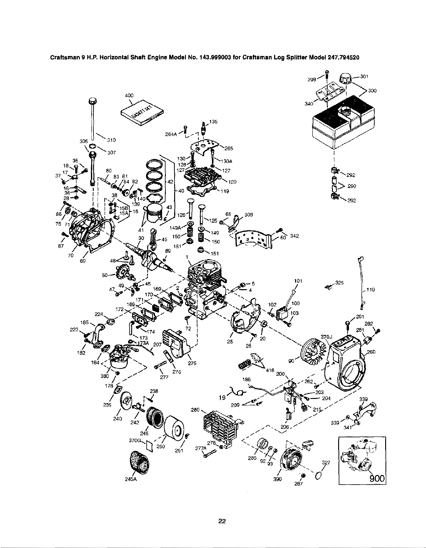
Craftsman9H.P.HorizontalShaftEngineModelNo.143.999003forCraftsmanLogSplitterModel247.794520
75
/ 3o
87
70
6g
I
172,,
224,
173
240
_325
.110
/
245
370G,_r_ _ /
I_ 250
245A
276
251
25
26
282
22
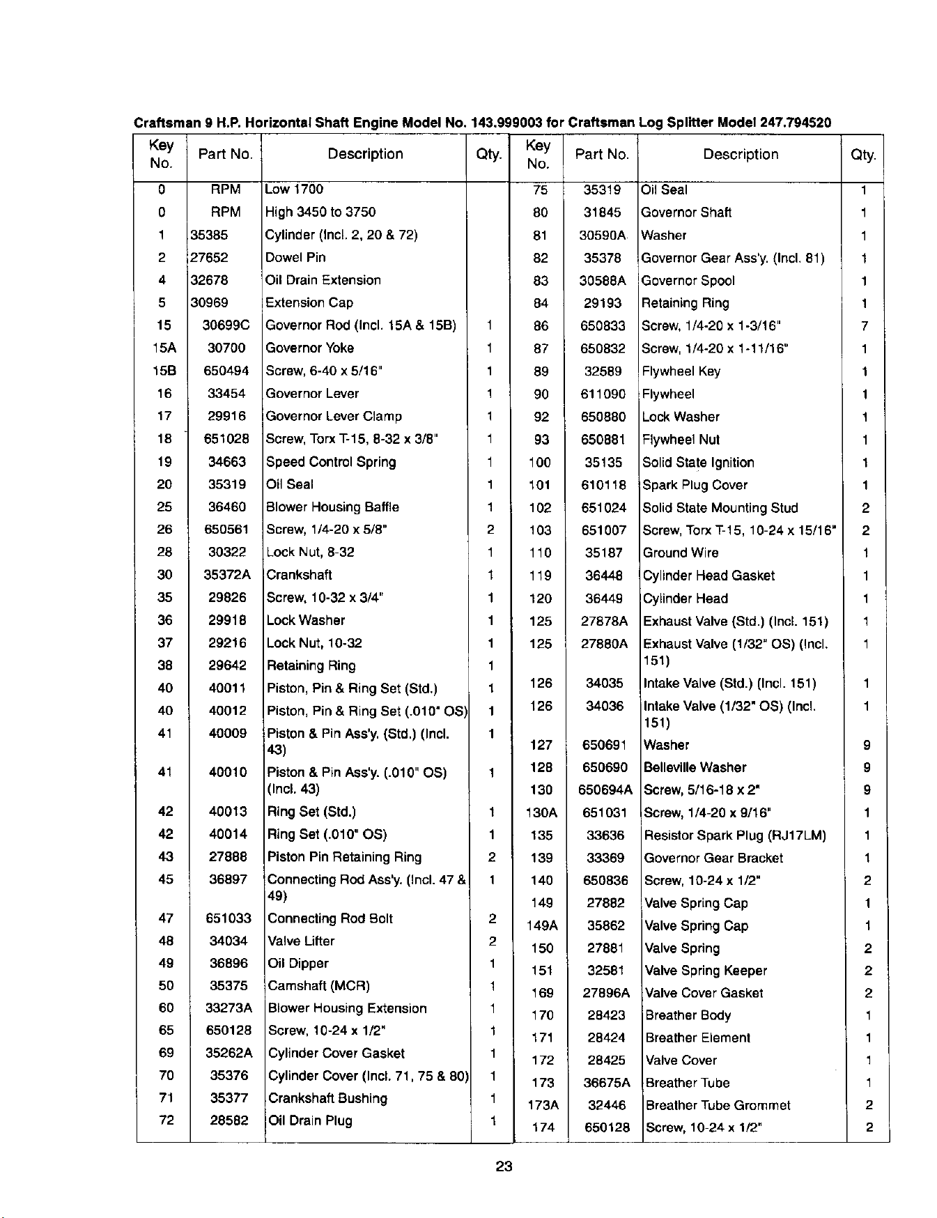
Craftsman 9 H.P. Horizontal Shaft Engine Model No. 143,999003 for Craftsman Log Splitter Model 247.794520
Key Part No. Description Qty. Key Part No. Description
No. No.
0 RPM Low 1700 75 35319 Oil Seal
0 RPM High 3450 to 3750 80 31845 Governor Shaft
1 35385 Cylinder (Incl. 2, 20 & 72) 81 30598A Washer
2 27652 Dowel Pin 82 35378 Governor Gear Ass'y. (Incl. 81)
4 32678 Oil Drain Extension 83 30588A Governor Spool
5 30969 Extension Cap 84 29193 Retaining Ring
15 30699C Governor Rod (Incl. 15A & 15B) 1 86 650833 Screw, 1/4-20 x 1-3/16"
15A 30700 Governor Yoke 1 87 650832 Screw, 1/4-20 x 1-11/16"
15B 650494 Screw, 6-40 x 5/16" 1 89 32589 Flywheel Key
16 33454 Governor Lever 1 90 611090 Flywheel
17 29916 Governor Lever Clamp 1 92 650880 Lock Washer
18 651028 Screw, TorxT-15, 8-32 x 3/8" 1 93 650881 Flywheel Nut
19 34663 Speed Control Spring 1 100 35135 Solid State Ignition
20 35319 Oil Seal 1 101 610116 Spark Plug Cover
25 36460 Blower Housing Baffle 1 102 651024 Solid State Mounting Stud
26 650561 Screw, 1/4-20 x 5/8" 2 103 651007 Screw, Torx T-15, 10-24 x 15/16"
28 30322 Lock Nut, 8-32 1 110 35187 Ground Wire
30 35372A JCrankshaft 1 119 36448 Cylinder Head Gasket
35 29826 Screw, 10-32 x 3/4" 1 120 36449 Cylinder Head
36 29918 Lock Washer 1 125 27878A Exhaust Valve (Std.) (Incl. 151)
37 29216 Lock Nut, 10-32 1 125 27880A Exhaust Valve (1/32" OS) (Incl.
38 29642 Retaining Ring 1 151)
40 40011 Piston, Pin & Ring Set (Std.) 1 126 34035 Intake Valve (Std.) (Incl. 151)
40 40012 Piston, Pin & Ring Set (.010" OS) 1 126 34036 Intake Valve (1/32" OS) (IncL
151)
41 40009 Piston & Pin Ass'y. (Std.) (Incl. 1
43) 127 650691 Washer
41 40010 Piston & Pin Ass'y. (.010" OS) 1 128 650690 Belleville Washer
(Incl. 43) 130 650694A Screw, 5/16-18 x 2"
42 40013 Ring Set (Std.) 1 130A 651031 Screw, 1/4-20 x 9/t6"
42 40014 Ring Set (.010" OS) 1 135 33636 Resistor Spark Plug (RJ17LM)
43 27888 Piston Pin Retaining Ring 2 139 33369 Governor Gear Bracket
45 36897 Connecting Rod Ass'y. (Incl. 47 & 1 140 650836 Screw, 10-24 x 1/2"
49) 149 27882 Valve Spring Cap
47 651033 Connecting Rod Bolt 2 149A 35862 Valve Spring Cap
48 34034 Valve Lifter 2 150 27881 Valve Spring
49 36896 Oil Dipper 1 151 32581 Valve Spring Keeper
50 35375 Camshaft (MCR) 1 169 27896A Valve Cover Gasket
60 33273A Blower Housing Extension 1 170 28423 Breather Body
65 650128 Screw, 10-24 x 1/2" 1 171 28424 Breather Element
69 35262A Cylinder Cover Gasket 1
172 28425 Valve Cover
70 35376 Cylinder Cover (Incl. 71,75 & 80 1 173 36675A Breather Tube
71 35377 Crankshaft Bushing 1 173A 32446 Breather Tube Grommet
72 28582 Oil Drain Plug 1 174 650126 Screw, 10-24 x 1/2"
Qty.
1
1
1
1
1
1
7
1
1
1
1
1
1
1
2
2
1
1
1
1
1
9
9
9
1
1
1
2
1
1
2
2
2
1
1
1
1
2
2
23
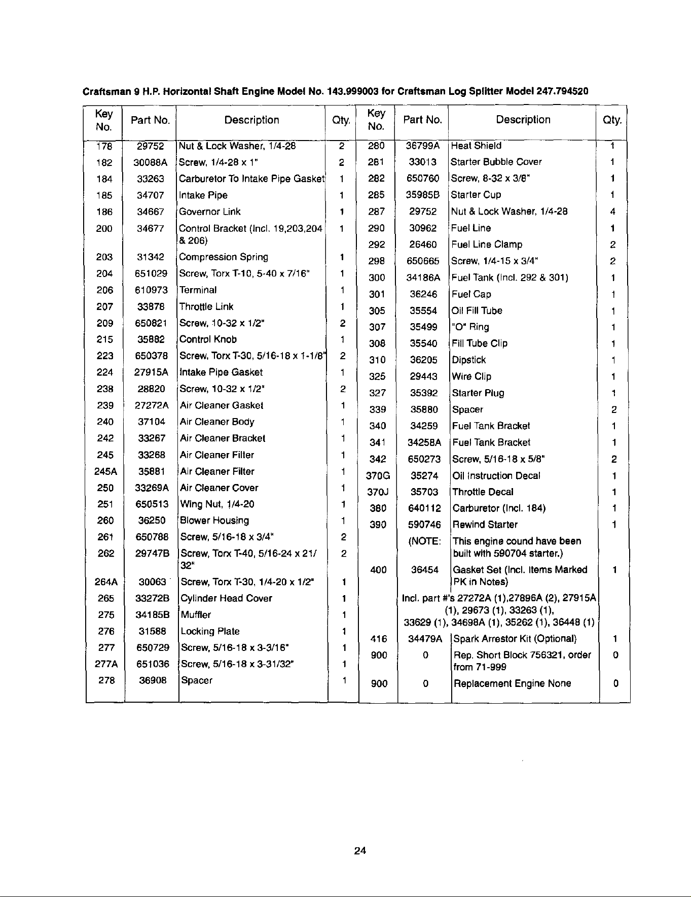
Craftsman 9 H.P. Horizontal Shaft Engine Model No. 143.999003 for Craftsman Log Splitter Model 247.794520
Key
No.
178
182
184
185
186
200
2o3
204
206
207
209
215
223
224
238
239
24o
242
245
245A
25O
251
260
261
262
264A
265
275
276
277
277A
278
Part No.
29752
30088A
33263
34707
34667
34677
31342
651029
Description Qty.
Key Part No.
No.
280 36799A
281 33013
282 650760
285 35985B
287 29752
290 30962
292 26460
298 650665
300 34186A
Nut & Lock Washer, 1/4-28 2
Screw, 1/4-28 x 1" 2
Carburetor To Intake Pipe Gasket 1
Intake Pipe 1
Governor Link 1
Control Bracket (Incl. 19,203,204 1
& 2O6)
Compression Spring 1
Screw, Torx 1"-10,5-40 x 7/16" 1
610973 Terminal
33878 Throttle Link
650821 Screw, 10-32 x 1/2"
35882 Control Knob
650378
1
1
2
1
Screw, Torx T-30, 5/16-18 x 1-1/8'
301 36246
305 35554
307 35499
308 35540
Description
Heat Shield
Starter Bubble Cover
Screw, 8-32 x 3/8"
Starter Cup
Nut & Lock Washer, 1/4-28
Fuel Line
Fuel Line Clamp
Screw, 1/4-15 x 3/4"
Fuel Tank (Incl. 292 & 301)
27915A intake Pipe Gasket
28820 Screw, 10-32 x 1/2"
27272A Air Cleaner Gasket
37104 Air Cleaner Body
33267 Air Cleaner Bracket
33268 Air Cleaner Filter
35881 Air Cleaner Filter
33269A Air Cleaner Cover
650513 Wing Nut, !/4-20
36250 Slower Housing
650788 Screw, 5/16-18 x 3/4"
2 310
1 325
2 327
1 339
1 340
1 341
1 342
1 370G
1 370J
1 380
1 390
2
4OO
Fuel Cap
Oil Fill Tube
"O" Ring
Fill Tube Clip
Screw, Torx T-4O, 5/16-24 x 21/
32"
Screw, Torx 1"-30, 1/4-20 x 1/2"
29747B
30063
2
1
36205
29443
35392
35880
34259
34258A
650273
35274
35703
640112
590746
(NOTE:
36454
Dipstick
Wire Clip
Starter Plug
Spacer
Fuel Tank Bracket
Fuel Tank Bracket
Screw, 5/16-18 x 5/8"
Oil instruction Decal
Throttle Decal
Carburetor (Incl. 184)
Rewind Starter
This engine cound have been
built with 590704 starter.)
Gasket Set (Incl. Items Marked
PK in Notes)
33272B
34185B
31588
650729
651036
36908
Cylinder Head Cover
Muffler
Locking Plate
Screw, 5/16-18 x 3-3/16"
Screw, 5/16-18 x 3-31/32"
Spacer
1
1
1
1
1
1
416
9OO
900
Incl. part #'s 27272A (1),27896A (2), 279151
(1), 29673 (1), 33263 (1),
33629 (1), 34698A (1), 35262 (1), 36448 (1)
34479A Spark Arrestor Kit (Optional)
0 Rep. Short Block 756321, order
from 71-999
0 Replacement Engine None
24
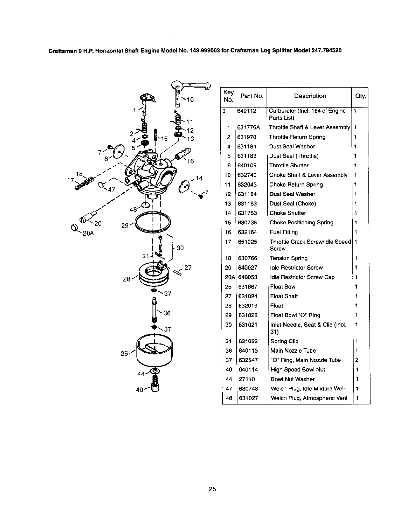
Craftsman 9 H.P. Horizontal Shaft Engine Model No. 143.999003 for Craftsman Log Splitter Model 247.794520
Key Part No. Description Qty.
No.
0 640112 1
1 631776A
2 631970
_i1_ 4 631184
7 /
5 631183
/ "_', 6 640109
/
18_ / / ._. 10 632740
17_-_¢" // ' 11 632043
/ _1_7 12 i631184
/t/ I 13 631183
_2 / 14 631753
0 15 630735
_20A 16 632164
17 651025
40fl
•_'_, 37
18
2O
20A
25
27
28
29
30
31
36
37
40
44
47
48
630766
640027
640053
631867
631024
632019
631028
631021
631022
540113
632547
640114
27110
630748
631027
Carburetor (IncL 184 of Engine
Parts List)
Throttle Shaft & Lever Assembly
Throttle Return Spring
Dust Seal Washer
Dust Seal (Throttle)
Throttle Shutter
Choke Shaft & Lever Assembly
; Choke Return Spring
Dust Seal Washer
Dust Seal (Choke)
Choke Shutter
Choke Positioning Spring
Fuel Fitting
Throttle Crack Screw/Idle Speed
Screw
Tension Spring
Idle Restrictor Screw
Idle Restrictor Screw Cap
Float Bowl
Float Shaft
Float
Float Bowl "O" Ring
Inlet Needle, Seat & Clip (Incl.
31)
Spring Clip
Main Nozzle Tube
"O" Ring, Main Nozzle Tube
High Speed Bowl Nut
Bowl Nut Washer
Welch Plug, Idle Mixture Well
Welch Plug, Atmospheric Vent
1
1
1
1
1
1
1
1
1
1
1
1
1
1
1
1
1
1
2
11
1
1
1
25
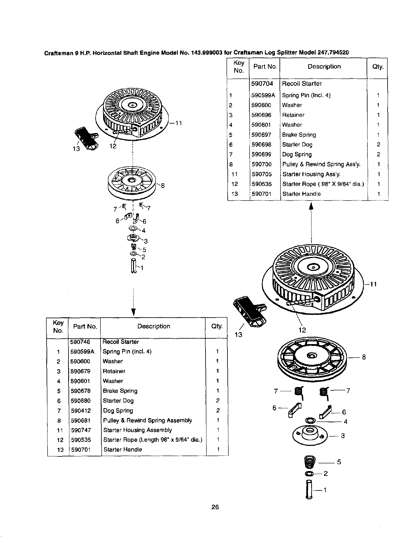
Craftsman 9 H.P. Horizontal Shaft Engine Model No, 143,999003 for Craftsman Log Splitter Model 247.794520
12
\8
J
6 / _6
_'_5
_'2
-11
Key
No.
Part No. Description
1
2
3
4
5
6
7
8
11
12
13
590704
590599A
$96600
590696
590601
590697
590698
590699
590700
590705
590535
590701
Recoil Starter
Spring Pin (Incl. 4)
Washer
Retainer
Washer
Brake Spring
Starter Dog
Dog Spring
Pulley & Rewind Spring Ass'y.
Starter Housing Ass'y.
Starter Rope ( 98" X 9/64" dia.)
Starter Handle
Qty.
1
1
1
1
1
2
2
1
1
1
1
V
Key Part No. Description Qty.
No.
590746
1 590599A
2 590600
3 590679
4 590601
5 590678
6 590680
7 590412
8 590681
11 590747
12 590535
13 590701
Recoil Starter
Spring Pin (Incl. 4) 1
Washer 1
Retainer 1
Washer 1
Brake Spring 1
Starter Dog 2
Dog Spring 2
Pulley & Rewind Spring Assembly 1
Starter Housing Assembly 1
Starter Rope (Length 98" x 9/64" dia.) 1
Starter Handle 1
26
13
12
O 4
_--5
O--2
In U.S.A. or Canada
for in-home major brand repair service:
Call 24 hours a day, 7 days a week
1-800-4-MY-HOME sM(1-800"469-4663)
Pare pedir servicio de reparaci6n a domicillio -- 1-800-676-5811
Au Canada pour tout le service ou les pi_ces -- 1-800-469-4663
For the repair or replacement parts you need:
Call 6 a.m. -- 11 p.m. CST, 7 days a week
PartsDirectsM
1-800-366-PART (1-800-366-7278)
Pare ordenar piezas con entrega a domicillio -- 1-800-659-7084
For the location of a Sears Service Center in your area:
Call 24 hours a day, 7 days a week
1-800-488-1222
To purchase or inquire about a Sears Maintenance Agreement:
Call 7 a.m. -- 5 p.m. CST, Monday -- Saturday
1-800-827-6655
SEARS
HomeCentrar
44
