16-PIN 12V/24V OBD BREAKOUT BOX - CAR,
MOTORCYCLE, TRUCK, BOAT, VAN
MODEL NO: VS8813
Thank you for purchasing a Sealey product. Manufactured to a high standard, this product will, if used according to these instructions,
and properly maintained, give you years of trouble free performance.
IMPORTANT: PLEASE READ THESE INSTRUCTIONS CAREFULLY. NOTE THE SAFE OPERATIONAL REQUIREMENTS, WARNINGS & CAUTIONS. USE
THE PRODUCT CORRECTLY AND WITH CARE FOR THE PURPOSE FOR WHICH IT IS INTENDED. FAILURE TO DO SO MAY CAUSE DAMAGE AND/OR
PERSONAL INJURY AND WILL INVALIDATE THE WARRANTY. KEEP THESE INSTRUCTIONS SAFE FOR FUTURE USE.
1. SAFETY
WARNING! To prevent personal injury or damage to vehicles and/or the tool, read this instruction manual rst and observe the
following safety precautions.
9 Always perform automotive testing in a safe environment.
9 Wear safety eye protection.
9 Keep clothing, hair, hands, tools, test equipment, etc. away from all moving or hot engine parts.
9 Operate the vehicle in a well ventilated work area. Exhaust gases are poisonous.
9 Put blocks in front of the drive wheels and never leave the vehicle unattended while running tests.
9 Use extreme caution when working around the ignition coil, distributor cap, ignition wires and spark plugs. These components
create hazardous voltages when the engine is running.
9 Put the transmission in PARK (for automatic transmission) or NEUTRAL (for manual transmission) and make sure the parking brake
is engaged.
9 Keep a re extinguisher suitable for petrol/chemical/electrical res nearby.
8 DO NOT connect or disconnect any test equipment while the ignition is on or the engine is running.
8 DO NOT use the tester in the presence of static electricity.
9 Keep tester dry, DO NOT use in wet locations.
2. INTRODUCTION
Test the onboard diagnostics port for any faults before connecting other diagnostic devices to the DLC. The breakout box is designed
to be connected in series with 16-pin OBDII/EOBDII diagnostic equipment. It can also be connected to multimeters and oscilloscopes.
Compatible with 12 and 24V systems. The selectable pin voltage indicator shows the real-time voltage of the selected pin.
Communication Protocol Indicator - Pin 6 = CAN H, Pin 14 = CAN L, Pin 2 = VPW+, PWM+, Pin 10 = PWM-, Pin 7 = K_LINE and Pin
15 = L_LINE. Overload protection protects any connected diagnostic equipment from damage.
3. SPECIFICATION
Model No: ................................................................. VS8813
Weight: ........................................................................ 0.24kg
Input Voltage DC: ......................................................... 9-32V
Maximum Load: ..............................................................2.0A
Resolution: ....................................................................: 0.1V
Overload Protection: ........................................................ Yes
Reverse Polarity Protection: .............................................Yes
Operating Temperature: ............................................ 0°-50°C
Cable Length:.............................................................700mm
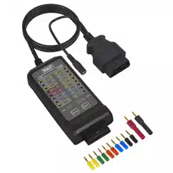
4. FEATURES
1. Signal LED
2. Probe socket
3. Pin and volt display screen
4. Select and reset buttons
5. OBD male
6. OBD female
7. 12-24v input
8. Probes
INPUT VOLTAGE DC: ASSEMBLY & INSTALLATION
VS8813 Issue:1 31/10/24
Original Language Version
© Jack Sealey Limited
Refer to
instructions
Wear eye
protection
fig.
1
5. OPERATION
5.1. ALARM (16 pin power pins only)
SLOW ALARM SOUND:
12V system - if voltage is lower than 11.8V denotes low voltage present
24V system - if voltage is lower than 23.6V denotes low voltage present
URGENT ALARM SOUND:
12V system - if voltage is higher than 15.5V denotes high voltage present
24V system - if voltage is higher than 31V denotes high voltage present
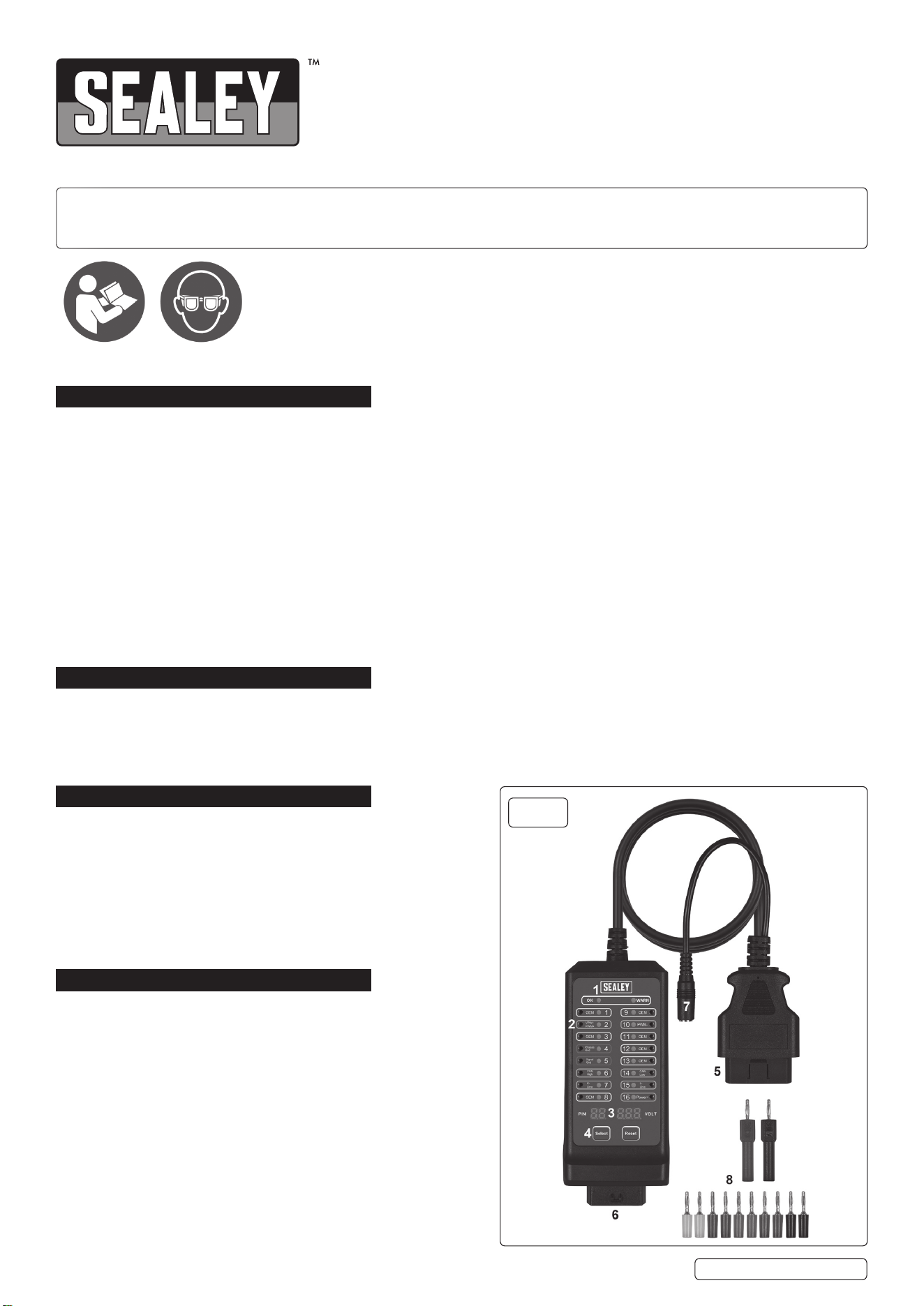
5.2. SIGNAL LED g1.2
OK light on (green): all normal no short circuit, no reverse polarity, no constant voltage on pins 3, 8, 9, 11, 12, 13, voltage on pins 1, 2,
6, 7, 10, 14, 15, (whether constant voltage or pulse signal).
Warning light on (yellow): There is constant voltage on pins: 3, 8, 9, 11, 12, 13, or CAN bus polarity error VCANH<VCANL.
5.3. BUTTONS
5.3.1. RESET BUTTON: To restore default settings, the default pin is 16.
5.3.2. SELECT BUTTON: Used to select the pin for testing voltage.
Press the SELECT button, the pin number will switch to the next pin, and
display the current voltage value.
5.3.3. STATUS INDICATING LED Fig.2
VS8813 is suitable for 12V and 24V systems. Once the DLC is inserted,
it will begin to check whether there is voltage at the pin.
If voltage is detected the corresponding LED lights will show:
Protocol indicator light 2, 6, 7, 10, 14, 15--green/red LED
Green: Indicates protocol communication (pulse) signal is normal.
Red: Indicates voltage is constant.
According to the communication protocol: Pin6: CANH; Pin14: CANL
Pin 2: VPW+PWM+; Pin10: PWM-
Pin7: K_LINE
Pin15: L_LINE
When the signal voltage changes is detected, the green LED will ash
accordingly.
If the voltage detected by the unit on pins is constant, LED will remain and turn
red.
Original Language Version
© Jack Sealey Limited
VS8813 Issue:1 31/10/24
fig.
2
Sealey Group, Kempson Way, Suffolk Business Park, Bury St Edmunds, Suffolk. IP32 7AR
01284 757500 sales@sealey.co.uk www.sealey.co.uk
ENVIRONMENT PROTECTION
Recycle unwanted materials instead of disposing of them as waste. All tools, accessories and packaging should be sorted, taken to
a recycling centre and disposed of in a manner which is compatible with the environment. When the product becomes completely
unserviceable and requires disposal, drain any fluids (if applicable) into approved containers and dispose of the product and fluids
according to local regulations.
Note: It is our policy to continually improve products and as such we reserve the right to alter data, specifications and component parts
without prior notice.
Important: No Liability is accepted for incorrect use of this product.
Warranty: Guarantee is 12 months from purchase date, proof of which is required for any claim.
WEEE REGULATIONS
Dispose of this product at the end of its working life in compliance with the EU Directive on Waste Electrical and Electronic Equipment
(WEEE). When the product is no longer required, it must be disposed of in an environmentally protective way. Contact your local solid
waste authority for recycling information.
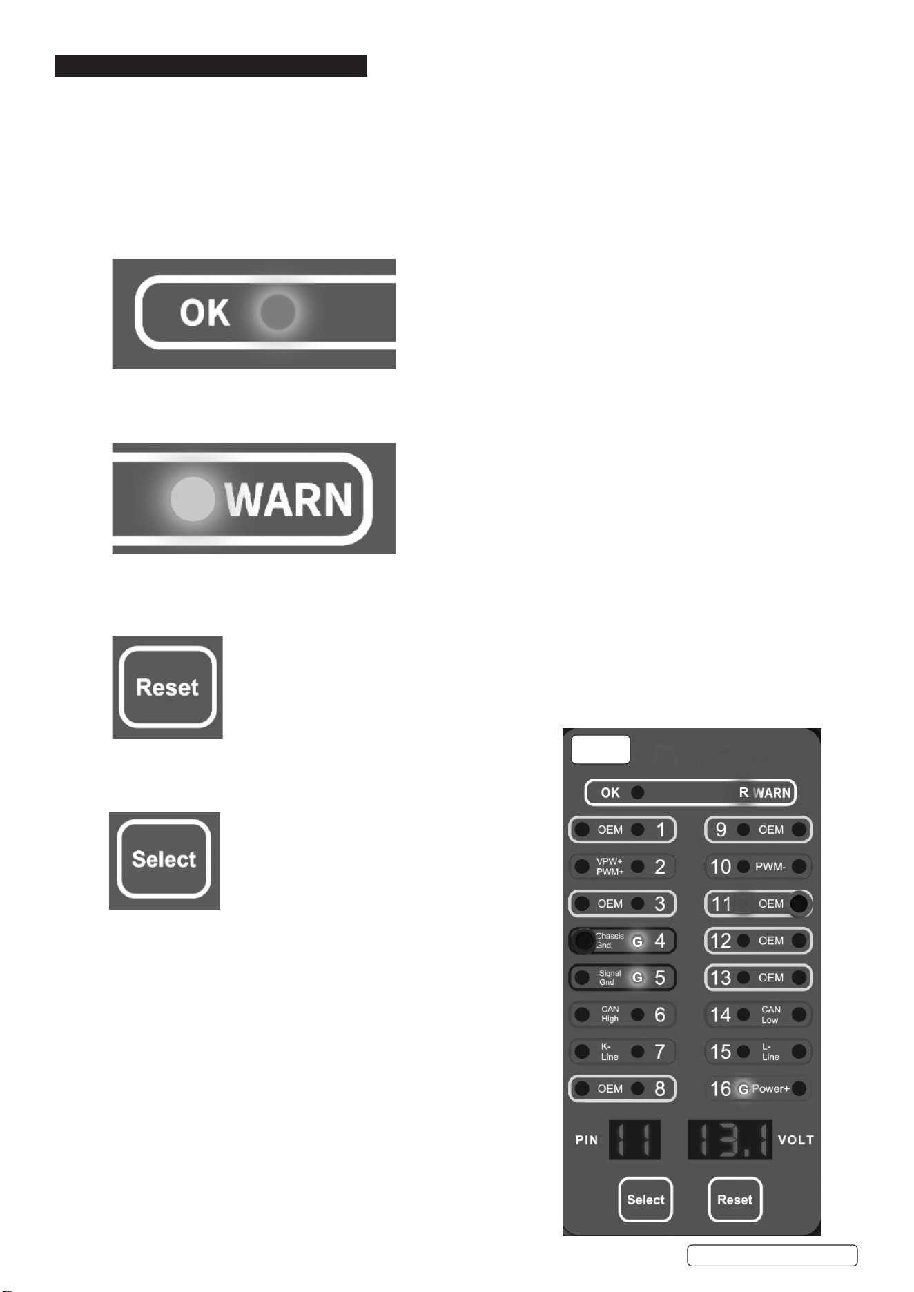
Fig.3: Pin 2 has a pulse signal and a green ashing LED.
5.3.4. USER DEFINED COMMUNICATION INDICATOR LED
User-dened communication indicator light 1, 3, 8, 9, 11, 12, 13--
yellow/red LED
Yellow: communication ( pulse ) signal normal.
Red: lndicates voltage is constant.
If pulse voltage is detected on pins 1, 3, 8, 9, 11, 12, 13,
their respective LED turn ickering yellow.
If the voltage on pins is constant, LED will remain red.
Pin 11 has a constant voltage signal, the red LED is permanently on.
Note 1 : Due to the uctuation of voltage readings in pulse voltage,
this unit only displays the peak-to-peak voltage ( VPP) of the pulse.
Note 2 : Pin 1 whether pulse or constant voltage, the OK LED is on.
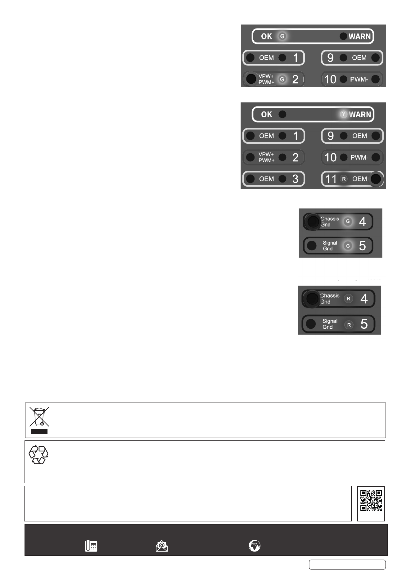
5.3.5. POWER INDICATOR LED
Power indicator light PINs 4/5: green/red LED, PIN 16: green LED.
When the breakout box is inserted into the vehicle DLC and reverse polarity is detected
at pins 4 and 5, the LED turns red, indicating that the polarity is incorrect.
When the polarity is correct 16 PIN is lit green, otherwise it will not be lit.
Original Language Version
© Jack Sealey Limited
REGISTER YOUR
PURCHASE HERE
VS8813 Issue:1 31/10/24
Green: correct earth (-)
Red: reverse polarity detected (+)
