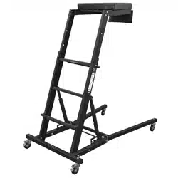
TOPSIDE CREEPER
MODEL NO: SCRT01
Thank you for purchasing a Sealey product. Manufactured to a high standard, this product will, if used according to these
instructions, and properly maintained, give you years of trouble free performance.
IMPORTANT: PLEASE READ THESE INSTRUCTIONS CAREFULLY. NOTE THE SAFE OPERATIONAL REQUIREMENTS, WARNINGS & CAUTIONS. USE
THE PRODUCT CORRECTLY AND WITH CARE FOR THE PURPOSE FOR WHICH IT IS INTENDED. FAILURE TO DO SO MAY CAUSE DAMAGE AND/OR
PERSONAL INJURY AND WILL INVALIDATE THE WARRANTY. KEEP THESE INSTRUCTIONS SAFE FOR FUTURE USE.
1. INTRODUCTION
Multi height and angle adjustments to work in comfort on high level engines on jeeps, pickups, trucks, SUV’s, agricultural vehicles, and more.
Work at the right height and angle in comfort, on the 60mm deep foam, heavy vinyl covered body pad. Heavy-duty steel framework, powder
coat painted for an anti-scratch/rust nish. Easy-rolling Ø75mm composite swivel castors (two lockable). Folding design for easy transport and
storing.
2. SAFETY
WARNING!: Read and understand all instructions before assembling or using the creeper. Keep this manual for safety warnings,
precautions, operating or maintenance instructions.
8 DO NOT spend long periods on a creeper without regular breaks (tiredness is a risk).
8 DO NOT use the creeper if contaminated, e.g. with wet paint, mud, oil or snow.
8 DO NOT use the creeper outside in adverse weather conditions, such as strong wind or wet conditions.
8 DO NOT modify the creeper design. Only qualied service personnel should maintain or repair the tool.
8 DO NOT move a creeper while mounted on it.
8 DO NOT stand or sit on the chest pad deck.
8 DO NOT use the creeper to work over a running engine.
8 DO NOT use the tool if any parts are damaged, broken or misplaced. Only qualied service personnel to maintain or repair the tool.
8 DO NOT exceed the maximum load capacity of the creeper (150kg).
9 Always ensure height adjustment bar is securely xed in one of the ve position slots prior to using.(refer to section 5.2 to adjust
working height).
9 Always lock castors (g.2) before use.
9 Lean your chest onto the deck cushion gently. Avoid causing a shock load by jumping or falling onto it.
9 Prevent damage to the creeper when transporting e.g. by fastening it. Ensure fasteners are suitably placed to prevent damage.
9 Ensure the creeper is suitable for the task to be undertaken.
9 For professional use, a risk assessment shall be carried out respecting the legislation in the country of use.
9 When positioning the creeper take into account the risk of collision with the creeper from pedestrians, vehicles or doors. Secure
nearby doors (not re exits) and windows in the work area where possible.
9 Always lock castors before mounting.
9 Keep work area clear, well lit and free of distractions and keep bystanders away from work area.
9 Wear suitable PPE for task being carried out i.e safety goggles, gloves, work wear.
NOTE: The maximum capacity listed (150kg) includes the user, tools, equipment and personal items.
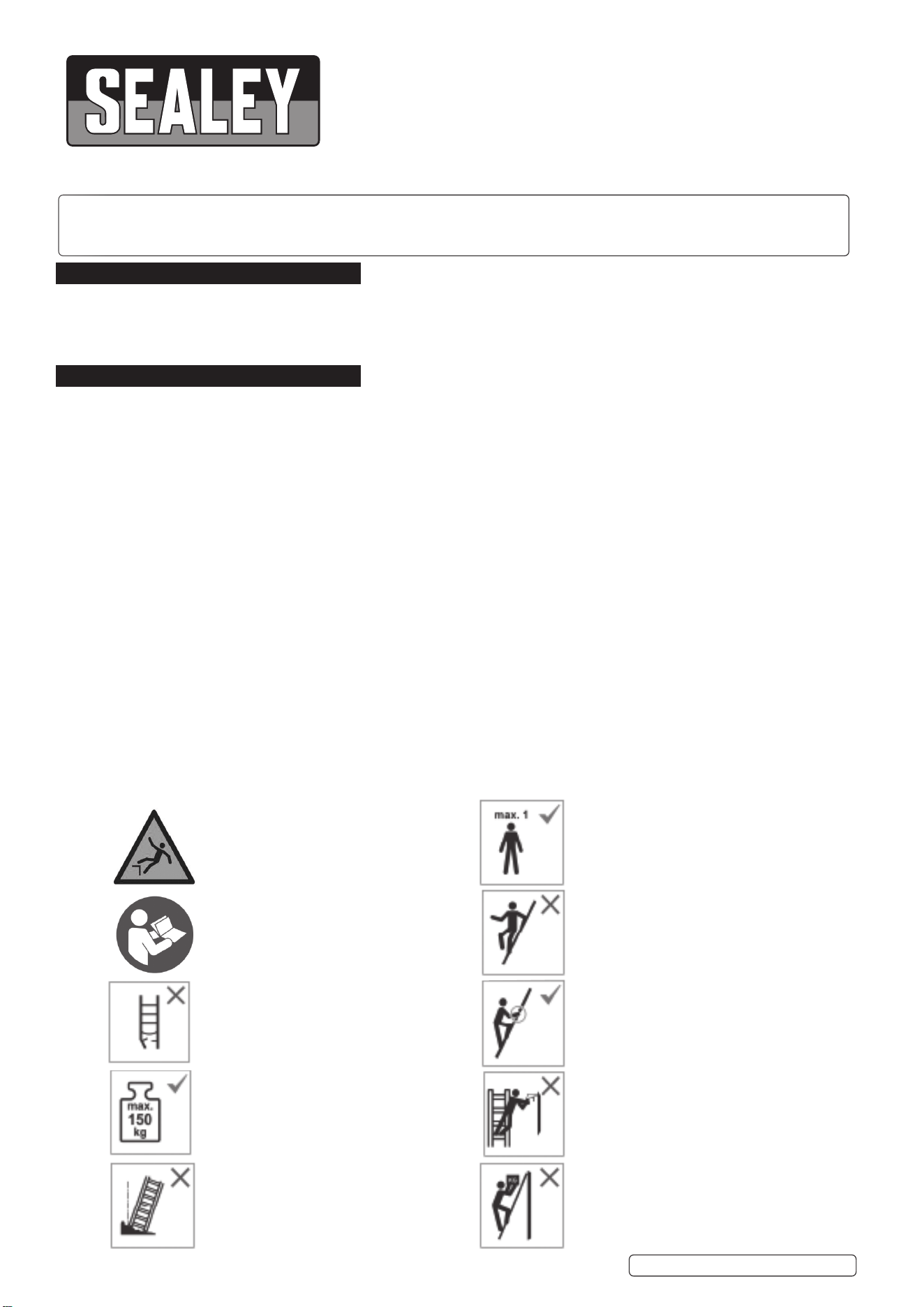
2.1. SAFETY SYMBOLS
SCRT01 Issue 3 26/06/24
Original Language Version
© Jack Sealey Limited
Refer to instruction manual/booklet
Inspect the creeper after delivery. Before
every use visually inspect the creeper to
check it is not damaged and is safe to use.
DO NOT use a damaged creeper.
Maximum total load
DO NOT use creeper on uneven or unstable
surfaces.
Maximum number of users is 1.
DO NOT ascend or descend unless you are
facing the creeper.
Keep a secure grip on the creeper when
ascending/descending. Maintain handhold
whilst working from a creeper or take
additional safety precautions if you cannot.
Avoid work that imposes a sideways load on
Creeper, such as side-on drilling through
solid materials.
DO NOT carry equipment which is heavy or
dicult to handle when using a creeper.
WARNING: Falling from creeper.
This warning sign shall appear on each
marking on the creeper at the rst place.
Original Language Version
© Jack Sealey Limited
SCRT01 Issue 3 26/06/24
3. SPECIFICATION
Model No.: ............................................................... SCRT01
Capacity: ...................................................................... 150kg
Net weight: ..................................................................... 29kg
Size: ..... L-1375, W-Front 775 x Rear 750, H-1190 - 1820mm
4. ASSEMBLY
4.1. Remove the parts and accessories from the packaging and inspect for
damage. Make sure that all items in the contents are included.
WARNING! DO NOT operate the tool if any part is missing. Replace
the missing part before operating. Failure to do so could result in
a malfunction and personal injury.
NOTE: Letter references in parenthesis (i.e. A) refer to the Parts Information.
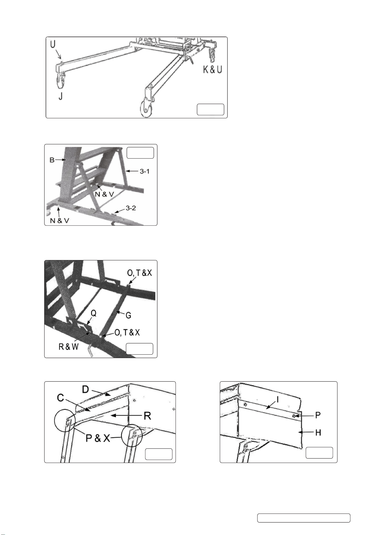
4.2. Assemble the right and left legs (E & F) (g.1) to the base frame (A).
4.3. Insert the end of each leg into the base frame’s openings and align the
bolt holes. The height adjustment notches (g. 1-1) will be on the inside
and the legs must angle outwards. Secure each leg with a frame bolt
(N) and locknut (V). Insert two leg lock pins (M) and push ends down
to secure the legs.
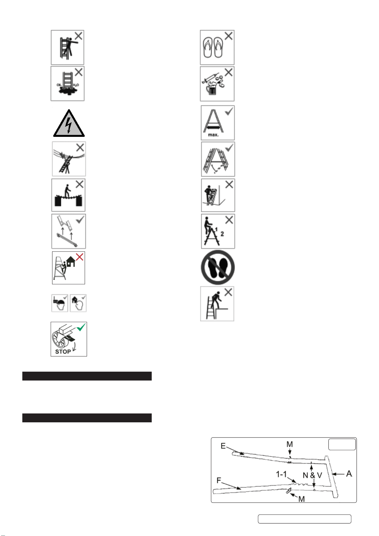
Use non-conductive materials for
unavoidable live electrical work.
DO NOT use the creeper as a bridge.
If a creeper is delivered with stabilizer bars
The bars should be xed by the user before
The rst use. This shall be described on the
creeper and in the user instruction.
DO NOT use creeper for tasks it is not
intended for.
Creeper for professional and domestic use.
WARNING: Electrical hazard. Identify any
electrical risks in the work area, such as
overhead lines or other exposed electrical
equipment and DO NOT use the creeper
where electrical risks occur.
WARNING:
Use the creeper with restraint devices
engaged only.
Standing creepers shall not be used as a
leaning creeper unless it is designed to do
so.
DO NOT stand on the top two steps/rungs
of a standing creeper without a platform and
a hand/knee rail.
Horizontal surfaces which look like a
platform but are not designed for standing
on (e.g. a plastic work tray) shall be clearly
indicated on their surface.
DO NOT step o the side of standing
creeper onto another surface.
Open the creeper fully before use.
Use only when brake is activated.
DO NOT overreach.
DO NOT erect creeper on contaminated
surfaces.
DO NOT wear unsuitable footwear when
working on creeper.
DO NOT use the creeper if you are not
t enough. Certain medical conditions or
medication, alcohol or drug abuse could
make creeper use unsafe.
g.1
4.4. Attach the front castors (J) (g.2) by inserting the stem of each castor through the end of each leg and securing it with a ange
nut (U). Install rear locking castors (K) to base frame in same manner. Lock rear wheels in place for the remainder of the installation.
4.5. Install the ladder assembly (B) by inserting a frame bolt (N) through each side of the base frame and lower ladder assembly. Secure
each bolt with a lock nut (V). Swing the ladder’s angle support (g. 3-1) into the height adjustment notches (g. 3-2). Make sure the
crossbar is rmly in place.
4.6. Place the leg cross support (G) (g.4) on both legs (E & F) (g.1), aligning bolt holes. Insert cross support bolt (O) through each end
of leg cross support and leg. Slide a washer (T) over one bolt and secure with a lock nut (X). Repeat with the other cross support bolt.
4.7. Attach the height the plate (Q) (g.4). Match the angled opening with the adjustment notches. Insert a height adjustment plate bolt (R)
through the bolt hole at each end of the plate. Secure each bolt with a locknut (W). Repeat on the other side.
4.8. Attach the chest deck frame (C) (g.5) to the top of the ladder assembly (B) using three chest frame bolts (P) and locknuts (X) on each
side. Attach the chest deck pad (D) using two cross head screws (R) from underneath.
4.9. Place the pouch bracket (I) (g.6) over the pouch (H) and align the screw holes. Insert a cross head screw (P) through the screw
holes. Line up protruding screws with the holes in the deck frames front panel. Secure the pouch to the deck frame with the screws.
Original Language Version
© Jack Sealey Limited
SCRT01 Issue 3 26/06/24
g.2
g.3
g.4
g.5
g.6

5. OPERATION
WARNING!: Read and understand all instructions before assembling or using the creeper.
8 DO NOT make any adjustement whilst anyone is mounted on the creeper.
9 Undertake a risk assessment of task and work area before commencing any task.
9 Ensure the creeper is correctly and safely assembled and undamaged before use.
WARNING!: Keep hands and ngers clear while adjusting the height of the creeper pad.
9 Position the creeper to enable safe access to the area of interest.
9 Ensure bumper pads (item L on Parts Info.) are placed over angle support arms and ladder assembly (item B on Parts Info.) to
prevent scung of vehicle.
9 Ensure castors are locked before using the creeper.
5.1. ADJUSTING ANGLE LEAN-IN
5.1.1. There are three dierent lean-in angles that allow the user to adjust positioning. This helps the user to maximize safety and productivity. To
adjust angle lean-in:
5.1.2. Lock castors (g.2 - K) by pressing the lock tab with your foot on each of the locking castors.
5.1.3. Push back on the climbing section (g.3-1).
5.1.4. Move angle adjustment to one of the three notches located on the base.
5.2. CHANGING WORKING HEIGHT
5.2.1. The working height of the creeper is adjustable form 1190mm to 1820mm to suit work requirements.
5.2.2. To change the working height, lock castors (g.2 - K) by pressing the lock tab with your foot on each of the locking castors.
5.2.3. Grasp a step within the sliding section with one hand while using the other hand to pull one of the spring loaded locking pins outward.
Rotate the pin so it does not slide back into the locking slot.
5.2.4. Repeat step 5.2.3 on the other side of the sliding section to remove the second spring loaded locking pin.
IMPORTANT: rmly hold a step within the sliding section when the second spring loaded locking pin is removed from the locked
position. This prevents the sliding section from free falling which could cause serious personal injury.
5.2.5. While holding a step within the sliding section with one hand guide one of the spring loaded locking pins into its corresponding hole in the
outside rail.
5.2.6. While holding the sliding section, move it up or down as needed until the locking pin drops into one of the height adjustment holes
located in the side rails of the sliding section.
5.2.7. Guide and insert the second spring loaded locking pin through both the outside rail and oval shaped hole of inside sliding section rail.
6. MAINTENANCE
6.1. Maintain the tool with care. A tool in good condition is ecient, easier to control and will have fewer problems.
6.2. Inspect the tool components periodically. Repair or replace damaged or worn components. Only use identical replacement parts when
servicing.
6.3. Maintain the tool’s labels and name plates. These carry important information.
WARNING! Only qualied service personnel should repair the tool. An improperly repaired tool may present a hazard to the user and/
or others.
6.4. CLEANING
6.4.1. Wipe clean as needed. Use mild upholstery cleaner (not caustic) to clean the chest deck pad as needed.
6.5. LUBRICATION
8 DO NOT lubricate castors. This can damage the mechanism.
7. STORAGE
7.1. Remove the leg lock pins from each leg. Hold the ladder when removing the second pin as the base frame will fall to the oor. Store
the pins in the creeper’s pouch.
7.2. Push the creeper’s angle support arms back towards the creeper.
7.3. Lift each leg up until it rests next to the creeper assembly.
7.4. Store in a safe, dry location. Keep tools out of reach of children.
7.5. Store the creeper vertically. Make sure the rear castors are locked once it is in place.
7.6. REMOVAL FROM STORAGE
7.6.1. Lower each leg.
7.6.2. Pull the creeper’s angle support arms forward to settle in a height adjustment notch.
7.6.3. Remove the leg lock pins from the pouch.
7.6.4. Lift the base frame and push the leg down until it the bolt holes align. Push the leg lock pin through and turn the end down. Repeat
with the other leg.
7.6.5. Unlock the rear castors and it is ready for use.
Original Language Version
© Jack Sealey Limited
SCRT01 Issue 3 26/06/24
Sealey Group, Kempson Way, Suffolk Business Park, Bury St Edmunds, Suffolk. IP32 7AR
01284 757500 sales@sealey.co.uk www.sealey.co.uk
ENVIRONMENT PROTECTION
Recycle unwanted materials instead of disposing of them as waste. All tools, accessories and packaging should be
sorted, taken to a recycling centre and disposed of in a manner which is compatible with the environment. When
the product becomes completely unserviceable and requires disposal, drain any fluids (if applicable) into approved
containers and dispose of the product and fluids according to local regulations.
Note: It is our policy to continually improve products and as such we reserve the right to alter data, specifications and component parts without prior
notice.
Important: No Liability is accepted for incorrect use of this product.
Warranty: Guarantee is 12 months from purchase date, proof of which is required for any claim.
REGISTER YOUR
PURCHASE HERE
