2 SHELF 2 DOOR FLOOR CABINET
MODEL NO: SC03
Thank you for purchasing a Sealey product. Manufactured to a high standard, this product will, if used according to these instructions,
and properly maintained, give you years of trouble free performance.
IMPORTANT: PLEASE READ THESE INSTRUCTIONS CAREFULLY. NOTE THE SAFE OPERATIONAL REQUIREMENTS, WARNINGS & CAUTIONS. USE
THE PRODUCT CORRECTLY AND WITH CARE FOR THE PURPOSE FOR WHICH IT IS INTENDED. FAILURE TO DO SO MAY CAUSE DAMAGE AND/OR
PERSONAL INJURY AND WILL INVALIDATE THE WARRANTY. KEEP THESE INSTRUCTIONS SAFE FOR FUTURE USE.
1. SAFETY
1.1. GENERAL SAFETY
WARNING! Ensure Health & Safety, local authority, and general
workshop practice regulations are adhered to when using this
cabinet.
WARNING! Use caution when handling and assembling the metal
components. The metal may have sharp edges or corners, the
use of protective gloves is recommended.
9 Locate cabinet in a suitable working area and secure to a wall
with suitable fasteners.
9 Keep the work area clean and uncluttered.
9 Keep the cabinet clean and tidy in accordance with good
workshop practice.
9 Keep children and unauthorised persons away from the working
area.
8 DO NOT climb, step or stand on the cabinet shelves.
8 DO NOT use the cabinet for any purpose other than that for which
it is designed.
8 DO NOT use in damp work areas.
WARNING! The warnings, cautions and instructions referred to in
this instruction manual cannot cover all possible conditions and
situations that may occur. It must be understood that common
sense and caution are factors which cannot be built into this
product, but must be applied by the operator.
2. INTRODUCTION
Featuring two large doors, two full shelves and base storage.
Added security provided by cylinder lock, supplied with two
keys. All steel construction, stabilized by an inner cross member.
Supplied flat-packed to save freight cost, simple assembly
required.
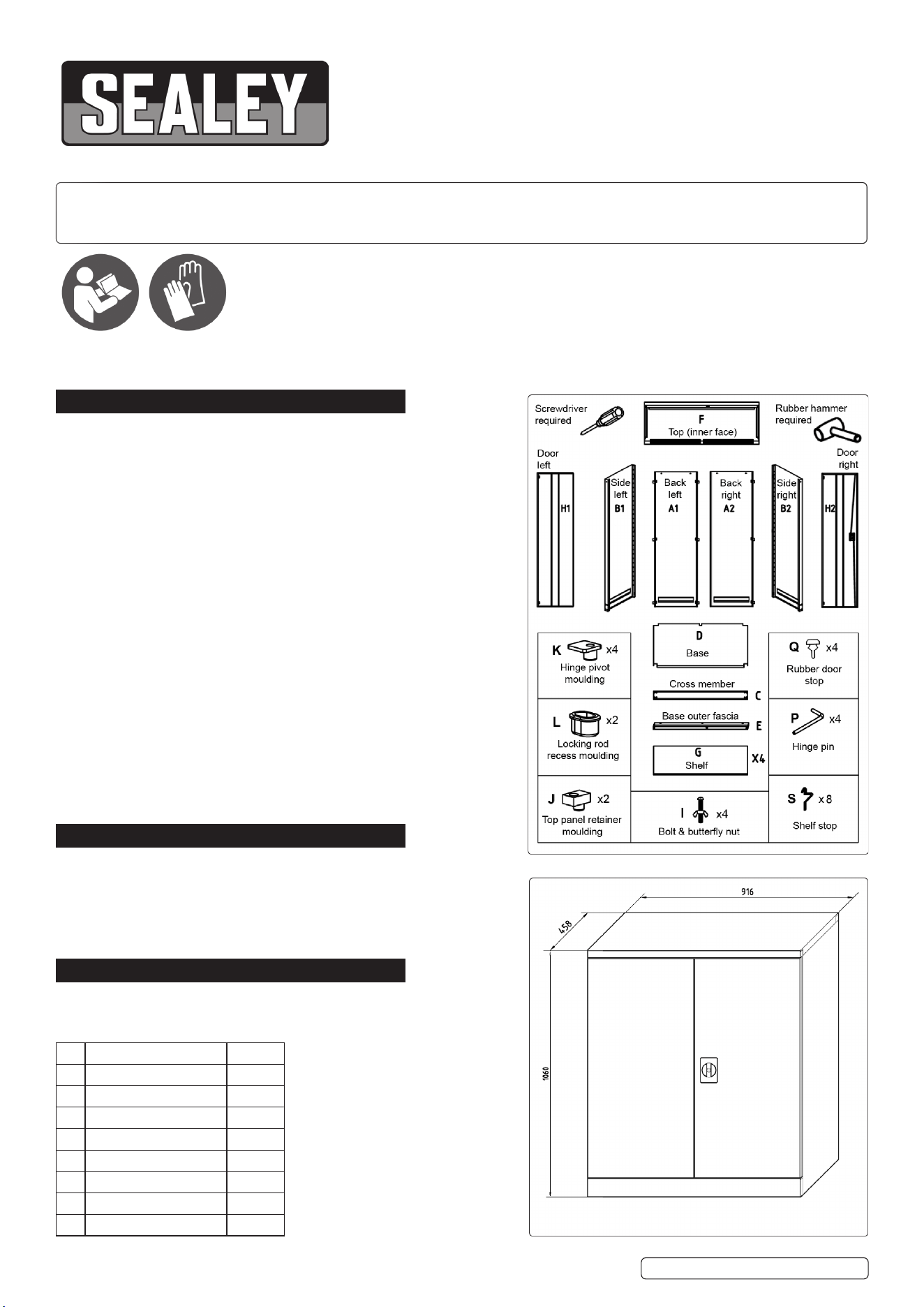
Size (W x D x H): 915 x 460 x 1060mm
3. CONTENTS
Unpack all the parts and layout on the packing material. Visually
inspect all panels to check for transportation
Damage.
Refer to
instruction
manual
SC03 Issue 2 (ALL) 17/10/23
Original Language Version
A1 Back (left hand side) X1
A2 Back (right hand side) X1
B1 Side (left hand side) X1
B2 Side (right hand side) X1
C Cross member X1
D Base X1
E Base outer fascia X1
F Top X1
G Shelf X4
Wear
protective
gloves
H1 Door (left hand side) 1 o
H2 Door (right hand side) 1 o
I Bolt and buttery nut 4 o
J Top panel retainer
moulding
2 o
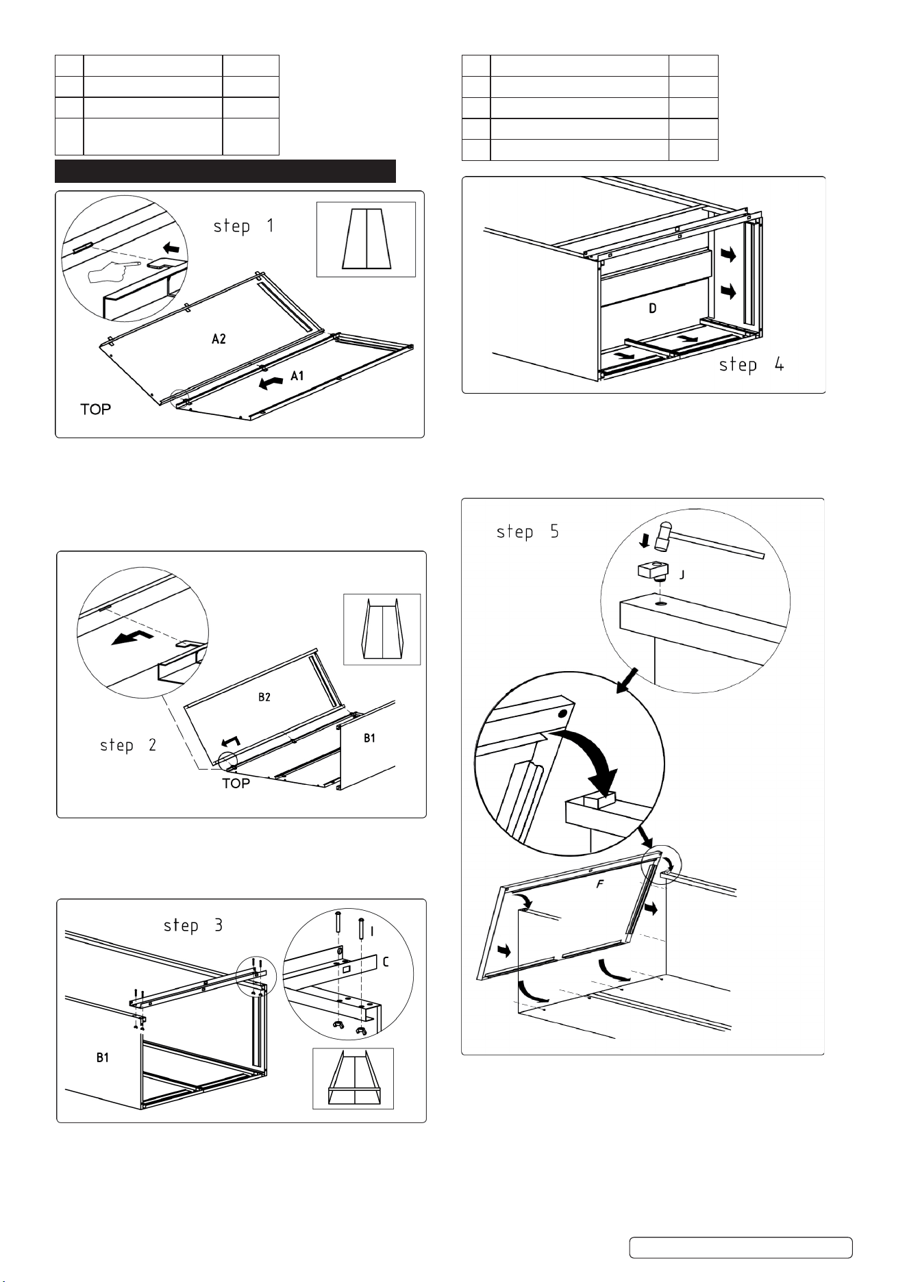
4. ASSEMBLY
4.1. BACK ASSEMBLY (Step 1)
4.1.1. Place the back panels (A1& A2) on a suitably protected
at surface to prevent scratching.
4.1.2. Interlock the tabs into the slots on the back panels and
slide together until the two panels are fully engaged and
aligned.
4.2. SIDE ASSEMBLY (Step 2)
4.2.1. Hold the side panels (B1 & B2) at a slight angle and t
the tabs on the back panels into the slots of the side
panels and slide up to engage.
4.3. CROSS MEMBER ASSEMBLY (Step 3)
4.3.1. Tie the side panels together at the bottom front edge by
attaching the cross member (C) using four bolts (I) and
four buttery nuts as shown in the inset diagram above.
4.4. BASE ASSEMBLY (Step 4)
4.4.1. Place the base (D) into position as shown above and slide
it down to the bottom until its edges make contact with the
receiving channels on the back and side panels. Using a
rubber hammer, tap the base down until it is fully engaged in
the channels.
4.5. TOP ASSEMBLY (Step 5)
4.5.1. Take the two top panel retainer mouldings (J) and fully insert
one into each hole at the top front edge of each side panel in
the orientation shown in Step 5.
4.5.2. Take the top panel (F) and hook it’s front edge over the two
retainer mouldings, then swing the panel downwards until
the top edges of the back and side panels begin to enter the
receiving channels within the top panel. Tap the top panel
down into position using a rubber hammer until the four
indents in the back panels clip into the matching holes in the
back receiving channels.
K Hinge pivot moulding 4 o
L Locking rod recess moulding 2 o
P Hinge pin 4 o
Q Door stop moulding 4 o
S Shelf stop 8 o
SC03 Issue 2 (ALL) 17/10/23
Original Language Version
© Jack Sealey Limited
SC03 Issue 2 (ALL) 17/10/23
Original Language Version
© Jack Sealey Limited
Sealey Group, Kempson Way, Suffolk Business Park, Bury St Edmunds, Suffolk. IP32 7AR
01284 757500 sales@sealey.co.uk www.sealey.co.uk
NOTE: It is our policy to continually improve products and as such we reserve the right to alter data, specications and component parts
without prior notice.
IMPORTANT: No Liability is accepted for incorrect use of this product.
WARRANTY: Guarantee is 12 months from purchase date, proof of which is required for any claim.
ENVIRONMENT PROTECTION
Recycle unwanted materials instead of disposing of them as waste. All tools, accessories and packaging should be
sorted, taken to a recycling centre and disposed of in a manner which is compatible with the environment. When
the product becomes completely unserviceable and requires disposal, drain any uids (if applicable) into approved
containers and dispose of the product and uids according to local regulations.
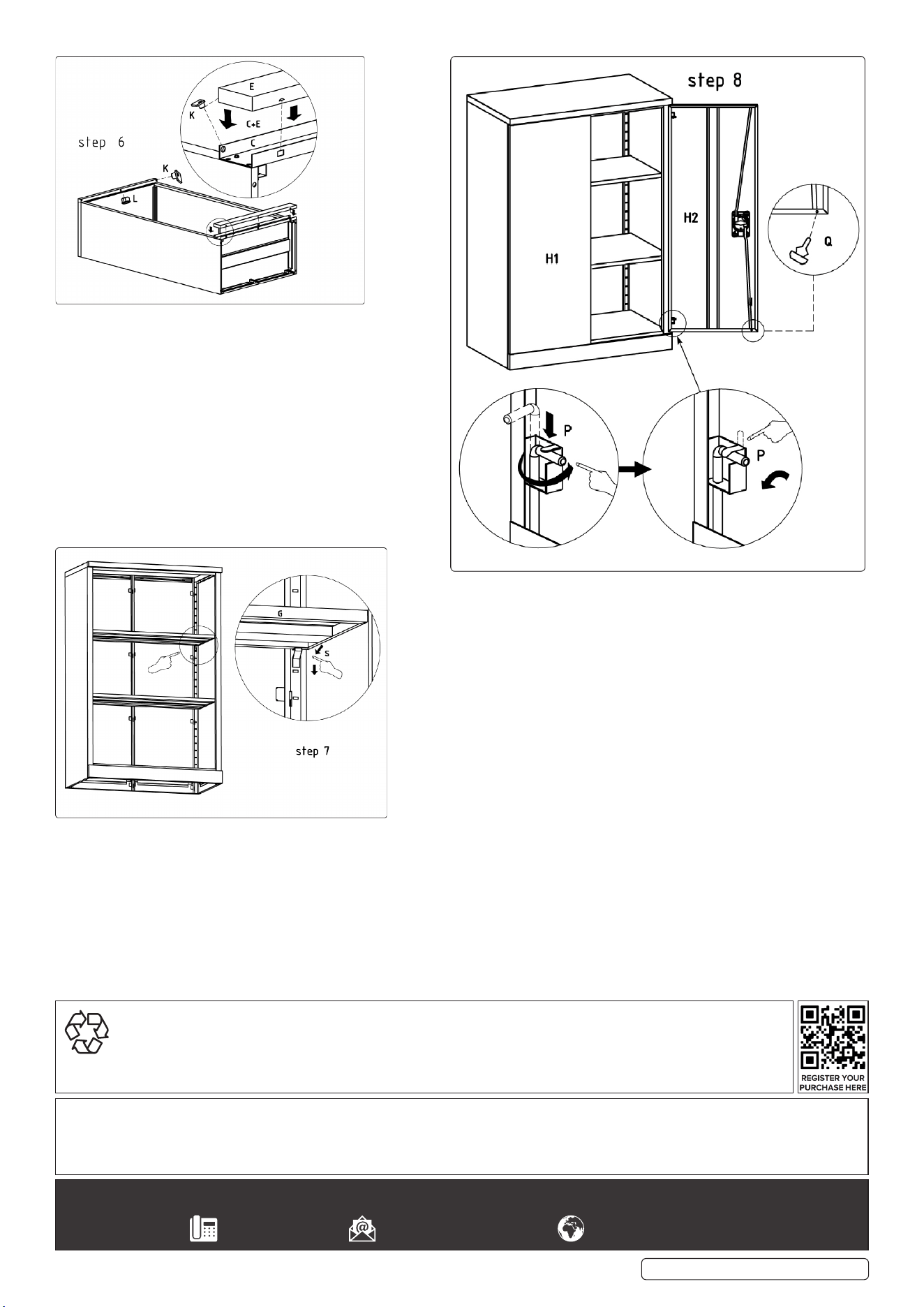
4.6. BASE OUTER FASCIA ASSEMBLY (Step 6)
4.6.1. Fit the base outer fascia (E) over the cross member
(C) with the hinge pivot holes facing upwards. Tap the
base outer fascia down with a rubber hammer until the
indents in the sides of the fascia clip into the matching
holes on the cross member (C).
4.6.2. Insert a hinge pivot moulding (K) at each end of the
upper face of the base outer fascia (E). Insert the
other two hinge pivot mouldings at each end of the
downward facing edge of the cabinet top.
4.6.3. Insert a locking rod recess moulding (L) into the
centrally placed holes in the same faces used for
mounting the hinge pivot mouldings at both the top
and the bottom.
4.7. SHELF ASSEMBLY (Step 7)
4.7.1. Insert shelf stops (S) at the desired height for each
shelf and lay the shelves onto the stops.
4.8. DOORS ASSEMBLY (Step 8)
4.8.1. Mount each door in turn by placing it between the upper and
lower hinge pivot mouldings. Align the upper hole in the door edge
with the hole in the upper pivot moulding and insert a hinge pin
upwards through the door and into the moulding. Rotate the short
arm of the pin around onto the inner face of the door as shown
above and bend over the metal tab to retain it. Mount the lower
hinge pin in the same way. Repeat the process to mount the other
door.
4.8.2. Fit the rubber door stops (Q) as shown in Step 8 to the corners of
each door.
4.9. Using a mild solution of detergent and water and wipe the unit
down with a soft cloth.