Loading ...
Loading ...
Loading ...

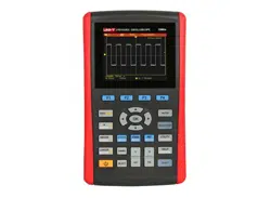
UTD1000L Us er M anual
Term Explanatio
n
Input Channel :
Trig ger Mode:
Auto:
Norm al
Single:
Trigger Couplin
g
DC:
HF Reject:
1 Trigger Source Input channel is used as the
trigger source
Input channel (CHI) is the most
commonly used trigger source. For the channel
selected as the trigger source, it should be
swit che d on bef ore it wor ks nor ma lly
.
2 decide what the oscilloscope will
do when no trigger event occurs. Three trigger
modes are offered : Auto, Normal and Single
The system automatically acquires data
even there is no signal input and therefore displays
scan reference line on the screen when the
trigger occurs it converted into trigger scannin
g
and synchronizes with the signal on it s ow
n
Note: The O scilloscope will go into SCAN mode if
waveform scan rate is set at 50ms/div or lower
timebase
Under this mode, the Oscilloscope
acquires the waveform only after the trigger
conditions are met. It stops to acquire and keeps
waiting if no signal is input O nce the trigger
occurs, the scan starts
.
YoujustneedtopressRUNbuttonif
under single mode then t he Oscilloscope waits
to trigger. It begins to acquire and display all
acquired waveforms once single-shot trigger signal
is detected, after that, it stops
.
3 Todecidetopasswhic
h
kind of components through the trigger circuits
The types include: DC, AC a
n
d Hf Reject
.
passes through all components of the
signal
A
C blocks DC component and attenuate
signals at 10H
z
attenuates high frequenc
y
component at 80kHz
˘
˚
Ŷ
Ŷ
Ŷ
Ŷ
Ŷ
Ŷ
Ŷ
Loading ...
Loading ...
Loading ...