
L

L

Preface
Dear users
:
Hello! Thanks for you choosing the brand new UNI-T device. In order to use the instrument correctly
,
please read the manual thoroughly and especially the Safety Notes part before using the device
.
If you have read through the manul, you are recommended to keep the menu properly with the instrument
together or at the place you can read anytime in order to read it in the process of future use
.

Content
s
Item
Chapter1 Safety Information............................................................... 1
General Safety O verview
Chapter2 UTD1000L Series Oscillosc ope Overview ....................
.
UTD1000L Series Oscilloscope Introduction ....................
.
UTD1000L Series Os cilloscope Accessories
UTD1000L Series O scilloscope Key Features
Safety Terms and Symbols..................................................
.
.................................................... .
.
..
.
......................
5
....................... 5
Chapter3 Connections to the Os cilloscope....................................... 6
General Check................................................................... 6
Checking for any damage due to the transit..........................
6
Checking the Accessories................................................. 6
Checking the Whole O scilloscope.....
.
...............................
7
Connection Interfaces........................................................ 7
Compensation Output Connection......................................
8
Front Panel and Keypad....................................................
.
Chapter 4 Using Basic Oscillos cope Functions................................... 1
2
A
bout the Chapter................................................................. 1
2
Powering on the Oscilloscope............................................. 1
2
8
Page
UTD1000L Us er Manual
1
4
4

Item
Hiding Menus
Making C onnections for Probe Compensatio
n
Compensating the Probe
Vertical System
.......................................................................
.
.... ............... ...
.............................................................. 1
2
....
.
....................................................................... 17
Horizontal System................................................................... 18
A
utoset for Waveform Display................................................. 1
9
Full Autoset for Input Signal................................................... 20
Run/Stop Data Acquisition.
.
.................................................... 21
Setting Frequency Counter.................................................... 2
2
A
djusting Screen Intensity..................................................... 2
2
Saving Bitmap..................................................... ................. 23
Using Online Help................................................................ 23
Setting Single Trigger .......................................................... 24
Setting Vertical Horizontal Systems and Trigger Lev el Man uall
y
&
Page
Resetting the Oscilloscope.............................................. 14
Describing the Display...................................................... 12
UTD1000L User Manual
Using Functional Menus.................................................. 14
1
5
1
5
1
7

Item
................................................ 24
Checking Oscilloscope System Information.........................
.
Making Auto Measurements................................................ 26
Measuring All parameters................................................... 26
........................ 29
................... 29
.................. 3
0
........................................................ 30
......................................... 31
...................................... 3
2
...............................
.
............................... 3
5
Connections to the Multimeter............................................ 3
5
Display Indicators................................................................ 3
5
Making Multimeter Measurements...................................... 36
Measuring Resistance......................................................... 36
Testing Diodes...................................................................
.
Using AVG Mode for Smoothing Waveforms
Using Peak Detect Mode f or Pulse Peak Displa
y
Observing Wavefor ms with use of Persistence
Selecting AC Couplin
g
Inverting t he Waveform Displa
y
A
utoset for Signals with DC Offset
.
A
bout the Chapter
Page
Chapter 5 U sing the Multime te
r
.................................................... 3
5
UTD1000L Us er Manual
Viewing Oscilloscope Sta tus
2
6
3
7

Item
Measuring DC Voltage
Measuring AC Voltage
Measuring DC Current with UTD1000CL
Measuring AC Current with UTD1000CL
Measuring DC Current with UTD1000DL
Measuring AC C urrent with UTD1000DL
Data Hol
d
Making Relative Measurement
Selecting Auto Manual Rangin
g
Chapter 6 Using the Oscilloscope i n Details
Setting Vertical System
.......................................................... 3
8
......................................................... 3
9
............................. 3
9
............................. 41
............................. 4
3
................................ 47
............................................................................. 51
.............................................. 51
.......................................... 5
2
...................................... 5
3
A
bout the Chapter...........................
.
.................................... 5
3
....................................................... 5
3
UTD1000CL Channel Setup................................................ 53
UTD1000DL Channel Setup................................................ 56
Setting Probe Factor........................................................... 5
9
Page
Measuring Capacitance.................................................. 3
8
Testing for Continuity...................................................... 37
UTD1000L User Manual

Item
Setting Horizontal System.................................................... 5
9
.............................................................
.
............................................. 5
9
................................................ 60
................................................... 61
........................................................ 6
2
.................................................................. 64
........................................................................ 6
5
..........
.
................................................... 6
6
....................................................................... 67
....................................................................... 6
8
.................................................... 71
.............................................................. 7
2
............................................... 74
...................................................... 80
Changing Timebase
Moving Waveforms Horizontall
y
Zooming in out Waveforms
A
djusting Trigger Hold Off
Setting Tr igger System
Common Settin
g
Edge Trigger
Pulse Width Trigger
Video Trigger
Slope Trigger
Setting Acquisition Mode
Setting the D ispla
y
Setting Auto Measurements
Recording and Storage
Page
UTD1000L Us er Manual
5
9

Item
Recordin
g
Recallin
g
Making Cursor Measurements
Interface Setup
Utility Setup
Executing Mathematic Functions
A
utoset
Chapter 7 Tr oubleshootin
g
The Oscilloscope turns off just a few seconds later after
powered o
n
............................................................................. 80
Storage................................................................................ 83
.............................................................................. 84
.............................................
.
...................................................................
.
......................................................................... 8
9
......................................... 91
...................
.
............................................................ 9
6
............................................................... 97
...... .... .... ..... .... .... ..... .... .... 9
7
...... .... .... ..... .... .... .... ..... .... .... .. ..... .... .... ..... .... .... ... 9 7
....... .... .... ..... .... .... ..... .... .... .... ... .... .... .... ..... .... .... ... 9 7
.............................. 97
The Oscilloscope cannot power o
n
Measuring voltage amplitude is 10 times larger or smaller tha
n
exac tv alue
No waveform displays after acquiring signals
Page
UTD1000L User Manual
8
8
8
6

Item
The waveform does not display steadily................................ 97
................. 9
8
.......................................................... 9
9
............................................................... 9
9
................................................. 9
9
............................................................... 9
9
................................................................. 9
9
...................................................................... 10
2
.................................
10
2
.................................................. 11
There is no d is p lay after p res s ing down R UN STOP button. ... .
.
The display slows down after having applied AVG mode for a while
.
The waveform display has a stair-stepping shape
Chapter 8 S ervice and Suppor
Updating Program
Preparations before Update
Update Conditions
Program Update
Chapter 9 Appendixes
A
ppendixA Technical Specifications
A
ppendix B Maintenance
.
1
Page
UTD1000L Us er Manual
9
8
9
8

Chapter 1 Safety Informatio
n
Safety Terms and Symbols
Terms in the manual
Wa rning:
Caution:
Te rms on the produc t
DANGER
WARNING
CAUTION
Symb ols on the pro duct
Symbols on the product
Following terms may appear in this manual
:
a Warning specifies conditions and
actions that may pose hazards to the user
.
a Caution identifies conditions and
actions that may cause damage to the product
or other properties
Following terms may show on the product
:
indicates any injury hazard
immediately accessible as you read the marking
.
indicates any injury hazard not
immediately accessible as you read the
markin
g
indicates any damage may happen to
the product or other properties
Following symbols may show on the product
:
The following symbols might be on the product
:
Refer to the manual
High Voltage
Measuring Groun
d
Terminal
UTD1000L User Manual

General Safety Overview
The oscilloscope is strictly designed and
manufactu red as per safety/compliances: GB479
3
IEC61010-1, Overvoltage CAT
V and Pollution Degree I
I
Please review following safety precautions to avoid
personal injury or any damage to this product or
any products connected to it. Operate the product
as specified to prevent any potential hazards. Onl
y
the qualified personnel can perform the servicin
g
procedures
.
Use only the insulated voltage probe, test leads
and power adaptor supplied or specified by UNI-
T for this O scilloscope Series
.
Please check multimeter test leads, oscilloscope
probe and other accessories for an
y
mechanical damage Please make the
replacement if any damage is found
.
Remove all unused test leads, probe and other
accessories.
Insert the power adaptor first into AC socket
before connecting it to the O scilloscope
Do not input voltages higher than 300V into
scope terminals under CAT II measurin
g
environment working voltage applied into
multimeter terminals must not exceed V
under CAT measuring environment
.
Do not apply working voltage higher than rated
values on the Oscilloscope
ċ
Warning: To avoid electric shock or fire, use
only the po wer adaptor specified for th e
Oscillos cope and c ertified for the power grid b
y
the country o f use.
Warning: If the O scillo scope termina ls are input
with voltages higher than 42V (30 Vrms) to
avo id pers ona l elect ri c shock
II
I
safety requirements for electronic measurin
g
instruments
,
UTD1000L Us er Manual

UTD1000L User M anua l
Use only the accessories supplied for the
Oscilloscope do not use them if any damages
are found
.
Do not plug any metal object into the connectors
Use the Oscilloscope as specified
.
Rated voltage value mentioned in Warnin
g
is the working voltage limit for the power
adaptor It represents Vrms 50-60Hz) w he
n
applying AC sinewave
To av oid fir e or
electric hazard, please observe all ratings and
symbols on the Oscillosc ope. Read through the
manual for details before making connections to
the Oscilloscope
Please
have it checked by qualified servicing staff if you
doubt the product does not work normally
.
Āā
Āā
Only q ualified staff can perform the servicin g.
Check all terminals ratings:
Do not o perate w ith suspected failure:
Do not operate in d amp environment.
Do not operate in explosive environment
Keep the product surface clean and dr
y

UTD1000L Us er Manual
Chapter 2 UTD1000L Serie
s
Oscilloscope Overview
UTD1000L Seri es Os cilloscope
Introductio
n
UTD1000L Handheld Digital Storage
Oscilloscope Hereinafter referred to as The
Oscilloscope combines digital scope and
multimeter functions just into one tool. The ease-
of-use feature, excellent technical indicators and
multi-functions offered the O scilloscope can get
your work done much faster
.
The series offers four models for your option
:
UTD1000L Series Oscilloscopes o ffer users a
simple and clear front panel that helps to perform
primary operat ions a design you often get used
to and can save you a great amount of time to
learn about the Oscilloscope In order to speed
up calibrati
ons and measurements, pressing AUTO
button can make the oscilloscope display proper
waveforms and settings directly. Meanwhile the
Oscilloscope offers SHIFT button to combine with
other buttons to further operate the menus
much easier Beside ease of use, this series
outstands itself with superb performance and
powerful functions, such as remarkable trigger and
analysis ability, making it easy to capture and
analyze the waveforms high definition Displa
y
and math function, ensuring a very clear and
fast view on waveforms and finding out the signal
problem
Ā
ā
Type
Bandwidt
h
Samplin
g
velocit
y
Channel
count
Single channel
Single channel
Dual Channel
Dual Channel
UTD1025C
L
UTD1050C
L
UTD1025D
L
UTD1050D
L
25MH
z
50MH
z
25MH
z
50MH
z
200MS/s
200MS/s
250MS/s
250MS/s

UTD1000L Series Oscilloscope Accessories
Unpack the carton and you will see followin
g
accessories should be included
UTD1000L Seri es Os cilloscope Ke
y
Features
Scope
Totally Auto Scale
Unique and powerful A uto Setup,
Wider voltage measuring range
Isolated USB
Colo
r
Intelligent local or n etwork software
Unique waveform record, storage and recall
High-r esolutio n an d high-contras t c olor LCD
h
Vert ic al Scal e and
Timebase automatically adjusted with the signal
and without any manual interference
quic k a n
d
accurate to set up for signals with any D
C
component
Coupled wit
h
10 probe with attenuation up to 200V/di
v
for much safer communication
White black display for your optio
n
perf ect fo r use outd oor s with st rong s unsh ine
.
update
functions
UTD1000L User M anua l
No.
1
2
3
4
6
5
7
8
9
1
0
Instructio
n
UNI-T oscilloscope
Power Adaptor, 1 pc
UTD1000CL Standard Probe, pc
UTD1000DL Standard Probe pcs
1
2
Multimeter Test Leads, 2pcs
one red, one black
Operating Manual pc1
UTD1000CL standard UT-M07 10
A
current divider module pcs
UTD1000DL standard UT-M04 4
A
current divider module pc UT-M1
0
mA current module pc
1
1
1
CD (for communication software
between PC and the Oscilloscope), 1pc
carrying bag, 1pc
Oscilloscope probe adjusting tool, 1pc
USB wire pc1
Standar
d
configura tion

UTD1000L User M anual
8 hours of contin uous battery operation fo
r
UTD1000CL and 6 hours for UTD1000DL
UTD1000CL 19 types of auto measurements
UTD1000D L 22 types of auto measurements
Simple Printscreen function
Multilingual help information
Multimete
r
3999 display count
Voltage, current, resistance, diode,
capacitance, continuity measurements
offere
d
Measure current up to 10A UTD1000DL 4
A
max
Extremely low internal resistance designe
d
for cur rent measurement e nsurin g bette
r
measuring accurac
y
Indepen dent multimeter and scope functions
in on e tool
Checking for any damage due to the transit
Checki
ng the Accessories
Ā
ā
Ɣ
Ɣ
Chapter 3 Oscilloscope
Connectio
n
General Check
It is r ecommended that you should proceed
following inspections when you get a new UT1000L
series oscilloscope
Co ntact U NI- T de al ersh ip or loc al UN I-T office
immediately if the packing carton or foamed
plastic cushion is seriously damaged
The accessories supplied for the Oscilloscope
are listed in the section UTD1000L Series
Oscilloscope Accessories hereinbefore. Please
refer to the section and check if any accessory is
missing
.
Please contact UNI-T dealership or local UNI-T
office if there is any damage or missing item
.

UTD1000L User M anua l
Checking the Whole Oscilloscope
Oscilloscope Connections
If the Oscilloscope is found damaged
externally or it does not work normally or pass
any performance test, contact our UNI-T
dealership or local UNI-T office
If the product is damaged due to the transit
keep the package and inform the shippin
g
agency and UNI T dealership, UNI-T will
arrange the maintenance or replacement for you
.
See Figure 3-1 for the Os cilloscope
connection interfaces
Connection Interfaces
Figure 3-1 Oscilloscope C onnection Interfaces
5
6

UTD1000L Us er M anual
Descri ption:
1 Input terminals for scope channels
2 USB Connection port
3 The port to connect power adaptor for AC power
supply and battery charge
.
4 Output terminal for probe compensatio
n
5 UTD1000CL multimeter input terminals
6. UTD1000DL multimeter input terminals
Connect to the output 1kHz 3V terminal as
shown below for the Oscilloscope probe
compensatio
n
Learn about the Oscilloscope front panel and
buttons shown in Figure 3-3
:
Compensation Output Connectio
n
Front Panel a nd Keypa
d
Picture Compensation Signal Output
Connection of the Apparatus
3-
2
Figure 3 3 UTD1000L Series Front Panel

To power on off the Oscilloscope
To set up the submenus
To toggle between Scope (DSO) and
multimeter (DMM) modes
Press this button to access ACQUIRE
(sample mode)menu if under DSO mode
press SHIFT first and then this button to
access intensity, with help of right and left
arrow buttons, you can change scree
n
brightness. If under D MM mode pressin
g
this button can access voltage
measurement men
u
: Press t his button to access DISPLA
Y
(Display mode) menu if under DSO mode
or press SHIFT first and then this button to
access CONFIGURE interface
configuration menu pressing this butto
n
under DMM mode to access current
measurement men
u
Press this button under DSO mode to
access MEASURE auto measurement
menu or press SHIFT first and then the
button to access COURSOR cursor
measurement)menu if under DMM
mode press the button to access
resistance measurement menu and
measure resistance diode continuity/
capacitance
: In DSO mode press it to access
CHANNEL menu for UTD1000CL
repeatedly press to toggle between two
channel menus for UTD1000DL
In DSO mode, press the button to access
FFT menu for UTD1000CL or press the
button and then F1 button to toggle between
FFT and MATH menus for UTD1000DL
Pre
ss SHIFT first and then the button to
access STATUS display
F1 F
4
UTD1000L User M anua l

In DSO mode, press to access RECORD
(waveform record) menu or press SHIFT
firstandthenthebuttontoaccess
STORAGE men
u
Under DSO mode, press to set up
SINGLE single trigger function press
first SHIFT andthenthebuttontoaccess
REF waveform recall) menu
.
Under DSO mode, press to automaticall
y
set up the waveform press SH IFT first
andthenthebuttontoswitchonfull
autoset function The O scilloscope ca
n
aut oma tic ally ad jus t the ran ges to o btai
n
optimal waveform based on the input
signal without any manual interference
: Under DSO mode, press to start/stop data
acquisition if under DMM press the
button to lock measuring readings o
n
the scree
n
Under DSO mode, press to access
TRIGGER menu or press SHIFT first and
then the button to access UTILITY menu
Under DSO mode, press to access
HORIZONTAL menu or press SHIFT
first and then the button to open HEL
P
information
Combine with other buttons to select
func ti on opti on s
Timebase: To change scan rate, rangin
g
from 50s/div 10ns/div for 25MH
z
bandwidth models and 50s/div 5ns/di
v
for 50MHz bandwidth models and
stepping in 1-2-5 Press s to access
relatively slower scan rate or ns to
speed up
Vertical Scale: To change vertical scaling
,
ra
n
ging from 5mV/div 20V/div and
stepping in 1-2-5 Press V to zoom
in current vertical scale or mV to
zoom out
Āā
Āā
Āā
Āā
:
:
UTD1000L Us er M anual
RUN/STOP
SHIFT
n
s

UTD1000L Us er M anual
: To toggle between vertical position and
trigger level if vertical position is
choosen vertical reference cursor
turns solid then you can move
waveforms vertically with Up and Dow
n
buttons. Press SELECT again to make
trigger level cursor solid, and also use Up
and Down buttons to adjust trigger point
location Under MEASURE menu, this
button is used to confirm selected
parameters, or it is to toggle betwee
n
Cursor 1 2 under cursor measurement
.
A
rrow and OK buttons OK button is
used to hide display current menu
under DMM mode it is used to
confirm if current divider has bee
n
properly connected w
h
en making
A
current measurement
To save current interface into
internal memory which can be
exported externally b PC whic
h
has been loaded with the
Oscilloscope software
to open full autoset function i
n
which the O scilloscope ca
n
automatically adjust vertical
scale and horizontal timebase
based on the input signal so that
the optimal waveform can be
obtained without any manual
operation
.
To open main trigger
men
u
Shortcut Buttons Description:
SHIFT OK
y
SHIFT AUT
O
SHIFTF1F2F3F4

Chapter 4 Using Basi
c
Oscilloscope Functions
About the Chapte
r
Powering on the Oscilloscope
This chapter only briefs users on basic functions of
the Oscilloscope for example how to use
menus and execute basic operations not a
step by st ep in trod uct io n on all func ti ons
UTD1000L Series can be powered by the
battery and power adaptor. The power suppl
y
voltage from the adaptor is DC9V/1.5A To
operate the Oscilloscope normally please use
the power adaptor specified for the Oscilloscope
Press Power button and SHIFT light illuminates
for 3 seconds, then the Oscilloscope logo appears
,
indicating the Oscilloscope has already turned
on
.
Figur e 4-1 Dis play In ter face
Besides the waveform, there are still a lot of details
about the waveform and oscilloscope control
settings on the screen
:
1 Trigger source status
:
CH1 CH2 : indi cate s y ou can adj ust the
waveform of this channel
Describi ng the Displa y
UTD1000L Us er M anual

UTD1000L User M anua l
REF: indicates you can adjust the recalled
wavefo rm
FFT: indicates you can execute FFT operatio
n
on the waveform
2 Trigger couplin
g
A
C ac couple
d
DC dc couple
d
HF high frequency reject
3. Trigger level readout
4. Trigger status
:
A
RMED The Oscilloscope is acquiring all pre-
trigger data and ignores all trigger events
READY The Oscilloscope has acquired all
pretrigger data and is ready to trigger
TRIG E D The Osc illo sco pe has d ete cte d out
one trigger and is acquiring posttrigger data
STOP The Oscilloscope has stopped acquirin
g
wavefo rms
A
UTO The Oscilloscope is in auto mode and
acquires waveforms without trigger
SCAN The Oscilloscope continuousl
y
acquires and displays waveforms under sca
n
mode.
5. The time readout that indicates how far the
trigger point is from the central point
6. The power supply indicator
:
The Oscilloscope is powered by the batter
y
The Oscilloscope is powered by DC power
adaptor.
7. The marker for ground reference point for
displayed waveforms
8. 1 indicates probe attenuation factor for the
channel is 1
9. The readout for main timebase settin
g
10 Connected to PC ico
n
11 Readout for the current vertical scale factor
12 Waveform Invert Indicator that indicates that
the waveform is reversely displayed horizontal
midline
.
13 Position readout from the channel reference
marker to the horizontal line on the scree
n
h
h
Ā ā

Resetting the Oscilloscope
To r eset the Oscilloscope to the default, do the
followin
g
1 Press SHIFT button, shift icon displays o
n
the upper right corner of the scree
n
2 Press UTILITY button and four options shows
on the bottom displa
y
3 Press F2 button to select the default setup. The
n
the Oscilloscope is set to the default settings
The Default setup is as follows
:
The procedures below show you how to select
functions with use of oscilloscope menus
1. Press any functional button on the keypad, then
corresponding options will show on the bottom
display, you can select one of these options wit
h
use of F1 F4 After that, press OK button t
o
hide functional menus
Āā
a
Note:Pressinguparrow buttoncanalsosetthe
Oscilloscope to the default when powering on.
Using Functiona l Menu s
UTD1000L Us er M anual
Figure 4-2 Default Setup
Function
s
SEC/DIV
A
cquire Mode
VOLT/DIV
Trigger Couplin
g
Channel Status
Trigger Mode
Display Format
Persist Time
Display Style
Manual Displa
y
Default Setup
Norma
1ms/di
v
100mV/di
v
D
C
CH2 Off (1000DL series
A
ut
o
Vector
A
ut
o
Classic
Manual

2. For the buttons printed with multiple functions, if
you want t o choose one of these functions, please
press SHIFT button first, accompanied by shift
icon on upper right corner of display, then press the
corresponding button to obtain the function you
want
.
Press down OK button to hide all button icons and
menus. To display menus or button icons, press OK
agai
n
Figure 4-3 Hiding Menus
Connect the signal as follows
:
1. Connect the probe connector to the
Oscilloscope input terminal and switch probe
factor to 10 on the probe
2. You also need to set up probe factor on the
Oscilloscope this factor changes vertical scale
h
Hiding Menus
Making Connections for Probe
Compensatio
n
Note: To set up auto hiding ti me for menus
please find correspond ing opti on in
CONFI GURE menu
UTD1000
L
User Manual

UTD1000L Us er M anual
and ensures the accuracy for measurements To
set up the probe factor on the Osciloscope
pres s CHA NNEL bu tton th en F3 t o set pro be
fact or to1
0
3. Conenct the probe to the output terminal for
probe compensation on the Oscilloscope, press
A
UTObutton, after several seconds, squarewave
displays 1kHz 3Vpp Peak to Peak Value
SeeFigure4-5
.
You need to compensate the probe whenever
connecting it to channels for the first time so as
to match the probe to the input channel
Uncompensated probe may cause deviation or
error to the measurement. To compensate the
probe, do the following
1. First of all, set probe factor on the Oscilloscope
to10 turntheswitchto10 ontheprobe
h
h h
Compensating the Probe
Figure 4 Adjusting Probe Factor-
4
Figure Squarewave Signal from the Oscilloscope Itself4-
5

UTD1000L User M anua l
then connect the probe connector to the
oscilloscope input channel and the probe tip to
compensation output terminal
2. Then execute AUTO
3. Observe the displayed waveform
If the displayed waveform is under-or over-
compensate d as indicated above, use the adjustin
g
tool with non-metal handle to adjust the variable
capacitor on the probe until correctly compensated
waveform shows
To avoid any electric shock whe
n
measuring the high voltage with use of the probe
,
please ensure the probe wire is perfectly insulated
,
and do not touch any metal part of the probe while
connecting to the high voltage source
.
Pre ss V mV button s to adj ust the v erti cal
scal e(VO LT/DI V) and displ ay wav efo rm with pro per
size on the scree
n
When channel cursor turns solid press Up
and Down button to adjust ground reference
point that can allow the waveform to display at
proper locatio
n
Wa rning:
Ver tica l Syst em
Setting Vertical&Horiz ontal System s
and Trigger Level Manuall
y
Over compensation
correct compensation
under compensation

Figure 4-6 Moving Waveforms Verticall
y
Note: Use SELECT button to toggle betwee
n
vertical position and trigger level
Press down s ns buttons to change the timebase
and the timebase readout in status bar will var
y
accordingly The horizontal scan rate ranges from
5ns 50s/div 10 ns 50s/div for 25MHz bandwidth
models) and steps in 1 2
5
Press Right and Left arrow buttons to adjust the
horizontal location of the trigger point which can
allows to observe more pretrigger data
ˉ
ˉ
Horizontal System
UTD1000L Us er Manual
Figure 4-7 Adjusting Horizontal Timebase

Trigger Level Autoset for Waveform Displa
y
ı
˚λ
When trigger level cursor turns solid use Up
and Down arrow buttons to adjust trigger level
locatio
n
Note: Use SELECT button to toggle betwee
n
vertical position and trigger level for the channel
.
Following chapter will offer more details about
the operation mentioned above
UTD1000L Series is designed with autoset
function that can automatically adjust the vertical
scale, scan timebase and trigger mode based o
n
the input signal until the optimal waveform can be
obtained. To apply the autoset function, the tested
signal should have a frequency at 20Hz and
duty cycle 1
Under AUTOSET mode, t
h
ecouplingmodeof
the channel is closely connected to DC autoset
When DC autset is set to off all signals in the
channel is AC coupled If DC autoset is on, the
channel will choose the current setting as coupling
mode, when the current setting is DC coupling, the
signal will be DC-coupled and vice versa
.
For example:
1. Input 1kHz 2Vpp sine signal into two
channels set coupling mode for both channels
to DC press Shift+UTILITY and then F3 to set
UTD1000L User M anua l
Figure 4-8 Adjust Trigger Level
UTD1000L User M anua l
set DC autoset to off. If AUTOSET is applied, the
coup ling m ode is swit che d to AC mo de
.
2. Input 1kHz 2Vpp sine signal into two
channels then set AC coupling for one channel
and DC mode to the other When AUTOSET is
applied the coupling modes for both channels
keep unchanged
UTD1000L can offer creative auto function to
capture input signal With this function applied
,
the Oscilloscope varies ranges accordingly based
on the input signal until the p roper waveform
display can be obtained without any manual
interference
.
To perform autoset function, do the followin
g
1. Press SHIFT button, the shift icon shows o
n
upper right corner of the scree
n
2. Press AUTO button when A icon displays o
n
the screen, autoset function has already turned o
n
When the model is UTD1000DL and both of
its two channels have signals, the signal from the
trigger source channel will be automaticall
y
displayed and the other channel will turn off
under autoset mode if there is only one
channel input with signals this channel signal
will be automatically selected and displayed no
matter w hich channel has been choosen as the
trigger source
.
Full A utoset fo r I nput Si gnal
Note:
Figure 4-9 Full Autoset

UTD1000L User M anua l
N o t e : Run/Stop Data Acquisi tion
1. Under autoset mode trigger mode is set to
A
uto and cannot change
2. Once you are in autoset mode followin
g
settings are forced to execute
1 The Oscilloscope will sw itch into mai
n
timebase status if the current display isn t under
this status
2 The coupling mode will be set to A
C
mode and allows no change
3. Any adjustment on the vertical scale or
horizontal timebase of the Oscilloscope that has
changed waveform vertical or horizontal locatio
n
will make the Oscilloscope automatically exit
autoset mode
To stop the data acquisitio
n
1. Press RUN/STOP button, the Oscilloscope
stops data acquisition and STOP indicates o
n
the upper displa
y
2. Repress RUN/STOP then the oscilloscope
will restart t he acquisitio
n
Āā
Figure 4-10 Stop Data Acquisitio
n

UTD1000L Us er M anual
Setting Frequency Counte
r
Note:
Adj usti ng Scr een In ten sit
y
Note:
Āā
To switch on the frequency counter in models
suc h as UTD 1 000C L d o the follow in
g
1. Press SHIFT button, and shift icon shows o
n
upper right corner of scree
n
2. Press UTILITY button to display utility menu
3. Press F3 button to set the frequency counter to
O
n
The frequency counter of UTD1000DL
defaults at On status
To adjust the intensity of the screen d o the
followin
g
1. Pr ess S H IFT button, a nd shift ic on s ho ws o
n
upp er r ig ht corner of s c r ee
n
2. Press ACQUIRE button and select backlight
menu
3. Press F1 to switch on backlight intensity bar
4. Press Left and Right arrow buttons to adjust the
intensity to proper value
5. Pre s s F1 to switc h o ff the b ac kl ig ht inte ns i ty bar.
Press down AUTO button, the backlight
intensit y b ar will switch off automatically
.
Figure 4-11 1000CL Trigger Frequency Counter

UTD1000L User M anua l
Saving Bitmap
Note:
Using Onl ine H elp
To save bitmap do the followin
g
1. Press SHIFT ,and shift icon shows on upper
right corner of scree
n
2. Press OK button, bitmap then will immediatel
y
be saved to the internal memor
y
through control software loaded in PC, the
bitmaps can be exported to PC in BMP format and
besavedupto10sets
.
To use built-in help information do the followin
g
1. Press SHIFT and shift icon shows on the
right corner of scree
n
2. Press HELP button, H icon shows on the upper
display, indicating Help function has a lready turned
o
n
3. Then you can press corresponding menu
buttons to check detail infor matio
n
4 To turn off this function, repeat Step1 and
2
Figure 4-12 Adjusting Backlight Intensit
y

UTD1000L User Manual
Setting Si ngle Trigger
To set trigger mode to Single directly do the
followin
g
1. Press SINGLE button, the Oscilloscope will be
set under single trigger mode immediately
.
Figu re 4-1 3 He lp Sy ste m
Figure 4-14 Single Trigger

UTD1000L User M anua l
Viewing Oscilloscope Status
Note:
To view the current status of the Oscilloscope do
the followin
g
1. Press SHIFT button and shift icon shows o
n
upper right corner of scree
n
2. Press STATUS button, current settings of the
Oscilloscope will be displayed on the scree
n
3. To turn off the information repeat Step 1 and
2
Press down AUTO button, status informatio
n
will then automatically turn off
Figure 4-15B UTD1000DL Status Informatio
n
Figure 4 A UTD1000CL Status Informatio
n
1
5

UTD1000L User Manual
Chec king Os cill os cope Sy stem I nfor mati on
Making Auto Measurements
To check the system configuration o f the
Oscilloscope do the followin
g
1. Press SHIFT and shift icon shows on upper
right corner of scree
n
2. Press CONFIGURE button to switch on displa
y
configuration men
u
3. Press F4 button, then details such as
oscilloscope model, version will show on the
scree
n
4. Press F1 button to switch off the displayed
window
.
There are two kinds of auto measurements
available in the Oscilloscope Measure all or
customized parameters. Maximum 4 parameters
can be selected if you want to customize your
own measurements
Figure 4-16 System Informatio
n

UTD1000L User M anua l
Measuring All Parameter
s
Note:
To measure automatically all parameters do the
followin
g
1 Press MEASURE button to displa
y
measurement men
u
2 For UTD1000CL press F1 button press F
2
for UTD1000DL then the screen will show
measurement results for all parameters
1) Switching between different signal sources i
n
UTD1000DL will change the paramteters
accordingly for channels
2) If the signal is input into only one channel of
UTD1000DL the rise delay fall delay and
phase parameter s will not be measured whe
n
this channel is choosen as the signal source
or the signal source is set to the channel without
signal input, no parameter measurement will be
made
.
Figure 4 A UTD1000CL measures all parameters
1
7
Figure 4 UTD1000DL measures all parameters B1
7

UTD1000L Us er M anual
Measuring Customized Parameters
Note:
To measure customized parameters do the
followin
g
1 Press MEASURE button to displa
y
measurement men
u
2 For UTD1000CL press F2 button F3 for
UTD1000DL t he screen will displa
y
measurement paremeters available for your
selectio
n
3 Press Arrow Buttons to select the desired
parameters, indicated in different color
4 Press SELECT button to confirm, the selected
parameter will automatically show on the screen
.
You can select up to 4 parameters
.
5. To turn off the menu p ress F2 i
n
UTD1000CL for F3 in UTD1000DL
For UTD1000DL use F1 to select signal
source to be measured
Figure 4 A UTD CL Customized Measurement
18 1000
Figure 4-18B UTD1000DL Customized Measurement

UTD1000L User M anua l
Using Using Peak Detect Mode for Pulse Peak Displa
y
A
VG mode for Smoothing Waveforms
To smooth t he waveforms do the followin
g
1 Press ACQUIR button to display sample mode
2 Press F1 button to set sample mode t o AVG
3 Pr es s L ef t and Righ t arro w but ton s to s et AVG
number t o 16 Then measurement results will
show after the O scilloscope has averaged the d ata
for 16 times
.
Thisfunctioncanbeusedtodisplaywaveformsat
50 ns or wider Pulse Peak or other
asynchronous waveform)
.
1. Press ACQUIR button to display sample mode
menu
2. Press F1 button to set sample mode to Peak
Detect
.
Figure 4-19 Smoothing with 16 times AVG Mode
Figure 4-20 Sampling with Peak Detect Mode

UTD1000L User M anua l
Observing Waveforms with use of Persistence Selecting AC Coupl ing
Select the Persistence function if you w ant to
observe continuously the dynamic signals
.
1 Press DISPLAY button to show Display Mode
men
u
2 Keep pressing F4 button to select betwee
n
1sec, 3sec, 5sec, Infinite or Auto options If
display mode is set to Infinite dynamic signals
will be kept on the screen When set to Auto
the Persistence function will turn on accordingly
.
The sc reen di spl ays bot h AC and DC v olt age s i f the
oscilloscope is set under DC coupling. If only the
small AC signal mixed in t he DC signal is expected
to display, please select AC coupling mode
.
To select AC coupling d o the followi
n
g
1. Press CHANNEL button to display Channel
menu
2. Press F1 button( F2 for UTD1000DL to set
CouplingtoA
C
Figure 4-21 Persistent Display for Seconds3
Figure 4 A UTD1000CL AC Couplin
g
2
2
UTD1000L User M anua l
Figure 4-22B UTD1000DL AC Couplin
g
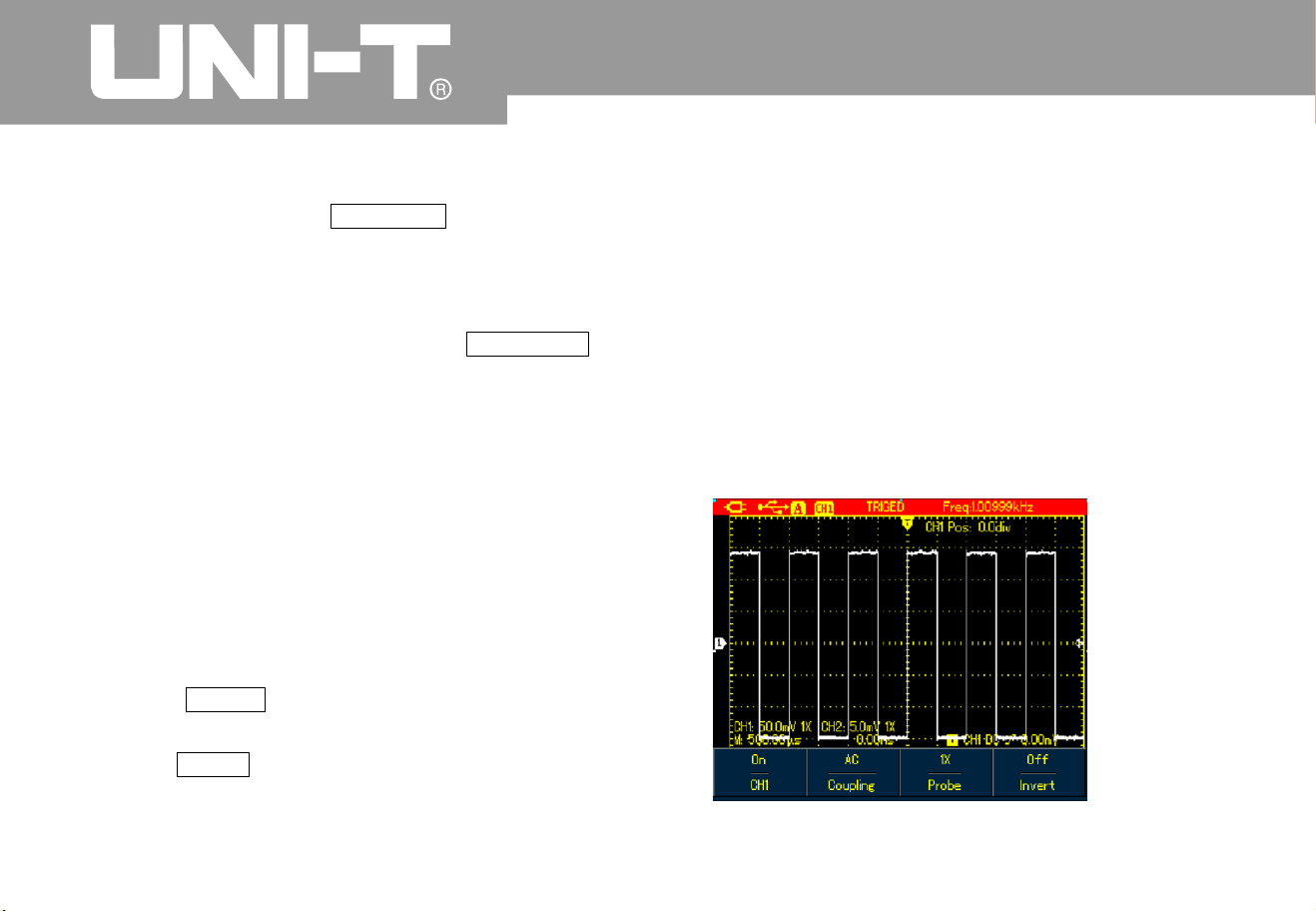
To invert the waveform on the display do the
followin
g
1. Press CHANNEL button to display C hannel
men
u
2 Press F4 button to set Invert to on then the
waveform on the screen will be displayed
reversel
y
Figure 4 23A UTD1000CL Inverted Waveform
Inve rtin g t he Wa vefo rm Dis pla
y
Figure 4-23B UTD1000DL Inverted Waveform

UTD1000L Us er M anual
Autoset for Signals with DC Offset
UTD1000L Series is designed with powerful
autoset function that makes it possible to
perform fast and accurate measurement in D
C
coupled mode for signals with any DC component
.
Position parameter on upper right display of
screen: This parameter stands for position readout
for the channel reference marker that moves from
horizontal central line, if it is positive value, it
indicates the channel marker is above the
horizontal central line and the negative one is for
the marker below the horizontal central line. To
work out the final DC offset, first move the
waveform to the center of the screen, then multipl
y
the Position value by current amplitude range
readout that is final DC offset result you want
For example
:
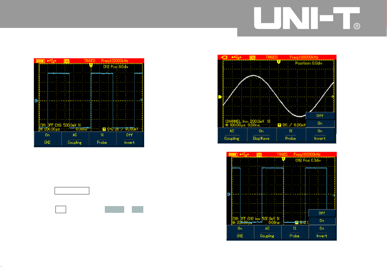
Connect UTD1000CL channel with 70mVpp A
C
sine signal mixed with 1.1V DC offset set the
channel to DC coupling, then perform AUTO
function the waveform in Figure 4 24A will
show on the screen. On the display, Positio
n
readout 53.63div indicates the channel
reference marker moves 53.63div downward from
the ho rizon tal ce ntr al line The cu rre nt
amplitude range is 20mV/div so DC offset
readout 20mV/div 53.63div =1.0726V
Vpp readout: 72mV means the AC peak to
peak value of the signal
You c an also di rec tly re ad out th e DC leve l
through AVG value
.
A
VG value: 1.0726V which stands for the
signal DC level
Through all parameters mentioned above, the
signal can be understood very easily
.
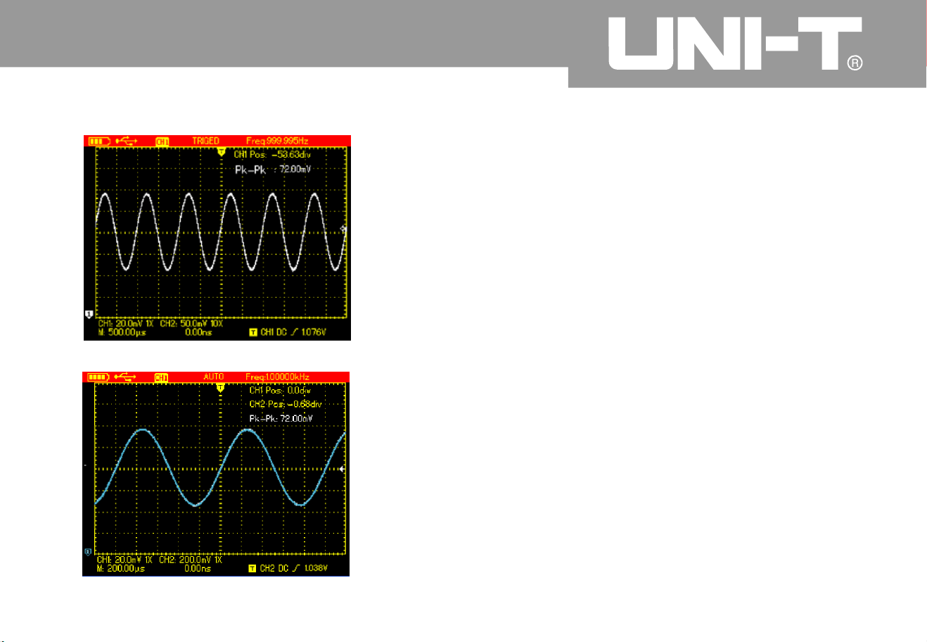
Note: For UTD1000DL models CH1 and CH
2
are both set to DC coupling when inputting the
signal above then perform the AUTO functio
n
after that also move the waveform to the center
of the display(See Figure4-24B and the
n
calculate DC offset with use of Position readout
and current amplitud e range value
h
–
UTD1000L User M anua l
A
s for traditional oscilloscope, it n eeds hard work
to complete the task, for it has to set the coupling to
A
C mode first to measur e out the AC parameters
,
and then reset the coupling to DC mode, manuall
y
adjust vertical scale and use the cursor to work out
DC parameters, see figures as below
:
Figure 4-24B UTD1000DL Setup for Signals with DC Offse t
Figure 4 A UTD1000CL Setup for Signals with DC Offse
t
2
4

UTD1000L User Manual
With the comparison shown above it is ver
y
clear that UTD1000L series is designed with a
powerful ability to measure signals at muc
h
faster speed and in a more visual way
.
Figure 4-26 DC Parameter Measurement
Figure 4 AC Parameter Measurement
25
4

Chapter 5 Using the Multimeter
About the Chapte
r
Connections to the Multimete
r
Display Indicators
This chapter introduces the multimeter functions
built in the Oscilloscope examples are also
offered to illustrate how to use the menus and the
basic measurements. To switch from Oscilloscope
mode to Multimeter mode press DMM DSO
button to access DMM mode, the display scree
n
will change into multimeter interface accordingly
.
UTD1000CL provides three multimeter input
terminals COM matched to 4-mm
banana plugs of test leads. One 10A current
divider UT-M07 is also used in the
measurements
UTD1000DL has two multimeter input terminals
COM matched to 4-mm banana plugs of
test leads One UT M0
4
4A current divider
)
and one UT-M10 mA current module are also
offe red to use in the measurements
Description:
1. Battery Indicator
2. AUTO Autoset indicator
3. Indicators for Measurement Types
:
DC Voltage Measurement
AC Voltage Measurement
DC Current Measurement
AC Current Measurement
Resistance Measurement
Diode Test
Continuity Test
Capacitance Measurement
4. Relative Measurement
5. working statusIndicator HOLD Freeze the
displa
y
6 Main Display for Measuring Values
7 Manual Ranging Indicator
V/ȍȝA/m
A
V/
ȍ
UTD1000L User M anua l

UTD1000L Us er M anual
Making Multimeter Measurements
Pre ss DSO/ D MM butt on to acces s DMM mod e
,
the display then enters into the multimeter
interface. Multimeter function s are ready to use at
the moment
.
To measure resistance do the following
:
1 Press down R button to set measurement type
to Resistance
2 Plug test lead connectors into multimeter
input terminals Black to COM and Red to
V
/
3 Connect t est leads respectively to the resistor
under test, then take resistance readings
Figure 5-1 Measuring Resistance
Measuring Resistance
ȍ

UTD1000L User M anua l
Testing Dio des Testing for Continuit
y
To test the diode do the followin
g
1 Press R button to set the measurement type to
Resistance
2 Press F1 button to select Diode option
.
3 Plug test lead connecto rs into multimeter input
terminals (Black to COM and Red to
4. Connect test leads to the tested diode the
n
forw ar d voltag e drop re adin g for the dio de
displays accompanied by the
unit V
To check the continutity do the followin
g
1 Press R to set the measurement type to
Resistance
2 Press F1 button to select Continutit
y
3 Plug test lead connectors into multimeter
input terminals (Black to COM and R ed to
4 Connect test leads to tested points The
multimeter will beep if tested resistance
between tested points is lower tha
n
Figure 5-3 Testing for Continuit
y
V/ȍ V/
ȍ
70
ȍ
measuremen
t
Fgi ure 5- 2 Test ing Di ode

UTD1000L User M anual
Measuring Capacitance
Note:
Measuring DC Voltage
˘
To measure capacitance do the followin
g
1 Press R to set the measurement type to
Resistance
2 Press F1 button to switch measurement type
to C apa ci tan ce
3 Plug test lead connectors into multimeter
input terminals (Black to COM and Red to
4. Connect test leads to the capacitor under test
,
then take the reading
.
To ensure the accuracy, please use the
relative mode if test capacitance is 5 nF
To measure DC voltage do the followin
g
1 Press down V button to set measurement type
to DC Voltage
.
2 Plug test lead connectors into multimeter
inpu t term inal s (Bla ck to COM and Re d to
3. Connect test leads respectively to tested points
,
then take DC voltage reading
.
V/
ȍ
V/
ȍ
Figure 5-5 Measuring DC Voltage
Figure 5-4 Measuring Capacitance

UTD1000L User M anua l
Measuring AC Voltage Measuring DC Current with UTD1000CL
Current
To measure AC voltage do the followin
g
1 Press V button to set measurement type to D
C
Voltage
.
2 Press F1 button to select AC Voltage option
.
3 Plug test lead connectors into multimeter
input terminals (Black to COM and Red to
4 Connect test leads respectively to tested
points, then take AC voltage reading
.
Figure 5-6 Measuring AC Voltage
To measure DC current lower than 4mA do the
followin
g
1. Press I button to set measurement type to D
C
measurement unit is you can use
F3 to toggle between mA and A ranges
the default is m
A
2. Plug test lead connectors into input terminals
(Bla ck to COM and Red to m
A
3Con
n
ect test leads to tested points the
n
take DC current reading
V/
ȍ
ȝ
A
ȝ
A
ȝ
A
Figure 5-7 Measuring DC Current lower than 4mA

UTD1000L Us er M anual
To measure DC current lower than 400mA do the
followin
g
1 Press I button to set measurement type to D
C
Current
2. Press F3 button to select mA range, and
measurement unit will be m
A
3. Plug test lead connectors into input terminals
(Black to COM and Red to m
A
4 Connect test leads to tested points then take
DC cur ren t read in
g
Figure 5-8 Measuring DC Current lower than 400m
A
To measure DC current greater than 400mA do the
foll owin
g
1 Press I b utton to se measurement type to DC
Current
2 Press F3 button to select A range, the
measurement unit will change into A accordingly
.
3 Plug10A Current divider module UT-M0
7
into input terminalsCOM and mA the
n
connect black and red test lead connectors
respectively to the module UT-M0
7
4 Connect test leads to tested points than take
the DC current reading
If test leads are connected t o COM
and without use of 10A Current divider
module UT-M07 when measuring current
greater than 400mA, the fuse in the product will be
burnt out. Please have the fuse replaced b
y
qualified personnel if the incident happens
ȝA ȝ
A
ȝA/m
A
Warnin
g

UTD1000L User M anua l
Figure 5-9 Measuring DC Current Greater Than 400m
A
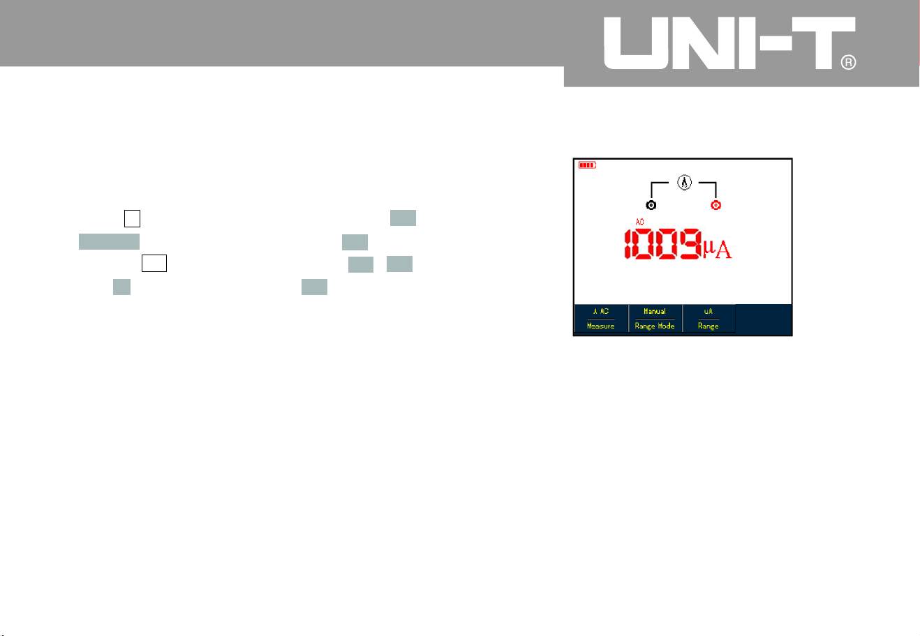
Measuring AC Current with UTD1000CL
To measuring AC current lower than 4m
A
1 Press I button to set measurement type to A
C
Current the measurement unit is You
can use F3 button to select between m
A
and A ranges the default is
2 Plug test lead connectors into input t erminals
(Black to COM and Red to m
A
3 Connect test leads to tested points the
n
take the AC current readin
g
To measure AC current lower than 400mA do the
followin
g
1 Press I button to set measurement type to A
C
Current
2. Press F3 button to select mA range, and the
measurement unit will show mA accordingl
y
3 Plug test lead connectors into input terminals
(Black to COM and Red to m
A
4C
o
nnect test leads to tested points then take
the AC current reading
ȝ
A
ȝ
A
ȝ
A
ȝ
A
ȝ
A
Figure 5-10 M easuring AC Current Lower Than 4mA

UTD1000L Us er M anual
Figure 5-11 Measuring AC Current Lower tha
n
400m
A
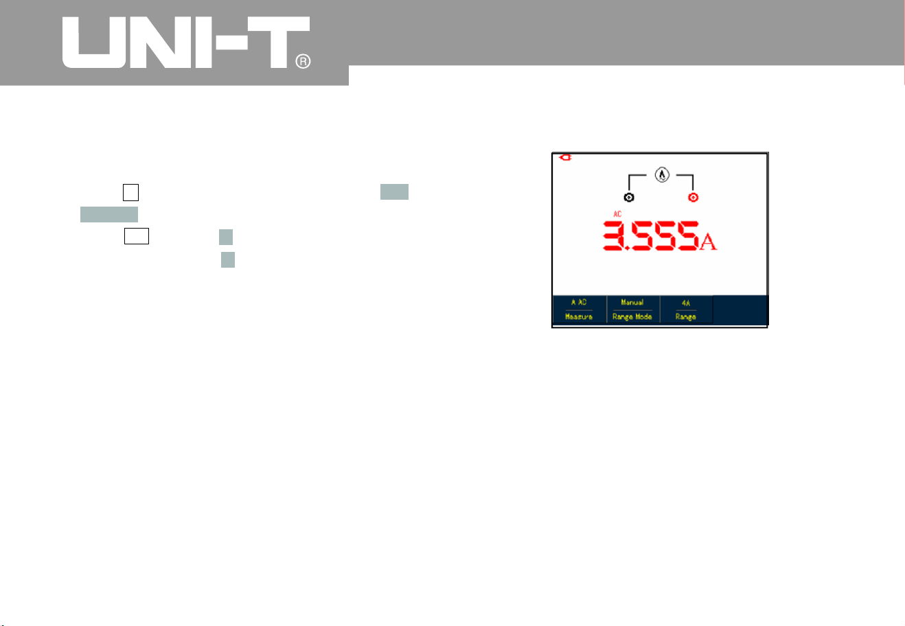
To measure AC current greater than 400mA do
the followin
g
1 Press I button to set measurement type to A
C
Current
2 Press F3 button to select A range, and the
measurement unit will change into
A
accordingl
y
3 Plug 10ACurrent divider module(UT-M07 into
Input terminalsCOM and mA the
n
insert black and red test leads properly into the
module
4 Connect test leads to tested points the
n
take the AC current readin
g
If test leads are connected to COM
and without use of 10A Current divider
module UT-M07 when measuring current
greater than 400mA, the fuse in t
h
e product will
be burnt out Please have the fuse replaced b y
qualified personnel if the incident happens
Figure 5-12 Measuring AC Current Greater tha
n
400m
A
ȝ
A
ȝA/mA
Warnin
g

UTD1000L User M anua l
Measuring DC Current with UTD1000DL
To measure DC current equal to or lower than 1m
A
do the following
:
1. Press I button to set measurement type to D
C
Current the measurement unit is you ca
n
use F3 to toggle between mA and
A
ranges the default is m
A
2. Plug mA current module (UT-M10 into input
terminals COM and then turn the switc
h
on the module to uA range
3. Insert black and red test leads correspondingl
y
into Black and Red terminals on the module
4 Then connect test leads to tested points
than take the DC current readin
g
Figure 5-13 Measuring DC Current Equal to or
Lower than 1m
A
ȝ
A
ȝ
A
V/
ȍ

UTD1000L User Manual
To measure DC current within 1mA 40mA do the
followin
g
1. Press I button to set measurement type to D
C
Current
2. Press F3 to select mA range the
measurement unit will change into m
A
accordingly
.
3. Plug mA current module (UT-M10 into input
terminalsCOM and then turn the switc
h
on the module to 40mA range
4 Insert black and red test leads correspondingl
y
into Black and Red terminals on the module
5 Then connect test leads to tested points
than take the DC current readin
g
Figure 5 -14 Measuring DC Current Lower tha
n
40mA
V/
ȍ

To measure DC current within 40mA-400mA do
the followin
g
1 Press I button to set measurement type to
DC Current
2. Press F3 to select mA range, and the
measurement unit will display mA accordingly
.
3. Plug mA current module (UT-M10 into input
terminalsCOM and then turn the switc
h
on the module to 400mA range
4 Insert Black and Red test leads correspondingl
y
into Black and Red terminals on the module
.
5 Then connect test leads to tested points
than take the DC current readin
g
Figure 5-15 Measuring DC Current within 40mA-
400m
A
V/
ȍ
UTD1000L User M anua l

UTD1000L User Manual
To measure DC current greater than 400mA do
the followin
g
1 Press I button to set measurement type to
DC Current
2. Press F3 to select A range, and the
measurement unit will display A accordingly
.
3. Plug 4A current module UT-M04 into input
terminals COM and the
n
insert test leads properly into the module
.
4. Connect test leads to tested points, then take
DC current read ing
.
If test leads are directly connected to
V/ and COM terminals without use of 4A current
module UT-M04 when measuring the current
greater than 4 00mA the fuse in the product will
be burnt out Please have the fuse replaced b
y
qualified personnel if the incident happens
Figure5-16 Measuring DC Current Greater tha
n
400m
A
V/
ȍ
ȍ
Warnin
g
UTD1000L User M anua l
Measuring AC Current with UTD1000DL
To measure AC current equal to or lower tha
n
1mA do the followin
g
1 Press I button to set measurement type to A
C
Current the measurement unit is You
can use F3 button to select between m
A
and A ranges the default is
2 Plug mA current module (UT-M10 properl
y
into input terminals COM and then tur
n
theswitchonthemoduletouArange
3 Insert Black and Red test leads correspondingl
y
into Black and Red terminals on the module
.
4. Connect test leads to tested points, then take the
A
C current reading
.
Figure 5-17 Measuring AC Current Equal to or
Lower than 1m
A
ȝ
A
ȝ
A
ȝ
A
V/
ȍ

UTD1000L User M anua l
To measure AC Current within 1mA-40mA do the
followin
g
1 Press I button to set measurement type to A
C
Current
2. Press F3 to select mA range, the
measurement unit will change into m
A
accordingly
.
2 Plug mA current module UT-M10 proper l
y
into input terminals COM and then tur
n
theswitchonthemoduleto40m
A
range Insert Black and Red test leads
correspondingly into Black and Red terminals
on the module
4. Connect test leads to tested points, then take the
A
C current readin
g
Figure 5-18 Measuring AC Current Lower tha
n
40mA
V/
ȍ

UTD1000L User M anua l
To measure AC Current within40mA-400mA do
the followin
g
1 Press I button to set measurement type to A
C
Current
2. Press F3 to select mA range, the
measurement unit will change into m
A
accordingly
.
3. Plug mA current module (UT-M10 properly into
input terminals COM and then turn the
switch on the module to 4 00mA range
4. Insert Black and Red test leads correspondingl
y
into Black and Red terminals on the module
.
5. Connect test leads to tested points, then take the
A
C current reading
.
Figure 5 19 Measuring AC Current within40mA-
400m
A
V/
ȍ
UTD1000L Us er M anual
To measure AC Current greater than 400mA do
the followin
g
1 Press I button to set measurement type to A
C
Current
2. Press F3 to select A range, the measurement
unit will change into A accordingly
.
3. Plug 4A current divider module (UT-M04
properly into input terminals COM and
then insert Black and Red test leads
correspondingly into the module
5. Connect test leads to tested points, then take the
A
C current reading
.
If test leads are connected to V/
and COM terminals without use of 4A current
module UT-M04 when measuring the current
greater than 400mA the fuse in the product w ill
be burnt out. Please have the fuse replaced b
y
qualified personnel if the incident happens
.
Figure 5-20 Measuring AC Current Greater tha
n
400m
A
V/
ȍ
ȍWarnin
g

UTD1000L User M anua l
Data Hold Making Rela tive Meas urement
You can freeze the displayed readings any time as
you want
.
1 Press RUN /STOP to freeze measuring values
and HOLD icon blinks on the displa
y
2 Repress RUN /STOP to restore the
measurement
.
Figure 5-21 Freezing Measurement Values
Relative measurement displays a current
measuring result relative to the specific reference
value.
Refer to capacitance measurement in relative
mode. First of all you need to obtain a reference
value:
1. Press button to set measurement type to
Resistance
2 Press F1 button to select C apacitance optio
n
3. Connect test leads to input terminals (Black to
COM and Re d t o V/
4. Wait until the reading becomes stable, the
n
press F2 button to access the relative mode
,
icon shows on the upper display and the
reference value appears just below icon
.
5. Connect test leads to the capacitor under test
,
then take capacitance reading on the display
Ƹ
Ƹ
R
ȍ

UTD1000L User M anua l
Figure 5-22 Measuring Capacitanc in Relative
Mode
The multimeter defaults at auto mode. To access
manual ranging, operate as follows
:
1. Press V or R button, and measure mode
option is AUTO
2 Press F 2 to select manual measure mode
then the ranging mode will change into Manual
status accordingl
y
3.Under m anual ranging mode, keep pressing F
3
button to reach up to the highest range
after th at, the n the se lect ed rang e jum ps dir ect l
y
to the lowest range and circulates again
.
The currently selected range shows just above
measurin g readings.
4 Press F2 button, Auto icon shows on left upper
display i
n
dicating the multimeter has
returned to full autoset mode
Figure 5 -23 Manual Rangin
g
Selecting Manual Auto Rangin
g

UTD1000L User M anua l
Chapter 6 Using the Osc illoscope
in Detail
s
About the Chapte
r
Setting Vertical Syste
m
This chapter offers a st ep-by-step introductio
n
on UTD1000L Series functions Detail
information about functional buttons on the front
panel and operation examples are included
here It is recommended that you should read
through this chapeter in order to get more and
systematic knowledge of the Oscilloscope
.
The channel is designed with independent setup
menu, press CHANNEL button to display the
operating menu shown as below
:
Figure 6 1A Channel Setup Menu
UTD1000CL Channel Setup

UTD1000L Us er M anual
See Channel Menu in Following Table
:
Tabl e 6 1
A
Couplin
g
Wave
Displ a
y
Probe
Factor
Invert
D
C
AC
Groun
d
O
n
Off
1
1
0
10
0
100
0
h
h
h
h
Off
O
n
A
C&DC components pass
DC component is blocke
d
Display DC level when the channel input terminal is equivalently grounded
.
To display the channel waveform
To turn off the channel waveform displa
y
Select one of them to match to the probe to ensure accurate reading
.
Four types are available:1 10 100 1000
hǃ hǃ hǃ h
To display the waveform normally
.
To invert the waveform displa
y

UTD1000L User M anua l
Moving Waveform Verticall
y
Note:
Setting wa veform di spla
y
When UTD1000CL channel marker turns solid
press Up and Down arrow buttons to move the
waveform verticall
y
Figure 6 2A Moving Waveform Verticall
y
if the channel marker is internally empt
y
press SELECT button to access the solid status
before moving the waveform vertically
.
Open the channel menu, and then press F
2
button to turn on/off waveform displa
y
Figure 6 3A Turn off Waveform Displa
y

UTD1000L Us er M anual
Set Probe Factor UTD1000DL Channel Setup
To match with the probe factor on the probe
,
you need to set up corresponding factor in channel
menu. For example, the probe factor is 10:1
please set Probe option in the menu to 10
Do the same setting for other selected probe
factor in order to ensure accurate voltage
readin
g
Under channel menu, press F3 under channel
menu to set up probe factor
Probe Attenuation Factor VS Menu Option, see
following table
:
Tabl e 6 2
A
The channels have their own setup menus.
Repeat pressing CHANNEL to toggle betwee
n
CH1 and CH2 menus and display correspondin
g
menu options as shown below
:
Figure 6-1B Channel Menu Setup
h
Probe Atte nuatio
n
Facto
r
1:1
10:1
100:1
1000:1
Menu Optio
n
1h
1 h0
10
0
h
100
0
h

UTD1000L User M anua l
Please see channel menu in the following table
:
Tabl e 6-1 B
Channel
Couplin
g
Probe
Factor
Invert
Off
O
n
D
C
AC
GND
1
1
0
10
0
100
0
h
h
h
h
Off
O
n
Turn off CH1 or CH2 waveform
Turn on CH1 or CH2 w aveform
A
C&DC components pass
DC component is blocke
d
Display DC level when the channel input terminal is equivalently grounded
Select one of them to match to the probe, to ensure accurate reading
.
Four types are available: 1 10 100 100
0
hǃ hǃ hǃ h
To display the waveform normally
.
To invert the waveform displa
y

UTD1000L User M anua l
1.Moving Waveform Vertically Setting Waveform Displa
y
Use Up and Down buttons to move the current
waveform vertically when the channel marker
becomes solid. If you want to move the waveform
from another channel, please press CHANNEL
button again before moving the waveform
.
Figure 6-2B Moving Waveform Verticall
y
Press CHANNEL button to toggle betwee
n
different channels. In the channel menu p ress
F1 submenu button to turn on/off the waveform of
the current channel. In order to on/off another
channel waveform, you need to press CHANNEL
button again before pressing F1 butto
n
Figure 6-3B Turn on Waveform Display for Dual
Channels

UTD1000L Us er M anual
Setting Probe Fac to
r
Changing Timebase
Moving Waveforms Horizontall
y
h
To match with the probe factor on the probe
,
you need to set up corresponding factor in channel
menu. For example, the probe factor is 10:1
please set Probe option in the menu to 10
Do the same setting for other selected probe
factor in order to ensure accurate voltage
readin
g
Under channel menu, press F3 to set up
probe factor To set up probe factor for another
channel please press CHANNEL again a nd the
n
theF3button
.
Probe Attenuation Factor VS Menu Option, see
following table
:
Tabl e 6-2 B
Press s/ns button slow down or speed up the
sca n rate fr om 10n s o r 5ns/d iv 50s/ di
v
Notes: For 25MHz bandwidth models 10ns/di
v
50s/div 50MHz bandwidth Models 5ns/di
v
50s/di
v
Press Left and Right buttons to adjust pretrigger
depth. The trigger location is usually set at
horizontal center on the screen. With the
adjustment you can observe div pretrigger
and delay data Through moving the waveform
horizontally, more trigger information can be
viewed, which let users know more about
pretrigger situation. For instance, by observing and
analyzing pretrigger data of glitches occurring i
n
circuit start up you can trace down the cause
to the glitches
Setting Horizontal Syste
m
Probe Atte nuatio
n
Facto
r
1:1
10:1
100:1
1000:1
Menu Optio
n
1h
1 h0
10
0
h
100
0
h

UTD1000L Us er M anual
PressHORIZONTALbuttontoswitcho
n
horizontal menu refer to the following figure
Figure 6-4 Horizontal Setup Men
u
There are two options in horizontal menu: Window
and Hold-Off
Switch on horizontal menu and press F1 button
to zoom in one segment of the wavefom. The
timebase for expanded window shouldn t be lower
than that of main window. Note: Timebase faster
than 100ns cannot enter into expanded window
Figure 6-5 Screen Display under Window
Zoom
Zooming in out Wa veforms

UTD1000L User M anua l
Under window zoom function there are two
separate display zones as indicated in the figure
above The upper part is for the original waveform
.
Press OK button and then use Left and Right
buttons to select the waveform to be expanded o
n
the left or right, or enlarge or narrow down the
selected zone with s/ns butto
n
The lower display is for the expanded
waveform corresponding to the selected original
zone. One point worth mentioning is that compared
with the main timebase, the expanded timebase
has improved the resolution for the waveform
display ( See Figure 6-5). Since the displayed
waveform corresponds to the selected zone of
upper part, using s ns button to narrow down the
selected zone can enable the expanded waveform
to have better timebase namely a higher
waveform amplification factor in a horizontal
directio
n
Switch on horizontal menu, use Right and Left
buttons to adjust hold-off time (100ns-1.5s It ca
n
be applied to observe complex waveforms eg
:
bur st Hold-off tim e is to adju st dat a acqui siti o
n
period of the oscilloscope to stay in a integral
multiple related to the period of complex
waveform so that the Oscilloscope and complex
waveform can synchronize
.
For example, apply tested combined signals into
Ch1 Press HORIZONTAL to turn on horizontal
menu then press Right and Left buttons to adjust
the hold-Off time until displayed waveform
become stable See Figure 6-
6
Adju sti ng Trigger Hold Of
f

UTD1000L Us er M anual
Figure 6-6 Trigger Hold Off
1. The trigger hold-off time can be adjusted onl
y
when horizontal menu displays
.
2. Generally hold-off time is a little smaller tha
n
Big Period for instance for RS23
2
communication signal waveform hold off
time sh oul d b e a li ttl e large r t han st art edg e
time of each frame in order to easily observe
the waveform
Trigger system determines when the
Oscilloscope starts to acquire data and displa
y
waveforms. O nce the trigger is properly set, the
Oscilloscope can transform unstable signal into
meaningful waveform. When the acquisition starts
the Oscilloscope contin
uously acquires enoug
h
data to fill the pretrigger portion that is
displayed to the left of trigger point Then the
trigger occurs, the Oscilloscope will continue to
acquire enough data to fill the posttrigger
waveform to the right of trigger point. TRIGGE
R
button is designed to set up the Oscilloscope
trigger functions
TRIGGER Trigger menu butto
n
Trigger Level: to set up signal voltage that
corresponds to the trigger point
Press TRIGGER button to turn on trigger menu as
indicated in the figure below, then press F1 butto
n
to switch between different trigger types
.
Press F2 to select trigger source
.
Ā
Note:
Setting Trigger Syste
m

UTD1000L User M anua l
Figure 6-7 Trigger Men
u
Four trigger types are available: edge, video, pulse
width a nd slop e, ev ery of whic h is c oup le d w it
h
different functional menu There is still one
type common setting used to set up trigger
source, t rigger coupling and trigger modes
.
Trigger on rising or falling edge
.
You can adjust trigger level to change vertical
location on the edge for trigger point that is
the cross point between trigger level line and
the signal edge on the screen
.
Trigger when the pulse
width of trigger signal reaches up t o preset trigger
conditions
.
Trigger on fields or lines of
standard video si
g
nal
Use the rise or fall speed r ate
of the signal as trigger conditio
n
Ch eck det ail s for diffe ren t kin ds of tri gger m enu s
Trigger Control
s
Edge Trigger:
Pulse Width Trigger:
Video Trigger:
Slope Trigger:
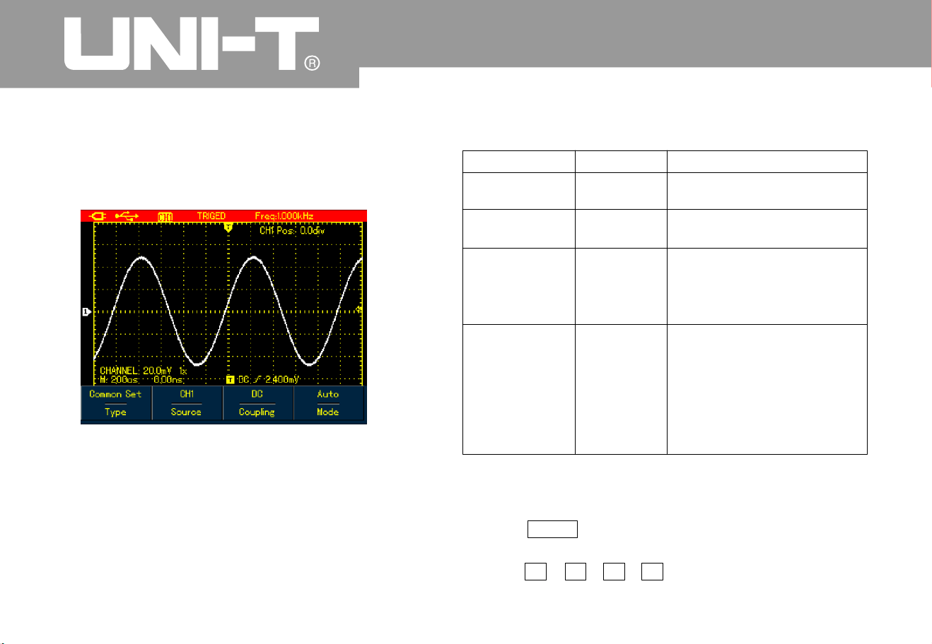
UTD1000L User M anua l
Comm on S ettin
g
Common Setting is used to set up common trigger
items, refer to the table below for details
:
Figure 6-8 Trigger -- Commo
n
UTD1000L Us er M anual
Menu
Type
Source
Couplin
g
Mode
Setting
s
Commo
n
CH1
CH
2
AC
D
C
HF Reject
A
ut
o
Normal
Descriptio
n
to set up commo
n
trigger items
Set CH1 s trigger source
Set CH
2
a
as trigger source
DC component is blocked
DC &AC components pass
Rejec t hig h f req ue nc
y
component 80kH
z
˚a
t
The Oscilloscope
automatically acquires data
when no trigger signal has
been detected
.
A
cquire waveform onl
y
when the trigger conditio
n
is met
Table 6-
3
Note:
To set up the common setting, shortcuts are also available
to execute the operation
:
1. Press SHIFT button, Shift icon displays on right upper
corner of the scree
n
2. Press F1 F2 F3 F4 button to display commo
n
setting men
u

UTD1000L Use r Manual
Edge Trigge
r
Edge trigger is to trigger on trigger threshold
value of signal edge. Please see the table
below for edge trigger men
u
Figure 6-9 Trigger Edge Type
Tab l e 6
4
Menu
Type
Slope
Setting
s
Edge
Rise
Fall
Descriptio
n
Set trigger Type to Edge
.
Set to trigger on rise edge
of signal
.
Set to trig g er on fall edg e
of signal
.

UTD1000L User Manual
Pulse Width Trigge
r
It determines the trigger time based on pulse width
,
which helps you to capture abnormal pulse b
y
setting specific pulse width conditions
.
Figure 6-10 Trigger Pulse Wdith Type
Table 6 5
Menu
Type
Polarit
y
Qualifier
Time
Setting
s
Pulse
Widt
h
Positive
Negative
ζ
η
Descriptio
n
Set trigger Type to Pulse
Widt
h
Set positive pulse w idth as
trigger signal
Set negative pulse width as
trigger signal
Trigger when input pulse width
equals to set value
Trigger when input pulse width
is less than set value
Trigger when input pulse width
is greater than set value
To se t up pulse widt
h
time
value use Left and Righ
t
arrow buttons to set the
value when the menu is
displayed

UTD1000L User M anua l
Video Tri gge
r
Trigger on fields or lines of NTSC or PAL
standard signals if video trigger is selected
Figure 6-11 Trigger Video Type
Table 6 6
Menu
Type
Format
Syn
Setting
s
Vid e
o
PA
L
NTS
C
A
ll Lines
Odd Fiel
d
Even Fiel
d
Descriptio
n
Set trigger Type t o Video
Trigger on P A
L
Trigger on NTSC format
form a
t
video signal
video signal
Trigger synchronically on all
lines
.
Trigge r on odd fie lds
.
Trigger on even fields

UTD1000L Use r Manual
Slope Trigge
r
Trigger occurs only after rise or fall speed rate
meets set value
.
Figure 6-12 Trigger Slope Type (Page 1
)
Figure 6-13 Trigger Slope Type Page
2
–

Table 6-
7
UTD1000L User M anua l
Menu
Type
Slope Type
Qualifier
Next
Slew Rate
Threshol
d
Back
Setting
s
Slope
ζ
Rise
Fall
Descriptio
n
Set trigger Type to Slope
Tr ig ger on ris ing edg e that tra vers e bet ween thr esho ld s
Trigger on falling edge between thresholds
Trigg er When t he slo pe is gre at er than the se t v al ue of s le w r at e
.
Trigg er When the sl o p e is less tha
n
Trigger When the slope equals to the set value of slew rate
.
thesetvalueofslewrate
Page 2 of Sl ope Me n
u
To set up slew rate value, use Left and Right arrow buttons to
pulse width time when the menu is displayed
.
Use Up a nd Do wn buttons to move l ow-le vel thresho l d
Use Up a n d Do wn buttons to mov e H igh- lev e l t hre sh ol d
Use Up a n d Do wn butto ns to move l o w- an d h ig h-l e ve l thresho ld s
.
To r eturn to Page 1 of Slope Menu
.
Low
Hig
h
Low&Hig
h
η

UTD1000L Us er M anual
Term Explanatio
n
Input Channel :
Trig ger Mode:
Auto:
Norm al
Single:
Trigger Couplin
g
DC:
HF Reject:
1 Trigger Source Input channel is used as the
trigger source
Input channel (CHI) is the most
commonly used trigger source. For the channel
selected as the trigger source, it should be
swit che d on bef ore it wor ks nor ma lly
.
2 decide what the oscilloscope will
do when no trigger event occurs. Three trigger
modes are offered : Auto, Normal and Single
The system automatically acquires data
even there is no signal input and therefore displays
scan reference line on the screen when the
trigger occurs it converted into trigger scannin
g
and synchronizes with the signal on it s ow
n
Note: The O scilloscope will go into SCAN mode if
waveform scan rate is set at 50ms/div or lower
timebase
Under this mode, the Oscilloscope
acquires the waveform only after the trigger
conditions are met. It stops to acquire and keeps
waiting if no signal is input O nce the trigger
occurs, the scan starts
.
YoujustneedtopressRUNbuttonif
under single mode then t he Oscilloscope waits
to trigger. It begins to acquire and display all
acquired waveforms once single-shot trigger signal
is detected, after that, it stops
.
3 Todecidetopasswhic
h
kind of components through the trigger circuits
The types include: DC, AC a
n
d Hf Reject
.
passes through all components of the
signal
A
C blocks DC component and attenuate
signals at 10H
z
attenuates high frequenc
y
component at 80kHz
˘
˚
Ŷ
Ŷ
Ŷ
Ŷ
Ŷ
Ŷ
Ŷ

UTD1000L User M anua l
4 Pretrigger/Delay Trigge
r
Note:
Capture data before
/after the trigger event The trigger is usuall
y
located at the horizontal center point on the screen
,
for example, you can observe 6div pretriger and
delay information adjusting the waveform
horizontally can let you view on more pretrigger
information Pretrigger can indicate what the
waveform is like before the trigger event. So this
function can make it easy, for instance to find
out the cause of glitche s in start moment of
circuits through observing and analyzin
g
pretrigger data
Pres s A CQ UIRE bu tton to ac cess ac quis itio
n
mode see the following table
Table 6-
8
1Useno
rmal mode when you observe single
shot si gnal
2. Please select Peak mode if you want to
observe signal envelope and also to avoid any
mix-up
Setting Acquisition Mode
Menu
Mode
AVG Number
Setting
s
Normal
Peak Detect
A
VG
225
6
a
Descriptio
n
Set to normal samplin
g
SettoPeakDetectmode
,
Set to AVG sampling mode
To se t AVG ti mes
,
stepping in multiples of
two, t ha t is from 2 4
8
16 32 64 128 256 to
512 tur nL ef t a nd Ri g ht
arrow b uttons to chan ge
averag e times i
n
displayed men
u
only displaye
d
under AVG
mode

UTD1000L Us er M anual
Term Explanatio
n
Normal Mode:
Peak Detect:
AV G Mode:
Fast Acquisition:
ˈ
The Oscilloscope samples the
signals at equal time interval to create the
waveform on the display
.
Under this mode, the Oscilloscope
uses Max. and Min. values detected in each samplin
g
interval to form waveform on the display It is
suitable to capture and display narrow pulse whic
h
may probably be neglected if using Normal mode
However the noise under Peak Detect sounds
louder
The Oscilloscope captures certai
n
numbers of waveforms and calculates their average
values that will be used to form waveforms o
n
the display This mode can reduce random noise
it only acquires points for Mi
n
memory depth required for display which ca
n
shorten the hold off time between eac
h
acquisition and realize superb capture rate It ca
n
significantly increase the possibility to find out rarel
y
seen issue
.
Press DISPLAY button to access display menu,
please refer to the follow table
:
Figure 6-14 Waveform Display Setup
Setting the Display

UTD1000L User M anua l
Table 6-
9
Format
Format
Graticule
Persist
YT
X
Y
Vector
Dots
Full
Gri
d
Cross H air
Off
1s
3s
5s
Infinite
To display relationship between voltage(vertical) and time(Horizontal)
.
X-Y display mode using Ch signal to form X axis and Ch2 signal for
Y
axis applicable only for dual channel model
1
Connect
Directly display sample dots
sample dots and displa
y
To set the graticule of waveform display zone to Full, Grid and Cross
Hair mode
Update the waveforms at normal rate
Update after wavef orm data is hold for 1 second
Update after wavef orm data is hold for 3 seconds
Update after wavef orm data is hold for 5 seconds
,
Waveform data is kept on the screen, new data uld
lay continuously
.
if any co be added
into the disp
Menu
Setting
s
Descriptio
n

UTD1000L User Manual
Te rm Explanation:
Displa y F ormat:
Update Rate:
Slow Scan Mode:
VECTOR Display fills out all
blanks between neighboring points DOT
Display just shows sample points
The times that the oscilloscope
updates the waveforms per second. it reflect how
fast the Oscilloscope could allow you to observe
signal dynamic change
.
Y-T Mode In this mode Y axis represents
voltage and X axis for the time
When th e timeb as e is set a t
50ms/div or lower the Oscilloscope will enter
into sl ow scan m ode T his mod e is ap plie d to
observe low frequency signal It is
recommended that channel coupling is set to
D
C
The sec ti on bel ow int rodu ce s i n det ail s the
powerful auto measurement function owned b
y
the Oscilloscope Press MEASURE button to
open auto measurement menu, see the table
below
Figure 6 15A UTD1000CL Auto Measurement
Menu
Setting Auto Measurements

Figure 6-15B UTD1000DL Auto Measurement
Men
u
Table 6-10
UTD1000L User M anua l
Source
A
ll
Select
Clear
CH1
CH
2
O
N
OFF
O
N
OFF
Select CH1 as the signal
source
.
Select CH2 as the signal
source
.
To measure all parameter s
.
Turn on auto measurement
function
.
To select the parameters to be
measured by using SELECT
button.The selected parameter
will be displayed on the
screen. Max.4 items can be
choosen at
Turn off customized parameter
selection box
atime
Menu
Setting
s
Descriptio
n
To clear the displayed
customized parameter
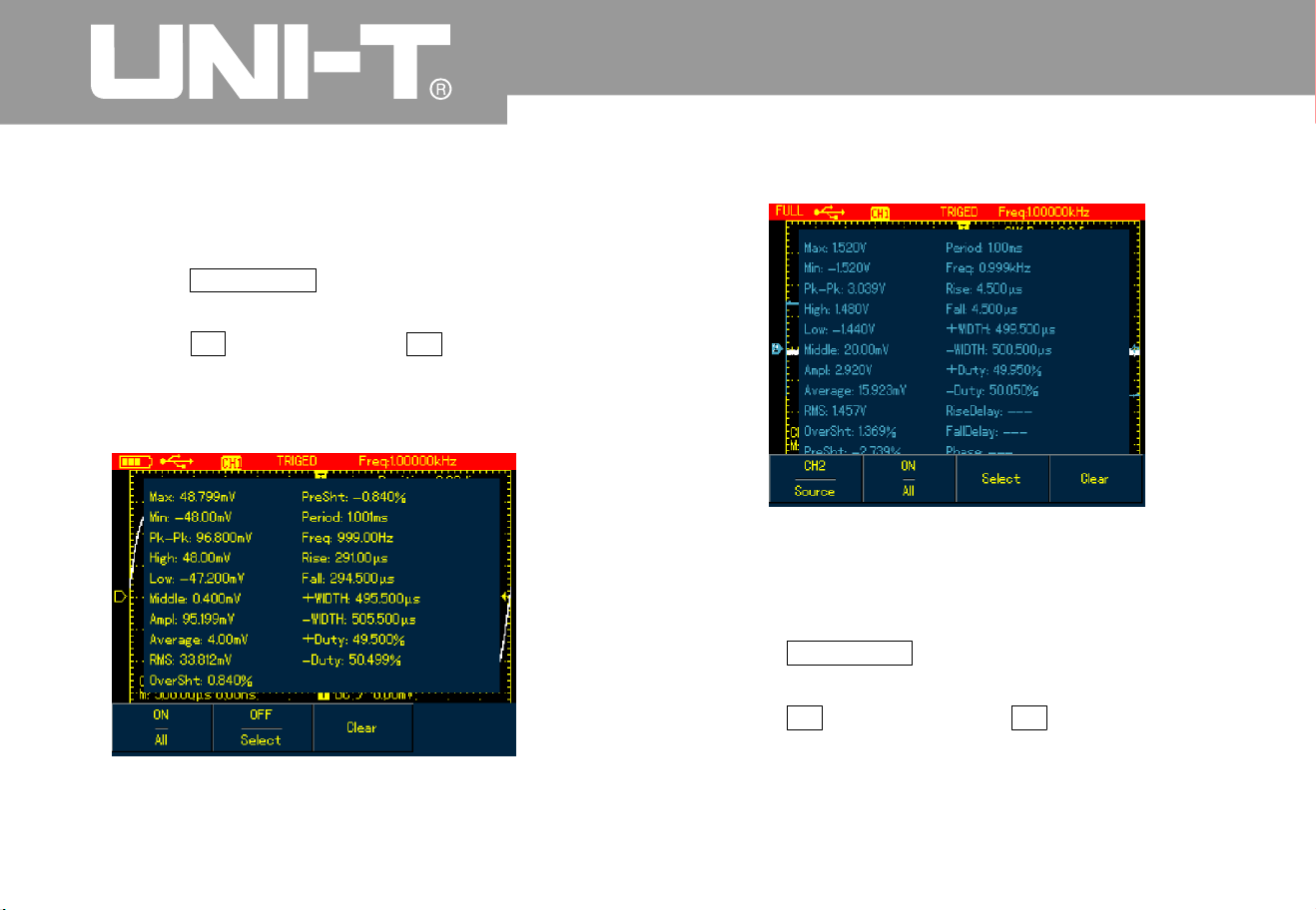
Case 1 To display all measurement parameters
of the displayed channel, do the followin
g
1 Press MEASURE button to open parameter
measurement men
u
2 Press F1 of UTD1000CL F2 of UTD1000DL
to set All option to O
n
Then all measurement parameters display on the
screen. See the Figures below
:
Figure 6 16A UTD1000CL measures all
parameters
Figure 6-16B UTD1000DL measures all
parameters
Case 2 To measure Vpp and Amplitude
parameters do the followin
g
1 Press MEASURE to open parameter
measurement men
u
2 Press F2 of UTD1000CL F2 ofUTD1000DL
button to open parameter selection box
3 Press Arrow Buttons t
o select Vpp parameter
UTD1000L User Manual
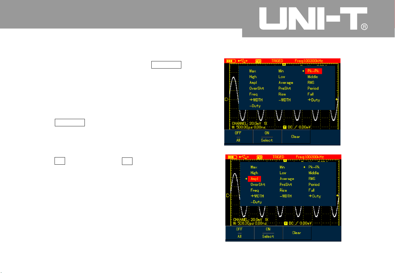
4 With Vpp parameter chosen press SELECT
to confirm and one marker will appear o
n
the front of Vpp parameter to indicate it has
been successfully selected the parameter
will show on the display accordingl
y
5 Do the same to select Amplitude parameter
6 Press SELECT to confirm one marker also
show on the front of Amplitude parameter
and then the parameter displays on the
scree
n
7 P res s F2 of UTD1 000C L F 3 of UTD100 0DL
to turn off parameter selection box
See the following figures for Vpp and Amplitude
parameters displayed on the upper right part of
screen
:
UTD1000L User M anua l
Figure 6-17 Select Vpp Parameter
Figure 6-18 Select Amplitude Parameter

Figure 6-19 Display Selected Parameters
Parameter selection is to measure
parameter immediately. There are 19 types of
parameter measurements for UTD1000CL and 2
2
types available in UTD1000DL Under general
circumstances not all parameters but just
some of them are required to be measured
.
Therefore the users can customize their
measurements as expected. The software ca
n
select up to 4 p aramet ers displayed on the screen
.
A
uto Parameter Measurements
Figure 6 -20 Voltage Measurement
The voltage parameters that the Oscilloscope ca
n
automatically measure include
:
Voltage measured
from the highest point of waveform to the zero
groun
d
Voltage m easured f rom
the lowest point to the ground
Voltage measured from the flat
top to the ground
.
Note
Maximum Value (Vmax
Minimum Value Vmi
n
To p Value (Vtop
UTD1000L User Manual

Base Value (Vbase
Middle Va lue (Vmid)
Peak-to-Peak Value (Vpp
Amplitud e (Vamp
Overshoot:
Preshoot
Average Value
RMS Value (Vrm
s
Voltage m easured f rom the
base of the w aveform to the ground
a half of amplitude value
Voltage measured
from the hi ghe st poin t t o the low est po int of
wavefo rm
Votage measured from the
top to the base of the waveform
Maxi Top Amplitudex100%
Min-Low)/Amplitudex100%
The arithmetic mean over one
cycle in the waveform
Effective value, the r oot mea
n
square voltage over one cycle in AC signal
waveform that corresponds toDC voltage w it
h
equal generated energy calculate d in this cycle
.
Figure 6-21 Time Measurement
UTD1000L User M anua l

The time parameters the Oscilloscope ca
n
automatically measure contain
:
Thetimerequiredtorisefrom10%
to 90% of waveform amplitude
The time required to fall from 90% to
10% of waveform amplitude
The distance between the mid 50% amplitude
points of a positive pulse
Negative Pulse Width ( Widt
h
The distance between the mid (50%) amplitude
points of a negative pulse
The delay time between risin
g
edges from A to B
The delay time between fallin
g
edges from A to B
the rati o of
positive pulse width to the period
the ratio of
negative pulse width to the period
Press RECORD button to open waveform
record menu There are two independent menus
shown as below
Figure 6-22 Waveform Record Menu
RiseTime
FallTime
Positive Pulse Width ( Width
Rising De lay:
Falling Delay:
Positive Duty Cycle ( Du t
y
Negati ve Duty Cycle ( Dut
y
Recording
Recording and Storage
UTD1000L User Manual

Set u p as the followi ng table:
Note:
Table 6-11 Record Men
u
Table 6-12 Save Menu for Recorded Waveforms
You can also save the recorded waveform to
PC using the control sofeware and play it on PC
.
Case 1 To record channel waveforms and save
them to the internal memory, do the following
:
1 Press RECORD button to access record menu
2 Press F1 to set to Record optio
n
3 Press F4 to begin recording. To stop
recording, press F3 butto
n
UTD1000L User M anua l
Wave Recor
d
Pla
y
Stop
Recor
d
Recor
d
To turn on/off waveform
record function
.
T
o
play recorded
wav efor m
To stop recording or
playing w aveforms
To begin the recording
.
Menu
Setting
s
Descriptio
n
Figure 6-23 Save Menu for Recorded Waveforms
Wave Recor
d
Save
Recall
Thereare1-5locatio
n
option s avail ab l e, use
arrow buttons to select
when th e m en u d isp l ays
To save recorded
wave form to in ter na l
memory
.
To r ecall the waveform
record that is saved i
n
internal memor
y
Menu
Setting
s
Descriptio
n
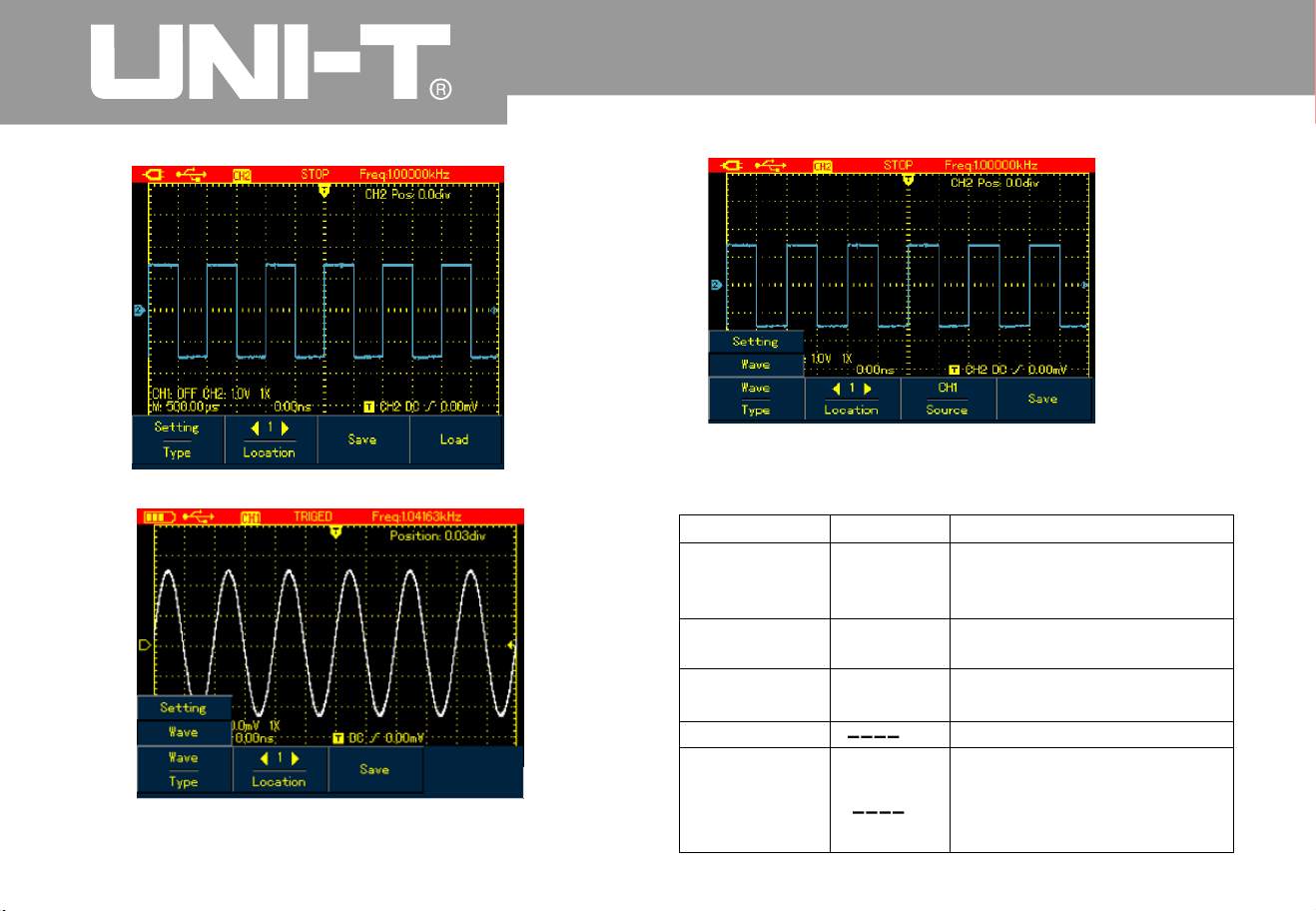
Set up the storage menu as follows
:
Table 6-13
UTD1000L User Manual
Figure 6-26 UTD1000CL Waveform Storage Menu
Figure 6-26B UTD1000DL W aveform Storage Menu
Type
Location
Source
Save
Recall(refer t
o
the following
section for
recall setup
)
Setup
Waveforms
1-2
0
To save current setups of
menus
To save channel waveforms
Use arrow buttons to select
storage location
.
To select the channel of the
saved waveform
.
To save the selected items
To r ecall t h e s a v ed
parameters when the
menu is on
.
Menu
Setting
s
Descriptio
n
CH1
CH
2
Figure 6-25 Setting Waveform Storage Menu

4 Press F1 to set to Save optio
n
5 Use Arrow Buttons to set the location to 1
6 Press F3 to save the recorded waveform
,
Saving shows on the screen Whe
n
Saving icon disappears it indicates the
waveforms have already been saved into internal
memory
.
Model UTD1000CL can record up to 30
0
screens of waveforms and it is up to 150 for Model
UTD1000DL If following operations are performed
during recording the recording will stop
Pre ss RUNS TOP/SIN GL E butto
n
Ŷ Press AUTO or SHIFT+AUTO butto
n
Ŷ Turn Timebase range to access SCAN mode
.
Case 2: To recall recorded waveform in C ase
from the internal memory and replay it do the
followin
g
1 Press RECORD to access record menu
2 Press F1 to set to Save optio
n
3 Press Arrow Buttons to set Location to 1
4 Press F4 to begin r ecalling, loadin
g
indicates o n the screen after the loadin
g
finishes Load Success indicates
5 Press F1 to set to Record optio
n
6 Press F2 button to begin playing the recalled
waveforms a utomatically, press F3 to stop or use
Arrow Buttons to select the waveform to be played.
Figure 6-24 Replay Waveform Record
To store the waveforms, do the following
:
1. Press SHIFT button, and shift icon shows o
n
upper right part of scree
n
2. Press STORAGE button to acc ess storage
men
u
ĀĂā
ĀĂā
ĀĂā
Ā ā
Note
Storage
Ŷ
UTD1000L User M anua l

Recalling
To recall the waveforms, press S HIFT button and shif
t
icon shows on the upper right part of screen then press
REF to access waveform recall menu
Figure 6-27 Recall Reference Waveforms
Set up as shown in the following table
:
Table 6-14
UTD1000L User Manual
Ref Wave
Locatio
n
Recall
Clear
REF
A
REF B
1-20
Model UTD1000CL default at
REFA optio
n
UTD1000DL can recall REF
A
or REFB individually or both
of them at the same time
Use Right and Left buttons to
select the locatio n to be
recalled
.
To begin the recallin
g
For Model UTD1000CL it s
used to turn off recalled
waveform
For Model UTD1000DL it s
used to turn off current
waveform( REFA or REFB
Tabl e 6-1 4
Menu
Setting
s
Descriptio
n

Case 1 To save and recall channel waveforms
to the internal channel
:
1. Press SHIFT and shift icon shows on upper
right part of scree
n
2. Press STORAGE to access storage menu
3. Press F1 to set Type to Waveform
4. Press Left&Rightbuttons to set Location to 1
press F3 to select target Source Onl
y
available in UTD1000D
L
5. Press F3 of UTD1000CL to save and also
F3 button for UTD1000DL then storage
success shows on the display , indicat ing the
waveform has been successfully saved into the
Oscilloscope
6.Press SHIFT shift icon shows on upper r ight
part of display
.
7.Press REF to access waveform recall men
u
8.Press F1 of UTD1000DL to select betwee
n
REFA or REFB UTD1000CL defaults at
REFA
9.Press Left &Right arrow buttons to set
Location to 1
10 Press F3 to recall, Load Success will
show to indicate the waveform has bee
n
successfully displayed on the screen too
11 Press F4 to turn off the current reference
waveform
.
Ā
ā
Āā
Saving Waveform
s
Re call ing Wa vef orm
UTD1000L User M anua l
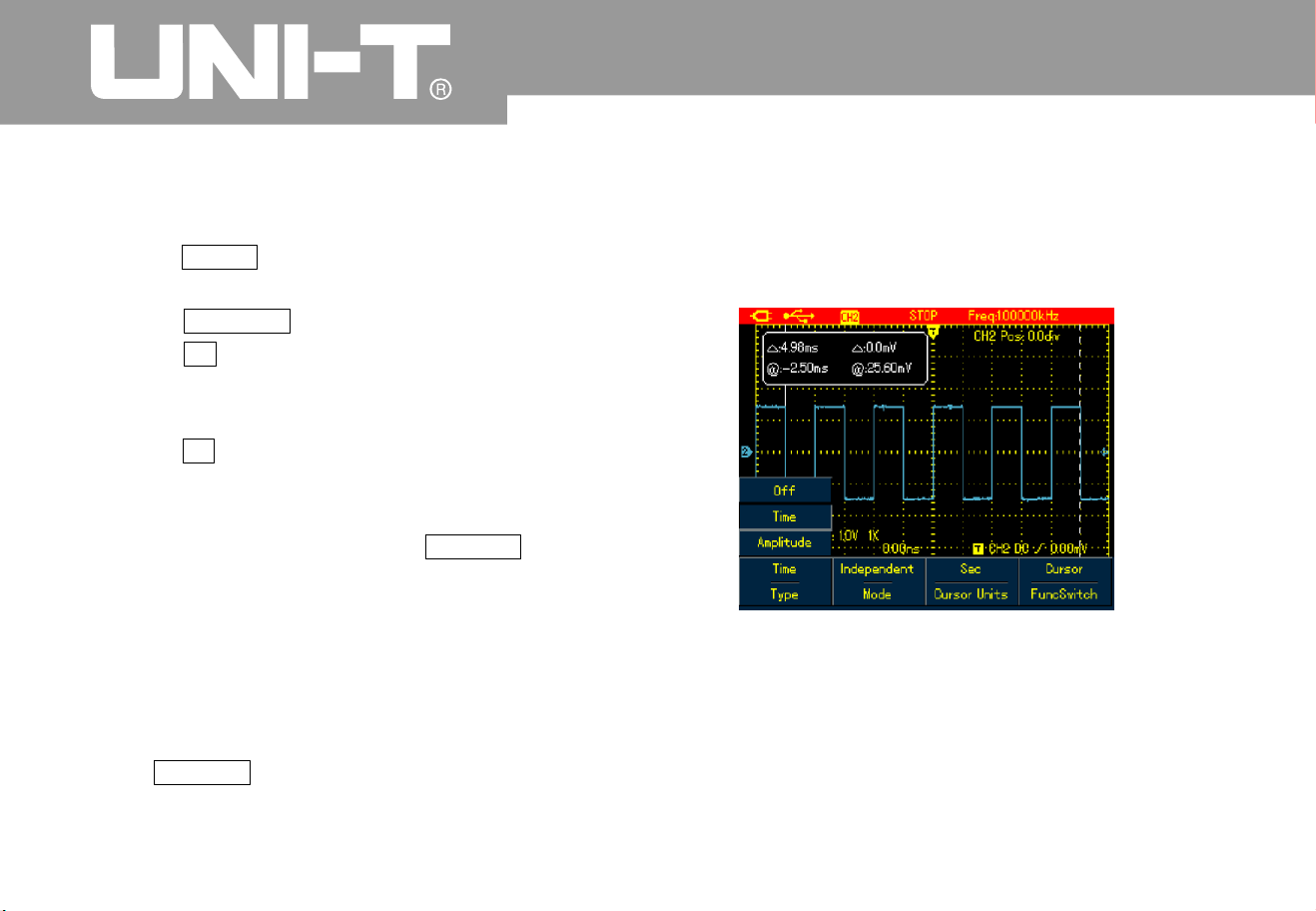
UTD1000L User Manual
Making Cursor Measurements
To make cursor measurements, do the following
:
1. Press SHIFT and shift icon shows on upper
right part of display
.
2. Press CURSOR to access cursor menu
3. Press F2 of UTD1000DL to choose the
channel for cursor measurement (No selectio
n
forUTD1000CL,itdefaultsatCH1
)
4 Press F 1 to set up measuring type
.
There are two options available for measurin
g
Type in cursor menu: Voltage and Time
.
When measuring voltage, use SELECT and
arrow buttons to adjust the locations of two
cursors in order to measure parameter
do the same with measurement
Cursor 1 an
d
Cursor 2 shows simultaneously on the scree
n
use arrow buttons to remove the cursors and
press SELECT to choose and adjust the desired
one Displayed readout is the voltage or time
between two cursors
When the cursor function turns on, measurin
g
values can be automatically shown on upper left
corner of the display
.
Figure 6 -28 Cursor Menu for Time Measurement
ǻ9
ǻW
Voltage/Time Measurement Tips

UTD1000L User M anua l
Table 6-1
5
Figure 6-29 Cursor Menu for Voltage Measurement
Type
Mode
Vertical Unit
Func Switc
h
Time
Independent
T racking
Sec
H
z
Channel
Trigger
Cursor
Use the cursor to measure
the time
Move each cursor
independentl
y
Move two cursors
simultaneously and keep
unchange
d
ǻW
measurement parameter
is time
measurement parameter
is frequenc
y
Use arrow buttons to set
the target to channel
waveform
Use arrow buttons to set
the target to trigger level
Use a rrow
SELECT to select
between Cursor 1 and
Cursor
2
buttons to se
t
thetargettothecursors
press
Menu
Setting
s
Descriptio
n

UTD1000L User Manual
Interfac e Setu
p
To set up the display interface for t he Oscilloscope
,
do the following
:
1. Press SHIFT shift icon shows on uppert
right corner of display
2. Press CONFIGURE to enter into dipla
y
configuration men
u
Type
Mode
Func Switc
h
Voltage
Independent
Tracking
Channel
Trigger
Use the cursor to
measure t he voltage
Move each cursor
independentl
y
Move two cursors
simultaneously and keep
unchange
d
ǻ9
Use arrow buttons to set
the target to channel
waveform
Use arrow buttons to set
the target to trigger level
Use arrow buttons to set
the target to the cursors
,
press SELECT to select
between Cursor 1 and
Cursor
2
Table 6-1
6
Menu
Setting
s
Descriptio
n
Cursor

UTD1000L User M anua l
Tabl e 6-1
7
Utility Setu
p
To set up the display interface for t he Oscilloscope
,
do the following
:
1. Press SHIFT shift icon shows on upper right
cor ner of the dis pla
y
2. Press UTILITY to access Utility menu
.
Menu S etu p show n as in the fol low ing tab le
:
Language
Style
Menu Displa
y
System Inf
o
Multilingual
Classic
,
Traditional
,
Modern
,
White&Black
To select the desired language
To select display style
To set up waiting time before
the manual turns off: 5s 10s
20s Manual Manual the
menu will not turn off
automatically use OK to tur
n
it on/ off
.
—
To display oscilloscope model
,
hardware version, software
version, etc
Menu
Setting
s
Descriptio
n

UTD1000L User Manual
Table 6-1
8
You need to run this operation to avoid any measurement error arising from environment
change To ensure an accurate calibration please power on the Oscilloscope and warm it up for
minutes
The Oscilloscope can automatically adjust its ranges based on the input signal to present
users optimal waveform without any manual interference
.
Key Point
s
Self-Calibration:
Full A utoset
Function menu
Function menu
Model UTD1000C
L
Model UTD1000C
L
SelfCalib
r
SelfCalib
r
Default
Default
Freq Counter
DC Autoset
Clear
Clear
Setting
s
Setting
s
On/Off
On/Off
Descriptio
n
Descriptio
n
The Oscilloscope will calibrate the system automatically
.
The Oscilloscope will calibrate the system automatically
.
The Oscilloscope returns to factory default status
.
The Oscilloscope returns to factory default status
.
Turn on /off trigger frequency counter
.
Turn on/off DC signal self-identification functio
n
Clear saved or recorded w aveforms or settings in the Oscilloscope, etc
Clear saved or recorded waveforms or settings in the Oscilloscope, etc
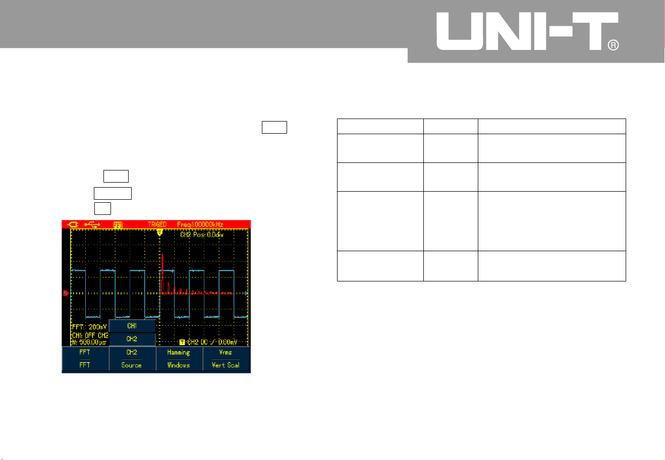
UTD1000L User M anua l
Executing Mathematic Functions
1 For Model UTD1000CL, there is only FFT
operation available refer to following displayed
men
u
To execute F FT operation, do the following
:
1. Press MATH to open math menu
2. Press F1 to turn on FFT operation
.
Figure 6-30 UTD1000CL FFT Operatio
n
Table 6-19
Function menu
FFT
Source
Window
Vertical Unit
Turn on/off FFT functio
n
CH1 is the default channel
for FFT operation
.
Set to Hanning window
Set to Hamming window
Set to Blaclman window
Set to Rectangle window
To set vertical unit to linear
or dBV
CH1
Hannin
g
Hammin
g
Blackma
n
Rectangle
Linear
dBV
O
n
Off
Setting
s
Descriptio
n

UTD1000L User Manual
2 For Model UTD1000DL both FFT and
MATH functions are offered
Math Operation: It is to execute simple
math operations on CH1 and
CH2 waveforms
To perform Math or FFT operation, do the
following
:
1. Press MATH to turn on mathematic menu
2. Press F1 to Set Type to Mat
h
3. Press F1 again to switch to FFT type
Figure 6-32 UTD1000DL FFT Operatio
n
ˇˉhr
Figur e 6-31 UTD 100 0D L M ATH Opera tio
n

UTD1000L User M anua l
Set up Math and FFT menus as follows
:
Table 6-2
0
Type
OFF
Source 1
Source
2
Source
Window
Vertical Unit
Operator
Mat
h
FFT
Setting
s
---
-
Descriptio
n
Turn off M AT
H
functio
n
Set CH1 as Source 1 of Math operatio
n
Set CH2 as Source 1 of Math operatio
n
Set CH1 as Source 2 of Math operatio
n
Set CH2 as Source 2 of Math operatio
n
Set the source to CH1
Set the source to CH
2
Set to Hannin
g
Set to Hammin
g
Set to Blackma
n
Set to Rectangle
window
windo
w
windo
w
windo
w
To set vertical unit to linear or dBV
Sour ce1 Sou rc e
2
Source 1 Source
2
Sour ce 1 S our ce
2
Sour ce 1 S our ce
2
ˇ
ˉ
×
÷
CH1
CH
2
CH1
CH
2
CH1
CH
2
Hannin
g
Hammin
g
Blackma
n
Rectangle
Linear
dBV
ˇ
ˉ
h
r

UTD1000L User Manual
FFT Spectrum Analysis
FFT Operation Tip
s
Select FFT Window
FFT (Fast Fourier Transform algorithm) mode ca
n
convert time domain (YT) into Frequency domai
n
for signal waveform graph, which helps to easil
y
observe signals of following kinds
:
Harmonic component and distortion in the
measurement system
Char acte ri ze noises i n DC s ourc e
A
nalyze the virbratio
n
Signals w ith DC components or bias may cause
error or deviation to FFT waveform components. I
n
order to reduce DC component, you can set
coupling to AC mode. And you can set ACQUIRE
type to AVG to lower down random noise or mixed
overlapped frequency component in repetitive or
single pulse event
.
S
uppose YT waveforms repeats constantly and the
Oscilloscope then performs FFT on limited lengt
h
record. When the period numers are integer, YT
waveform at the start and finish points share same
amplitude values and will not cause an
y
interruption to the waveform. If it is non-integral
,
the start and finish amplitude are different, and
high-frequency transient interruption will happen at
joint points, which is called leakage in frequenc
y
domain. To avoid the leakage, FFT mode will
multiply original waveform with one window
function to force the start and finish values all go to
0. Refer t
o
following windows for details
:
Ɣ
Ɣ
Ɣ

UTD1000L User M anua l
Table 6-21
Term Explanatio
n
FFT Resolution:
NYQUIST Frequenc
y
def ined as Quo ti en t b et wee n s a mp l e rat e a nd oper a tion poin ts . W h en opera ti on points are
fixed, the lower sample rate is, the better FFT resolution will be
For waveforms with highest frequency f, it at least needs to apply 2f sample rate in order
to recreate original waveform It is called NYQUIST principle f is NYQUIST frequency and 2f is NYQUIST
sample rate
.
:
.
.
FFT Window
Hannin
g
Hammin
g
Blackma
n
Rectangle
Feature
s
Comp are d with r e ctangl e type, it has
better amplitude
.
accuracy and less
so for frequency resolutio
n
Freque nc y resol uti o n fo r Hammin g i s
a little bette r tha n t ha t o f Ha nn in
g
.
Offers b est ampl itude a c cu r ac
y
.
an
d
worst for the frequency resolutio
n
Offer best frequency resolu tion, but
worst for the amplitude accuracy. No
big c ha ng e b efo re a nd afte r add i n
g
window function
.
Used to measure sine, periodic and narrowband
random noises
.
Used to measure t ransient or short pulse
after
;
.
and fo
r
signals whose signal levels before and
the event are greatly differen
t
Mainl y for me asur i ng singl e freque ncy signa l s a nd
looking for higher
order harmonics
A
pplicable for measuring transient or short pulse
,
the si gn al l ev els befo re a nd after t he event a r e
app rox im ately equal. And also f or mea su ri ng equa l-
amp litude s in ewave w ith ve ry c l os e freque nc i es
,
broadband random noise with relatively slow
changing spectrum
.
Best Applications

UTD1000L User Manual
Autoset
A
utoset is used to simplify the operations. Press
A
UTO button and then the Oscilloscope will
automatically adjust vertical factor and timebase
range based on the waveform amplitude and
frequency until the waveform displays steadily o
n
the screen. System settings for Autoset functio
n
are shown in the following table
:
Table 6-2
2
Function
s
A
cquire Mode
Display Type
SEC/DIV
VOLT/DIV
Trigger Type
Trigger Level
Trigger couplin
g
Trigger Slope
Trigger Mode
Setting
s
Normal Sample
YT
A
djust based on signal frequenc
y
Adjust based on signal amplitude
Edge
central point of signal
D
C
Rise
A
ut
o

UTD1000L User M anua l
Chapter 7 Troublesh ooting
The Oscillosco pe ca nnot power on
The battery may run out. Try to power on the
Oscilloscope again with use of the power adaptor
.
If the instrument still doesn t work, please contact
UNI- T f or the servi ce
.
The battery may run out. Check if the low batter
y
indicator appears o n the screen. If it does, please
recharge it
.
Make sure channel attenuation factor is
consistent with probe factor on the applied
probe
.
1. Make sure the probe is properly connected to
the connection wire
2. Make sure the connection wire is correctl
y
attached to BNC channel connector
3. Make sure the probe is properly connected to the
tested object.
4. Make sure there are signals generated from the
tested object you can connect the channel
that can produce signals to the suspected
channel and verify the cause
)
5. Restart the acquisition
1. Check if trigger source that has been set up i
n
trigger menu is the same with actual input
channel
2. Check trigger type Edge type is generall
y
selected for common signals use video trigger
type for video signals. Onlywhen proper trigger
The Oscilloscope turns off a few
seconds later a fter powered on:
Measuring voltage amplitude is 10
times larger or smaller than exact
value
No waveform displays after acquirin
g
signals:
The waveform does not displa
y
steadily:

UTD1000L User Manual
type has been set up can the waveform displa
y
steady
.
3. Try to change Coupling to HF R eject to filter out
the high-frequency inteference noise in the
signal
.
1 Check if Trigger Mode in trigge r menu is
Normal or Single and trigger level has gone
beyond waveform ranges. If they are, set trigger
level to the middle or set trigger Mode to
A
UTO
2. Or you can press AUTO to automatically finis
h
the setup mentioned above
1. If AVG number go above 32times, it is normal for
the oscilloscopes to display at a relatively low
rate
.
2. Reduce AVG number
1. It is normal situation, it may b e caused by lower
horizont al ti
mebase, increasing the timebase
can improve the horizontal resolution and the
displa
y
2. If display type is VECTOR ,links between sample
points could probably result in stair-steppin
g
shape. Change display type to D ots can solve
the problem.
There is no display after pres sin
g
down RUN STOP butto
n
The display slows down after havin
g
applied AVG mode for a while:
The waveform display has a stair
-
stepping shape:

UTD1000L User M anua l
Chapter 8 Service and Support
Updating Progra
m
Preparation before Update
Contact UNI-T or log into our website to obtai
n
the latest program package, unzip the package and
apply the Oscilloscope program update system to
update the Oscilloscope so as to ensure your
oscilloscope has the latest version of firmware
issue d alre ady by UNI -T
1. Turn on your oscilloscope, press CONFIGURE
button and select system information option so
as to obtain details about the Oscillosocpe
model, hardware version, software version, etc
.
2. Make sure the program package you get from
UNI T company or website has the same
model number and hardware version with the
Oscilloscope to be updated. The version should
be higher than the current version
.
1.The update program must have the same product
model with that of your oscilloscope
.
2. The update program must be consistent wit
h
your oscilloscope on hardware versio
n
3. The update program version must be higher than
or equal to that of your oscilloscope
.
1. Properly install the Oscilloscope software into
your PC as instructed in communicatio
n
software users manual
2.Copy the program package(extension is upp
into PC You can download from UNI-T website
and contact UNI-T company directly to get the
package
.
3.Connect the Oscil
loscope to PC with USB cable,
then click to run the software choose
corresponding oscilloscope model and click
ENTER in pop-up interface, the software
interface will appear. Click Connect butto
n
on the interface to begin communicatio
n
between PC and the Oscilloscope. With this
connection finished, there will be an indicatio
n
that USB has been connected successfully
.
Ǐǐ
Ǐǐ
Update Conditio n
s
Program Update

UTD1000L User Manual
Figure 8-1 Connect to P
C
4. Choose from the software menu Actio
n
Program Update then select the copied
program package on dialogue box and confirm OK
.
The Oscilloscope then begins the update and
reads The Oscilloscope is preparing the update
,
please wait
5. The Oscilloscope will read update has
succeeded! on the screen after the update has
finished Do not do any operation on the
Oscilloscope at the moment please repower it on
to complete the program update
.
Ǐǐ
Ǐǐ
Ā
Ăā
ĺ
Figu re 8-2 Pr ogra m
Update
”
.
,

UTD1000L User M anua l
Notes
:
1. When the program package doesn t adapt to the Oscilloscope, PC reads the update f ile is incorrect
2. If the Oscilloscope was disconnected to PC or powered off or PC has been shut down durin
g
'
“
,
!
”
,
.
,
.
please
check then the Oscilloscope then stops the update and keep s the previous program version
unchanged
update the
update w ould stop and leave the previous program unchanged

UTD1000L User Manual
Chapter 9 Appendixe
s
Appendix A Technical Specifications
Unless otherwisef specified, the technical specifications are all applicable for 10 probe and
UTD1025L Oscilloscope First of all the Oscilloscope must satisfy two following conditions in order
to mee those specifications
The Oscilloscope must run continuously for more than 30 minutes in regulated working temperature
.
Users have to execute self-calibration procedure in UTILITY menu if operating temperature is 5 or
above higher than specified range All specifications are warranted except items marked with
Typical
h
Āā ć
Āā
Ŷ
Ŷ
Technical Specifications:
Oscilloscope
Acquisition mode
A
cquisi ti on mode
A
cquisition rate
A
cquisitio
n
A
VG v al ue
Real time acquisitio
n
UTD1025CL UTD1050CL 200MS/s
UTD1025DL 1050D
L
/
UTD MS s25
0
A
cquisitio
n
, Peak Detect, AVG, Fast Acquisition UTD1000DL
(
A
ll channels can acquire simultaneously up to N times, N can be selected from 2 4
8163264128 25
6
,
,,,,
an
d

UTD1000L User M anua l
Input
Horizontal
Input Couplin
g
Waveform Interpolatio
n
Input Impedance
Record Lengt
h
Probe Attenuation Factor
Memory Dept
h
Max.Input Voltage
Max.Input Voltage
Interchannel Delay typical
(
Sample Rate and Delay
.
A
ccurac
y
Interval Time
Measuring Accurac
y
Full BW
(
÷
(
Ƹ
DC AC GNDǃǃ
sin(x)/x
1 2% 21 3PF in parallel
±±
Ȃ
ȍ
ˈ
UTD1000CL 1.5M 1000DL 3M
:
,
UTD
1X,10X,100X,1000X
12K
300V DC AC Input Impedance˄ˇ ǃ ˅
,
Pea
k
1M
ȍ
UTD1025CL UTD1025DL 10ns/div-50s/di
v
UTD1050CL UTD1050DL Stepping in 1-2-
5
:
:/-
550
ns div s di
v
50ps
±
(
50ppm( any time interval 1ms
)
SINGLE sampling interval time ppm readings ns
16AVGs sampling interval time ppm readings ns
:
(++.
:
(
f
ff
150X0
6
1 100 X 0 4η ˅f

UTD1000L User Manual
Vertical
A
/D Converter(A/D
)
Vertical Scale(V/di
v
)
Offset Ranges
A
nalog Bandwidt
h
LF Response
A
C Coupled dB
(
-
,
-
3
Rise Time
DC Gain Accurac
y
DC Measurement
A
ccuracy(AVG mode)
Voltage Differnce(Ƹ
÷
)
(
)
Measuring Accuracy AVG
Mode
8-bit resolutio
n
5mV/div 20V/di
v
(
at BNC or
t
)
5mV/div 100mV/div 1.2V 200mV/div 1V/div 24V
2V/div 20V/div 240V
˗˗
˗
:
±
:
±
:
±
UTD1025CL UTD1025DL 25MHz UTD1050CL UTD1050DL MH
z
˗ 5
0
İ10Hz(at BNC
)
UTD1025CL UTD1025DL 14ns UTD1050CL UTD1050DL 7ns
:
˗
For ver ti al Sens it ivit y 5mV /di v 4%
vertial Sensitivity from 10mV/div 20V/div 3%
:
±
(
:
±
(
Normal or AVG
Normal or AVG
Where vertical offset equals zero and N16
:
Readings div mV and select mV di
v
3 Readings+0.1div+1mV) and select 10mV/div 20V/di
v
Readings+0.1div+1mV)and select bewteen 10mV/div 20V/div
.
Where vertival offset does not equal to zero and N16
:
A
dd 2mV if setting between 5mV/div to 200mV/div Add mV if settings
from mV div to V di
v
±
(
×
++
1
)
/
±
(
×
±
(
;
//
4%
5
%
%
5
0
0.1
3
200 2
0
h
±
[
×
(+ )+(
×
)]+
Readings Vertical offset value Vertical offset Value div3% 1% 0.2
Under same settings and ambient conditions, calcula
readings+0.05div)
WH YROWDJH GLIIHUHQFHǻ9
between any two points just after capturing 16 wavforms and working out
average values. Equation
:
±
(
×
3%

UTD1000L User M anua l
Trigge
r
Trigger Sensitivit
y
T rigger Level Range
Pre-Trigger
Hold-Off Range
Edge Trigg e
r
Edge Type
Pulse Width Trigge
r
Trig ger Mod e
Pulse Width Range
Video Tri gge
r
Trigge r Sen siti vit
y
Video typical
(,
Video For mat an d
Line/Field Frequenc
y
Slope Trigge
r
Trigger Conditions
Slew Rate
İ1di
v
±
10di
v
from screen center poin
t
Normal/Sweep Mode, Pre-trigger/Delay Trigger, Pre-trigger D epth Adjustable
100ns - 1.5s
Rise
,
fall
(,,) ,(,,)
˚˘˙ ˚˘˙Positive Pulse Width Negative Pulse Width
20ns-10s
2divs Peak-to-Peak Value
Support standard PAL 525 NTS
C
1625PA
L
,(
(
NTSC and line numbers from and
1
˘˚˙
,
40pV/ȝs1.6kV/ȝs

UTD1000L User Manual
Measurement
s
Manual Mode
Window
A
uto Measurements
Customized Parameter Measurement
Mathematics
Storage
Waveform Recordin
g
Up to 4 t ypes a t a ti me
UTD1000CL FFT UTD1000DL
:
;
Math and FFT
Screens: 10sets Waveforms: 20 sets, Settings:20 types
,
;
Store 5 sets of waveform records. UTD1000CL: recording 300
screens 1000D
L
;
UTD recording screens15
0
A
uto Mode
Sample Points
Phase Difference
Cursor
FFT
NYQUIST Patter
n
(
UTD1000D
L
&XUVRU 9ROWDJH 'LIIHUHQFHǻ9 &XUVRU 7LPH 'LIIHUHQFHǻ7
ǻ7 UHFLSURFDO+]ǻ7
Hanning,Hamming,Biackman,Rectangular
UTD1000CL: Peak Max, Min,Top Point
,
Bottom Point, Middle, Overshoot, Preshoot
,
Rise Time, Fall Time, Positive
1000D
L
-- ,
,
,, &
,& ,
:
:
,,
to Peak Amplitude
AVG RMS
Frequency period Negative Pulse
Width P ositive Negative Duty Cyc le total types
UTD apartfrom types the model offer an other
three pa rameters Rise Delay Fall Delay Phase
1
9
1
9
Cursor allowed to display in auto mode
1024 points
±
3degrees
Multimete
r
The specified accuracy is valid over the temperature range 18 to 2
8
A
dd 10 % of specified accuracy for each degree C below 18 or above 2
8
℃℃
℃℃

UTD1000L User M anua l
DC Voltage
:
Input Impedance
:
Max.Input Voltage: DC400V
A
C Voltage
:
Input Impedance
:
Max.Input Voltage: 400V AC RMS
Frequency Range 40Hz ~ 400Hz
.
Display: RMS of sinewave
:
10M
ȍ
10M
ȍ
DŽ
UTD1000CL DC Current
Max. Input DC Current DC10
A
UTD1000CL AC Current
Max.Input AC Current: AC 10A RMS
Frequency Range 40Hz 400H
z
:
 ̄
Range
Range
Resolutio
n
Resolutio
n
Resolutio
n
0.1ȝ
A
0.1ȝ
A
0.1m
A
0.1m
A
10ȝ
A
10ȝ
A
10m
A
10m
A
Resolutio
n
Range
Range
400.0mV
400.0mV
0.1m
v
0.1m
v
350 A
ˊ0ȝ
350 A
ˊ0ȝ
4.000V
4.000V
1m
v
1m
v
40.00mA
40.00mA
400 0mA
.
400 0mA
.
40.00V
40.00V
1m
v
0
1m
v
0
400.0V
400.0V
100m
v
100m
v
10.00
A
Measure with UT-M0
7
10
A
(
)
current divide
r
module
10.00
A
Measure with UT-M0
7
10
A
(
)
current divide
r
module
A
ccurac
y
A
ccurac
y
A
ccurac
y
f(
)
1.2% 5 digitsˇ
f(
)
2% 5 digitsˇ
f
ˇ
(1% 5
)
digits
f
ˇ
(1 5% 5
)
. digits
f(
5
1. % 5 digits
)
ˇ
f(
5
2. % 5 digits
)
ˇ
A
ccurac
y
f
ˇ
1%
5
digits(
)
f(
)
1.2% 5 digitsˇ

UTD1000L User Manual
UTD1000DL DC Current
Max. In put DC Curr en t DC 4
A
UTD1000DL AC Current
Max.Input AC Current: AC 4A RMS
Frequency Range 40Hz 400H
z
:
:
: ̄
Range
Range
999.9ȝ
A
Measure with UT-M1
0
(
mA current module
999.9ȝ
A
Measure with UT-M1
0
(
mA current module
40.00m
A
Measure with UT-M1
0
(
mA current module
40.00m
A
Measure with UT-M1
0
(
mA current module
400.0m
A
Measure with UT-M1
0
mA current module
(
400.0m
A
Measure with UT-M1
0
mA current module
(
4.00
A
Measure with UT-M0
4
4A current divider
module
(
)
4.00
A
Measure with UT-M0
4
4A current divider
module
(
)
A
ccurac
y
A
ccurac
y
±
(
1.2% 5digits
)
ˇ
±
(
2% 5digits
)
ˇ
±
(
1% 5digits
)
ˇ
±
(
% 5digits
)
ˇ1.
5
±
(
1.5% 5digits
)
ˇ
±
(
.5% 5digits
)
ˇ2
Resolutio
n
Resolutio
n
0.1ȝ
A
0.1ȝ
A
10ȝ
A
10ȝ
A
0.1m
A
0.1m
A
1
0
A
m
1
0
A
m

UTD1000L User M anua l
Resistance
Capacitance
Diode
:
Voltage Readout: 0V~1.5V
Continuity Test
:
Resistance value for d iscontinuity: the
beeper doesn t sound
Resistance value f or good circuit continuity:7
0
continuous beepin
g
,
'
;
˚
ˈ
75
ȍ
ȍ
Range
Range
400.0
ȍ
51.20nF
4.000kȍ
512.0nF
40.00kȍ
5.120uF
400.0kȍ
51.20ȝF
4.000M
ȍ
100ȝF
40.00M
ȍ
A
ccurac
y
A
ccurac
y
f
ˇ
1.2%
5
digits(
)
±
(
3% 5digits
)
ˇ
f
ˇ
1.5%
5
digits(
)
Displa
y
Interface
Displat Type
Standar
d
Display Resolutio
n
Optional
Displ ay Colo r
Waveform Displa
y
Zone
Backlight
Brightness
Backlight Intensit
y
Language
3.5inch, TFT
LCD
UTD1000CL UT M07(10A current
divider module pcs one USBcable
UTD1000DL UT M04 4A current divider
module), 1pcs, one UT-M10(mA current
module), 1pcs USB cable pcs
:
-
), ;
:-
;
1
1
320Horizontal RGB 24
0
×
×
Vertical pixels
Color/Black&White
Horizontal: 12div, 25dot/di
v
;
:
,
/
Vertical div dot div
82
5
A
djustable
300nit
Multilingual
---
Resolutio
n
Resolutio
n
0.1
ȍ
10pF
100pF
1
ȍ
10
ȍ
1nF
10
ȍ
0
10nF
1k
ȍ
1ȝF
1k
ȍ
0

UTD1000L User Manual
Battery 7.4 V mA rechargeable lithium
batter UTD1000CL hour battery life
UTD1000DL hour battery life
:
;
:
:-
360
0
8
6
Power Adapto
r
Mains Voltage
Output Voltage
Output Voltage
100~220 V AC rms,45~440H
z
9VD
C
4
A
Environment
Temperature
Cooling Metho
d
A
ltitude
Humidit
y
Operating: 0 4
0
ć ć
Non-operation: 6
0
ć ć2
0
Naturally cooled dow
n
Operating:3 000m
,
Naturally cooled down 5 000m
1
,
ˇć
ˇćˇć
35 90%
35 40 60%
Mechanic specifications
Dimensions
(
Reference Data
Weight
(
Net Weight
199mm 118mm 49mm
hh
Packing not included
Packing Include
d
0.9k
g
2.3k
g
IP Degree
Calibration Perio
d
IP2X
one time for each year

UTD1000L User M anua l
Appendix B Maintenance
1.General Service
Clean in
g
2. Stor ing the Oscil loscope
3. Charging B atteries
Do not store or place the Oscilloscope in places
that may get its LCD exposed to direct sunshine for
a long time. Do not let spray agent, liquid and
solvent stick onto the Oscilloscope or probe so as
to avoid any damage to the Oscilloscope or probe
Check the Oscilloscope and its probe as actual
operation requires. Clean the Oscilloscope surface
as follows
:
1. Clean dust on the Oscilloscope and probe
surface with soft cloth. Avoid any scratch to
LCD transparent protective layer
.
2. Clean with soft cloth damped with water or mild
agent, no water drop is allowed to occur. Do not
use any corrosives or abrasives. Disconnect the
power supply before cleaning
.
Warning: To avoid any short circuit or eve
n
personal injury resulted from residual water, please
make sure the Oscilloscope is totally dry before
powering it o
n
To store the Oscilloscope for a long term, you
need to charge the batteries before storing it
.
The battery may not be fully charged durin
g
the delivery, it must take four hours to fully charge
the battery. The battery can work for 8hours after
full charge
.
When powered by the battery, t he Oscilloscope
indicates battery working status on the upper part
of screen.battery indicator
s may include
:
A
n
d
con means there is only five
minutes left before the Oscilloscope powers off
.
Please connect
the power adaptor to the
Oscilloscope if you want to charge the batter
y
and us e the Oscillosocpe at the same time

UTD1000L User Manual
Caution:
Note:
Replacing Lithium Batttery Pack
To avoid over-heating when charging the
battery, environment temperature shouldn t
exceed allowable rated value(0 40
There is no danger involved even the
Oscilloscope has been connected to the charger
for a long time, for instance, during the whole
weekend, for the Oscilloscope can automaticall
y
switch into very slow charging status
.
The battery pack doesn t need the replacement
under general circumstances. If necessary please
have the battery pack replaced by qualified
personnel and use new battery with the same
specifications
.
'
+)
'
,
ć ć

UTD1000L User M anua l
This user manual may be revised without prior notice
.

114