

© 2014 STANLEY Black & Decker, Inc.
New Britain, CT 06053
U.S.A.
66864 8/2018 Ver. 16
USER MANUAL
Safety, Operation and Maintenance
CS05/CS06
HYDRAULIC
CHAIN SAW

CS05/CS06 User Manual ◄ 3
SAFETY SYMBOLS .................................................................................................................................................4
SAFETY PRECAUTIONS .......................................................................................................................................5
ELECTRICAL PRECAUTIONS ............................................................................................................................... 7
TOOL STICKERS & TAGS ......................................................................................................................................9
HOSE TYPES ........................................................................................................................................................10
HOSE RECOMMENDATIONS .............................................................................................................................. 11
HTMA / EHTMA REQUIREMENTS ......................................................................................................................12
OPERATION ..........................................................................................................................................................13
TOOL PROTECTION & CARE ..............................................................................................................................18
TROUBLESHOOTING ..........................................................................................................................................19
SPECIFICATIONS .................................................................................................................................................20
CS05/CS06 PARTS ILLUSTRATION ....................................................................................................................21
CS05/CS06 PARTS LIST .......................................................................................................................................22
UNDERWATER TOOLS DEPTH GUIDELINE ..................................................................................................... 24
TABLE OF CONTENTS
SERVICING: This manual contains safety, operation and routine maintenance instructions. STANLEY Infrastructure
recommends that servicing of hydraulic tools, other than routine maintenance, must be performed by an authorized
and certied dealer. Please read the following warning.
To ll out a product warranty validation form, and for information on your warranty,
visit www.stanleyinfrastructure.com and select the Company tab > Warranty.
Note: The warranty validation record must be submitted to validate the warranty.
SERIOUS INJURY OR DEATH COULD RESULT FROM THE IMPROPER REPAIR OR
SERVICE OF THIS TOOL.
REPAIRS AND / OR SERVICE TO THIS TOOL MUST ONLY BE DONE BY AN
AUTHORIZED AND CERTIFIED DEALER.
For the nearest certied dealer, call STANLEY Infrastructure at (503) 659-5660 and ask for a Customer Service Representative.
4 ► CS05/CS06 User Manual
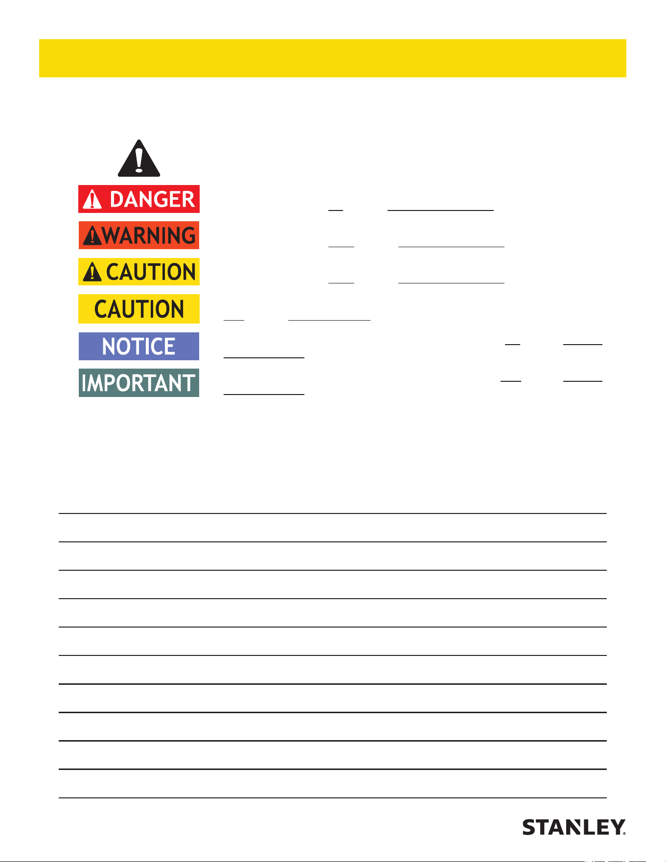
Always observe safety symbols. They are included for your safety and for the protection of the tool.
LOCAL SAFETY REGULATIONS
Enter any local safety regulations here. Keep these instructions in an area accessible to the operator and
maintenance personnel.
Safety symbols and signal words, as shown below, are used to emphasize all operator, maintenance and repair
actions which, if not strictly followed, could result in a life-threatening situation, bodily injury or damage to equipment.
This is the safety alert symbol. It is used to alert you to potential personal injury
hazards. Obey all safety messages that follow this symbol to avoid possible
injury or death.
This safety alert and signal word indicates an imminently hazardous situation
which, if not avoided, will result in death or serious injury.
This safety alert and signal word indicates a potentially hazardous situation
which, if not avoided, could result in death or serious injury.
This safety alert and signal word indicates a potentially hazardous situation
which, if not avoided, could result in death or serious injury.
This signal word indicates a potentially hazardous situation which, if not avoided,
may result in property damage.
This signal word indicates a situation which, if not avoided, will result in damage
to the equipment.
This signal word indicates a situation which, if not avoided, may result in damage
to the equipment.
SAFETY SYMBOLS

CS05/CS06 User Manual ◄ 5
Tool operators and maintenance personnel must always
comply with the safety precautions given in this manual
and on the stickers and tags attached to the tool and
hose.
These safety precautions are given for your safety.
Review them carefully before operating the tool and
before performing general maintenance or repairs.
Supervising personnel should develop additional
precautions relating to the specic work area and local
safety regulations. If so, place the added precautions in
the space provided in this manual.
The model CS05/CS06 Hydraulic Chain Saw will provide
safe and dependable service if operated in accordance
with the instructions given in this manual. Read and
understand this manual and any stickers and tags
attached to the tool and hose before operation. Failure
to do so could result in personal injury or equipment
damage.
• The operator must start in a work area without
bystanders. Flying debris can cause serious injury.
• Do not operate the tool unless thoroughly trained
or under the supervision of an instructor. Establish
a training program for all operators to ensure safe
operation.
• Always wear safety equipment such as goggles, ear
and head protection and safety shoes at all times
when operating the tool. Use gloves and aprons
when necessary.
• The operator must be familiar with all prohibited work
areas such as excessive slopes and dangerous
terrain conditions.
• Do not inspect, clean or replace any parts if the
hydraulic power source is connected. Do not inspect
or clean the tool while the hydraulic power source is
connected. Accidental engagement of the tool can
cause serious injury.
• Always connect hoses to the tool hose couplers
before energizing the hydraulic power source. Be
sure all hose connections are tight and are in good
condition.
• Do not operate the tool at oil temperatures above
140 °F/60 °C. Operation at higher temperatures can
cause higher than normal temperatures at the tool
which can result in operator discomfort.
• Do not operate a damaged, improperly adjusted or
incompletely assembled chain saw. Be sure that
the chain stops moving when the control trigger is
released.
• Never wear loose clothing that can become
entangled in the working parts of the tool.
• Keep all parts of your body away from the chain saw
and maintain proper footing and balance at all times.
• WARNING: Some dust created by power sanding,
sawing, grinding, drilling, and other construction
activities contains chemicals known to the State
of California to cause cancer, birth defects or
other reproductive harm. Some examples of these
chemicals are:
• Lead from lead-based paints,
• crystalline silica from bricks and cement
and other masonry products, and
• arsenic and chromium from chemically-
treated lumber.
Your risk from these exposures varies, depending
on how often you do this type of work. To reduce
your exposure to these chemicals: work in a well
ventilated area, and work with approved safety
equipment, such as those dust masks that are
specially designed to lter out microscopic particles.
Protect yourself and those around you. Research
and understand the materials you are cutting.
Follow correct safety procedures and comply with
all applicable national, state or provisional health
and safety regulations relating to them, including,
if appropriate arranging for the safe disposal of the
materials by a qualied person.
• Do not rely exclusively upon the safety devices built
into the saw. As a chain saw user, several steps
must be taken to keep your cutting jobs free from
accidents or injury.
– With basic understanding of kickback, you can
reduce or eliminate the element of surprise.
Sudden surprise contributes to accidents.
– To avoid personal injury or equipment damage,
all tool repair, maintenance and service must
only be performed by authorized and properly
trained personnel.
– Keep a good rm grip on the saw with both
hands, the right hand on the rear handle and
the left hand on the front handle when operating
the saw. Use a rm grip with thumbs and ngers
encircling the chain saw handles. A rm grip will
SAFETY PRECAUTIONS

6 ► CS05/CS06 User Manual
help reduce kickback and maintain control of
the saw. Do not let go.
– Make sure the area in which you are cutting
is free of obstructions. Never allow the nose
of the guide bar to contact the log, branch or
any obstruction that can be accidently hit while
operating the saw.
– Never start the tool while it is lying on the ground.
– Cut at rated operating speeds (gpm).
– Do not overreach or cut above shoulder height.
– Follow the manufacturer’s sharpening
andmaintenance instructions for the saw chain.
– Only use replacement bars and chains
specied by STANLEY. Chains must meet the
requirements of ANSI B175.1 for low kickback
performance.
• Always be well rested and mentally alert before
operating the chain saw.
• Do not allow other persons to be near the chain
saw when starting or cutting with the saw. Keep
bystanders and animals out of the work area.
• Do not starting cutting until you have a clear work
area, secure footing and a planned escape path
from a falling tree.
• Carry the saw with the unit de-energized and the bar
and chain to the rear of your body.
• Use extreme caution when cutting small size brush
and saplings. Twigs may catch the saw chain and
be whipped toward the operator or pull the operator
o balance.
• When cutting a limb that is under tension, be alert
for springback so that you will not be struck when
the tension on the limb is released.
• Keep the handles dry, clean and free of oil.
• Do not operate a chain saw while in a tree, unless
you have been specially trained to do so.
• When using tools near energized transmission lines,
be sure to use only hoses labeled and certied as
non-conductive.
• Turn o the power unit or move the hydraulic control
valve to neutral before setting the saw down.
• Use a guide bar scabbard when transporting the
saw.
• Know the location of buried or covered electrical
services before starting work.
• To avoid personal injury or equipment damage,
all tool repair, maintenance and service must only
be performed by authorized and properly trained
personnel.
SAFETY PRECAUTIONS

CS05/CS06 User Manual ◄ 7
The following guidelines must be followed to prevent
accidental contact with overhead electrical conductors
and/or communication wires and cables. (ref. ANSI
Z133.1-2000)
Working in Proximity to Electrical Hazards:
An inspection shall be made by a qualied arborist to
determine whether an electrical hazard exists before
climbing, or otherwise entering, or performing work in
or on a tree.
Only qualied line-clearance arborists or qualied
line-clearance arborist trainees shall be assigned to
work where an electrical hazard exists. Qualied line-
clearance arborist trainees shall be under the direct
supervision of qualied line-clearance arborist.
A second qualied line-clearance arborists or line-
clearance arborist trainees shall be within vision or voice
communication during line-clearing operations aloft
when line-clearance arborists or line-clearance arborist
trainees must approach closer than 10 feet (3.05 meters)
to any energized electrical conductor in excess of 750
volts (primary conductor) or when:
1. Branches or limbs being removed cannot rst be
cut (with a pole pruner/pole saw) to suciently
clear electrical conductors, so as to avoid contact.
2. Roping is required to remove branches or limbs
from such electrical conductors. This does not
apply to individuals working on behalf of, or
employed by, electrical system owners/operators
engaged in line-clearing operations incidental to
their normal occupation.
Qualied line-clearance arborists and line-clearance
arborist trainees shall maintain minimum approach
distances from energized electrical conductors in
accordance with Table 1.
All other arborists shall maintain a minimum approach
distance from energized electrical conductors in
accordance with Table 2.
Branches hanging on an energized electrical
conductor shall be removed using non-conductive
equipment.
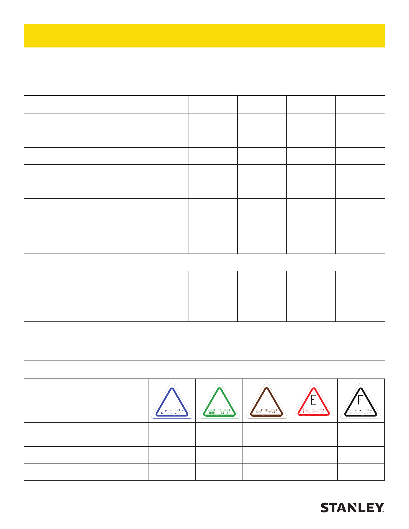
Table 1 – Minimum approach distances from energized conductors for qualied line-clearance arborists and
qualied line- clearance arborist trainees.
Nominal Voltage
(kV phase-to-phase)
Includes 1910.269
elevation factor,
sea level to 5000 ft
1
Includes 1910.269
elevation factor,
5001 – 10,000 ft
1
Includes 1910.269 elevation
factor, 10,000 – 14,000 ft
1
ft–in m ft–in m ft–in m
0.05 to 1.0 Avoid contact Avoid contact Avoid contact
1.1 to 15.0 2–04 0.71 2–08 0.81 2–10 0.86
15.1 to 36.0 2–09 0.84 3–02 0.97 3–05 1.04
36.1 to 46.0 3–00 0.92 3–05 1.04 3–09 1.14
46.1 to 72.5 3–09 1.14 4–03 1.30 4–07 1.40
72.6 to 121.0 4–06 1.37 5–02 1.58 5–07 1.70
138.0 to 145.0 5–02 1.58 5–11 1.80 6–05 1.96
161.0 to 169.0 6–00 1.83 6–10 2.08 7–05 2.26
230.0 to 242.0 7–11 2.41 9–00 2.75 9–09 2.97
345.0 to 362.0 13–02 4.02 15–00 4.58 16–03 4.96
500.0 to 550.0 19–00 5.80 21–09 6.63 23–06 7.17
765.0 to 800.0 27–04 8.34 31–03 9.53 33–10 10.32
1
Exceeds phase-to-ground; elevation factor per 29 CFR 1910.269.
ELECTRICAL PRECAUTIONS

8 ► CS05/CS06 User Manual
Table 2 – Minimum approach distances to energized conductors for persons
other than qualied line-clearance arborists and qualied line-clearance
arborist trainees.
Nominal Voltage
kV phase-to-phase
1
Distance
ft-in m
0.0 to 1.0 10–00 3.05
1.1 to 15.0 10–00 3.05
15.1 to 36.0 10–00 3.05
36.1 to 50.0 10–00 3.05
50.1 to 72.5 10–09 3.28
72.6 to 121.0 12–04 3.76
138.0 to 145.0 13–02 4.00
161.0 to 169.0 14–00 4.24
230.0 to 242.0 16–05 4.97
345.0 to 362.0 20–05 6.17
500.0 to 550.0 26–08 8.05
785.0 to 800.0 35–00 10.55
1
Exceeds phase-to-ground.
The tie-in position should be above the work area and
located in such a way that a slip would swing the arborist
away from any energized electrical conductors or other
identied hazard.
While climbing, the arborist should climb on the side of
the tree that is away from energized electrical conductors
as required in Tables 1 and 2.
Footwear, including lineman’s overshoes, having
electrical-resistant soles, shall not be considered as
providing any measure of safety from electrical hazards.
Rubber gloves, with or without leather or other protective
covering, shall not be considered as providing any
measure of safety from electrical hazards.
Ladders, platforms and aerial devices, including
insulated aerial devices, shall be subject to minimum
approach distances in Table 1 and 2.
Aerial devices and attached equipment (such as
chippers) contacting energized electrical conductors
shall be considered energized. Contact shall be avoided,
except where emergency rescue procedures are being
carried out. Emergency rescue should be performed in
accordance with 4.3.
STORM WORK AND EMERGENCY
CONDITIONS-LINE CLEARANCE
Line clearance shall not be performed during adverse
weather conditions such as thunderstorms, high winds
and snow and ice storms.
Qualied line-clearance arborists and qualied line-
clearance arborists trainees performing line clearance
in the aftermath of a storm or under similar conditions
shall be trained in the special hazards associated with
this type of work.
Line-clearance operations shall be suspended when
storm work or emergency conditions develop involving
energized electrical conductors. Electrical system
owners/operators shall be notied immediately.
ELECTRICAL PRECAUTIONS
CS05/CS06 User Manual ◄ 9
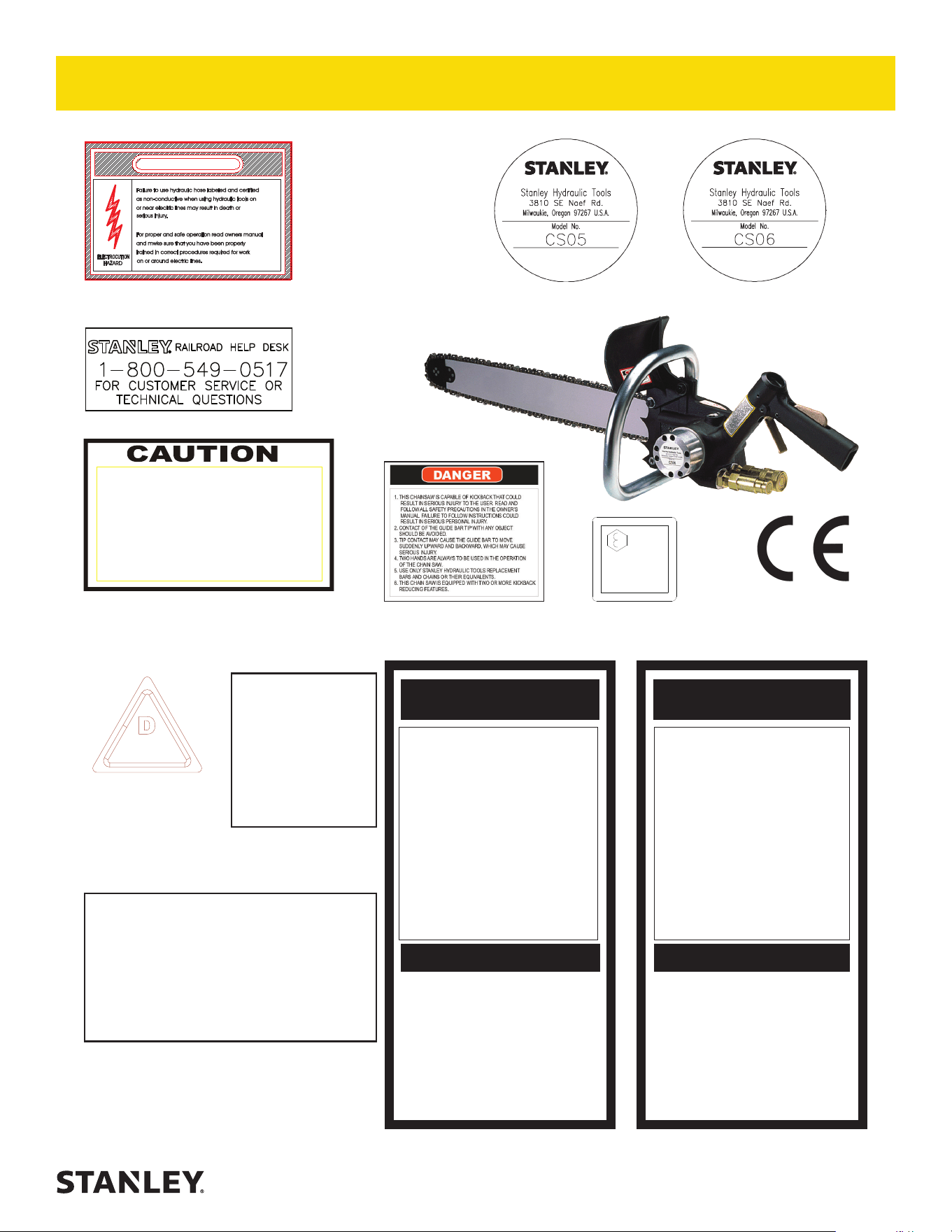
28323
CE Decal
(CE Models Only)
D
30 LPM @ 138 BAR
EHTMA CATEGORY
11207
Circuit Type D Decal
(CE Models Only)
Failure to use hydraulic hose labeled and certified
as non-conductive when using hydraulic toolson
or near electric lines mayresultin deathor
Forproper and safe operationread ownersmanual
and mwke surethat you have been properly
trained in correct procedures required for work
serious injury.
on or around electric lines.
ELECTROCUTION
HAZARD
DANGER
12412
Electrical Warning Decal
03782
GPM Decal – CS05 Model
03786
GPM Decal – CS06 Model (Not Shown)
4-6 GPM / 15-22 LPM
DO NOT EXCEED 2000 PSI / 140 BAR
DO NOT EXCEED SPECIFIED FLOW OR PRESSURE
USE CLOSED-CENTER TOOL ON CLOSED-CENTER
SYSTEM. USE OPEN-CENTER TOOL ON OPEN-CENTER
SYSTEM. CORRECTLY CONNECT HOSES TO TOOL “IN”
AND “OUT” PORTS. IMPROPER HANDLING, USE OR OTHER
MAINTENANCE OF TOOL COULD RESULT IN A LEAK, BURST
OR OTHER TOOL FAILURE. CONTACT AT A LEAK OR BURST
CAN CAUSE OIL INJECTION INTO THE BODY. FAILURE TO
OBSERVE THESE PRECAUTIONS CAN RESULT IN SERIOUS
PERSONAL INJURY.
17784
101 Sound Level Decal
(CE Models Only)
107
Lwa
13907
Kickback Warning Decal
The safety tag (P/N 15875) at right is attached to
the tool when shipped from the factory. Read and
understand the safety instructions listed on this tag
before removal. We suggest you retain this tag and
attach it to the tool when not in use.
NOTE
THE INFORMATION LISTED ON THE
STICKERS SHOWN, MUST BE LEGIBLE AT ALL
TIMES.
REPLACE DECALS IF THEY BECOME WORN
OR DAMAGED. REPLACEMENTS ARE
AVAILABLE FROM YOUR LOCAL STANLEY
DISTRIBUTOR.
SAFETY TAG P/N 15875 (Shown smaller then actual size)
DANGERDANGER
READ OPERATION MANUAL AND
SAFETY INSTRUCTIONS FOR THIS
TOOL BEFORE USING IT.
USE ONLY PARTS AND REPAIR
PROCEDURES APPROVED BY
STANLEY AND DESCRIBED IN THE
OPERATION MANUAL.
TAG TO BE REMOVED ONLY BY
TOOL OPERATOR.
SEE OTHER SIDE
1. FAILURE TO USE HYDRAULIC HOSE LABELED AND CERTI-
FIED AS NON-CONDUCTIVE WHEN USING HYDRAULIC
TOOLS ON OR NEAR ELECTRICAL LINES MAY RESULT IN
DEATH OR SERIOUS INJURY.
BEFORE USING HOSE LABELED AND CERTIFIED AS NON-
CONDUCTIVE ON OR NEAR ELECTRIC LINES BE SURE THE
HOSE IS MAINTAINED AS NON-CONDUCTIVE. THE HOSE
SHOULD BE REGULARLY TESTED FOR ELECTRIC CURRENT
LEAKAGE IN ACCORDANCE WITH YOUR SAFETY DEPART-
MENT INSTRUCTIONS.
2. A HYDRAULIC LEAK OR BURST MAY CAUSE OIL INJECTION
INTO THE BODY OR CAUSE OTHER SEVERE PERSONAL
INJURY.
A. DO NOT EXCEED SPECIFIED FLOW AND PRESSURE
FOR THIS TOOL. EXCESS FLOW OR PRESSURE MAY
CAUSE A LEAK OR BURST.
B. DO NOT EXCEED RATED WORKING PRESSURE OF
HYDRAULIC HOSE USED WITH THIS TOOL. EXCESS
PRESSURE MAY CAUSE A LEAK OR BURST.
C. CHECK TOOL HOSE COUPLERS AND CONNECTORS
DAILY FOR LEAKS. DO NOT FEEL FOR LEAKS WITH
YOUR HANDS. CONTACT WITH A LEAK MAY RESULT
IN SEVERE PERSONAL INJURY.
IMPORTANT
D. DO NOT LIFT OR CARRY TOOL BY THE HOSES. DO
NOT ABUSE HOSE. DO NOT USE KINKED, TORN OR
DAMAGED HOSE.
3. MAKE SURE HYDRAULIC HOSES ARE PROPERLY CON-
NECTED TO THE TOOL BEFORE PRESSURING SYSTEM.
SYSTEM PRESSURE HOSE MUST ALWAYS BE CON-
NECTED TO TOOL “IN” PORT. SYSTEM RETURN HOSE
MUST ALWAYS BE CONNECTED TO TOOL “OUT” PORT.
REVERSING CONNECTIONS MAY CAUSE REVERSE
TOOL OPERATION WHICH CAN RESULT IN SEVERE
PERSONAL INJURY.
4. DO NOT CONNECT OPEN-CENTER TOOLS TO CLOSED-
CENTER HYDRAULIC SYSTEMS. THIS MAY RESULT IN
LOSS OF OTHER HYDRAULIC FUNCTIONS POWERED BY
THE SAME SYSTEM AND/OR SEVERE PERSONAL INJURY.
5. BYSTANDERS MAY BE INJURED IN YOUR WORK AREA.
KEEP BYSTANDERS CLEAR OF YOUR WORK AREA.
6. WEAR HEARING, EYE, FOOT, HAND AND HEAD PRO-
TECTION.
7. TO AVOID PERSONAL INJURY OR EQUIPMENT DAMAGE,
ALL TOOL REPAIR MAINTENANCE AND SERVICE MUST
ONLY BE PERFORMED BY AUTHORIZED AND PROPERLY
TRAINED PERSONNEL.
IMPORTANT
READ OPERATION MANUAL AND
SAFETY INSTRUCTIONS FOR THIS
TOOL BEFORE USING IT.
USE ONLY PARTS AND REPAIR
PROCEDURES APPROVED BY
STANLEY AND DESCRIBED IN THE
OPERATION MANUAL.
TAG TO BE REMOVED ONLY BY
TOOL OPERATOR.
SEE OTHER SIDE
THIS CHAIN SAW IS
EQUIPPED WITH AN
AUTOMATIC CHAIN
OILER.
SEE YOUR PARTS &
SERVICE BOOK FOR
PROPER ADJUSTING
PROCEDURES
04746
Auto Oiler Decal
74748
Name Tag (CS05)
TOOL STICKERS & TAGS
74750
Name Tag (CS06)
73680 Help Desk Decal

10 ► CS05/CS06 User Manual
The rated working pressure of the hydraulic hose must be equal to or higher than the relief valve setting on the
hydraulic system. There are three types of hydraulic hose that meet this requirement and are authorized for use with
STANLEY hydraulic tools. They are:
Certi ed non-conductive — constructed of thermoplastic or synthetic rubber inner tube, synthetic ber braid
reinforcement, and weather resistant thermoplastic or synthetic rubber cover. Hose labeled certifi ed non-
conductive is the only hose authorized for use near electrical conductors.
Wire-braided (conductive) — constructed of synthetic rubber inner tube, single or double wire braid
reinforcement, and weather resistant synthetic rubber cover. This hose is conductive and must never be used
near electrical conductors.
Fabric-braided (not certi ed or labeled non-conductive) — constructed of thermoplastic or synthetic rubber
inner tube, synthetic ber braid reinforcement, and weather resistant thermoplastic or synthetic rubber cover.
This hose is not certifi ed non-conductive and must never be used near electrical conductors.
HOSE SAFETY TAGS
To help ensure your safety, the following DANGER tags are attached to all hose purchased from STANLEY. DO
NOT REMOVE THESE TAGS.
If the information on a tag is illegible because of wear or damage, replace the tag immediately. A new tag may be
obtained from your STANLEY Distributor.
THE TAG SHOWN BELOW IS ATTACHED TO “CERTIFIED NON-CONDUCTIVE” HOSE
THE TAG SHOWN BELOW IS ATTACHED TO “CONDUCTIVE” HOSE.
(Shown smaller than actual size)
SIDE 1
DANGER
1. FAILURE TO USE HYDRAULIC HOSE LABELED AND CERTIFIED AS NON-CONDUCTIVE
WHEN USING HYDRAULIC TOOLS ON OR NEAR ELECTRIC LINES MAY RESULT IN
DEATH OR SERIOUS INJURY.
FOR PROPER AND SAFE OPERATION MAKE SURE THAT YOU HAVE BEEN PROPERLY
TRAINED IN CORRECT PROCEDURES REQUIRED FOR WORK ON OR AROUND
ELECTRIC LINES.
2. BEFORE USING HYDRAULIC HOSE LABELED AND CERTIFIED AS NON-CONDUCTIVE
ON OR NEAR ELECTRIC LINES. WIPE THE ENTIRE LENGTH OF THE HOSE AND FITTING
WITH A CLEAN DRY ABSORBENT CLOTH TO REMOVE DIRT AND MOISTURE AND TEST
HOSE FOR MAXIMUM ALLOWABLE CURRENT LEAKAGE IN ACCORDANCE WITH SAFETY
DEPARTMENT INSTRUCTIONS.
SEE OTHER SIDE
SIDE 2
DO NOT REMOVE THIS TAG
3. DO NOT EXCEED HOSE WORKING PRESSURE OR ABUSE HOSE. IMPROPER USE
OR HANDLING OF HOSE COULD RESULT IN BURST OR OTHER HOSE FAILURE.
KEEP HOSE AS FAR AWAY AS POSSIBLE FROM BODY AND DO NOT PERMIT DIRECT
CONTACT DURING USE. CONTACT AT THE BURST CAN CAUSE BODILY INJECTION
AND SEVERE PERSONAL INJURY.
4. HANDLE AND ROUTE HOSE CAREFULLY TO AVOID KINKING, ABRASION, CUTTING, OR
CONTACT WITH HIGH TEMPERATURE SURFACES. DO NOT USE IF KINKED. DO NOT
USE HOSE TO PULL OR LIFT TOOLS, POWER UNITS, ETC.
5. CHECK ENTIRE HOSE FOR CUTS CRACKS LEAKS ABRASIONS, BULGES, OR DAM-
AGE TO COUPLINGS IF ANY OF THESE CONDITIONS EXIST, REPLACE THE HOSE
IMMEDIATELY. NEVER USE TAPE OR ANY DEVICE TO ATTEMPT TO MEND THE HOSE.
6. AFTER EACH USE STORE IN A CLEAN DRY AREA.
SEE OTHER SIDE
DANGER
DO NOT REMOVE THIS TAG
DANGER
(Shown smaller than actual size)
SIDE 2
5. CHECK ENTIRE HOSE FOR CUTS CRACKS LEAKS ABRASIONS, BULGES, OR DAMAGE TO
COUPLINGS IF ANY OF THESE CONDITIONS EXIST, REPLACE THE HOSE IMMEDIATELY.
NEVER USE TAPE OR ANY DEVICE TO ATTEMPT TO MEND THE HOSE.
6. AFTER EACH USE STORE IN A CLEAN DRY AREA.
DANGER
DO NOT REMOVE THIS TAG
DANGER
SIDE 1
1. DO NOT USE THIS HYDRAULIC HOSE ON OR NEAR ELECTRIC LINES. THIS HOSE IS
NOT LABELED OR CERTIFIED AS NON-CONDUCTIVE. USING THIS HOSE ON OR NEAR
ELECTRICAL LINES MAY RESULT IN DEATH OR SERIOUS INJURY.
2. FOR PROPER AND SAFE OPERATION MAKE SURE THAT YOU HAVE BEEN PROPERLY
TRAINED IN CORRECT PROCEDURES REQUIRED FOR WORK ON OR AROUND ELEC-
TRIC LINES.
3. DO NOT EXCEED HOSE WORKING PRESSURE OR ABUSE HOSE. IMPROPER USE OR
HANDLING OF HOSE COULD RESULT IN BURST OR OTHER HOSE FAILURE. KEEP HOSE
AS FAR AWAY AS POSSIBLE FROM BODY AND DO NOT PERMIT DIRECT CONTACT
DURING USE. CONTACT AT THE BURST CAN CAUSE BODILY INJECTION AND SEVERE
PERSONAL INJURY.
4. HANDLE AND ROUTE HOSE CAREFULLY TO AVOID KINKING, CUTTING, OR CONTACT
WITH HIGH TEMPERATURE SURFACES. DO NOT USE IF KINKED. DO NOT USE HOSE TO
PULL OR LIFT TOOLS, POWER UNITS, ETC.
DO NOT REMOVE THIS TAG
DANGER
SEE OTHER SIDE
SEE OTHER SIDE
HOSE TYPES
CS05/CS06 User Manual ◄ 11
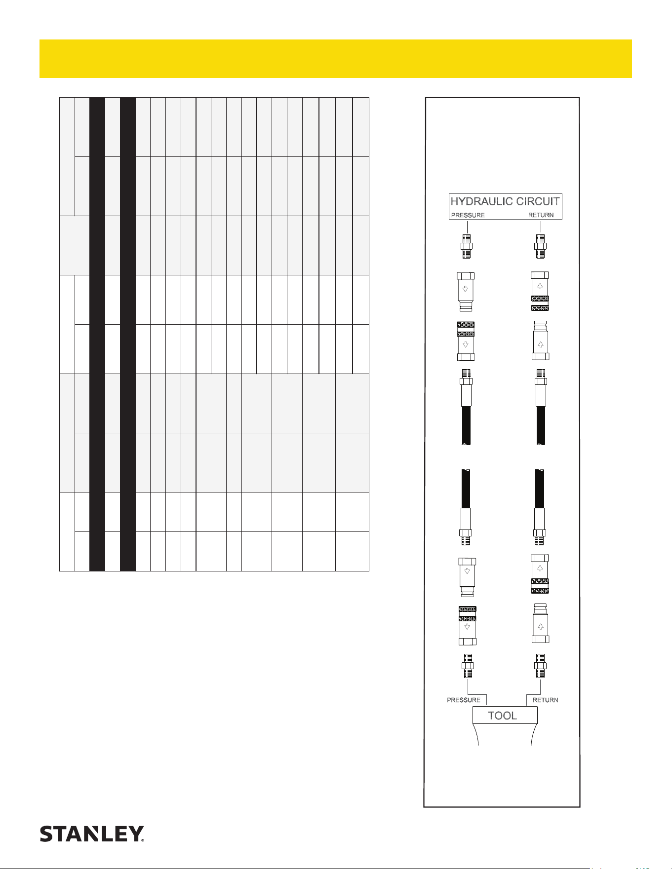
Oil Flow Hose Lengths Inside Diameter
USE
(
Press/Return)
Min. Working Pressure
GPM LPM FEET METERS INCH MM PSI BAR
Certi ed Non-Conductive Hose - Fiber Braid - for Utility Bucket Trucks
4-9 15-34 up to 10 up to 3 3/8 10 Both 2250 155
Conductive Hose - Wire Braid or Fiber Braid -DO NOT USE NEAR ELECTRICAL CONDUCTORS
4-6 15-23 up to 25 up to 7.5 3/8 10 Both 2500 175
4-6 15-23 26-100 7.5-30 1/2 13 Both 2500 175
5-10.5 19-40 up to 50 up to 15 1/2 13 Both 2500 175
5-10.5 19-40 51-100 15-30 5/8 16 Both 2500 175
5-10.5 19-40 100-300 30-90
5/8 16 Pressure 2500 175
3/4 19 Return 2500 175
10-13 38-49 up to 50 up to 15 5/8 16 Both 2500 175
10-13 38-49 51-100 15-30
5/8 16 Pressure 2500 175
3/4 19 Return 2500 175
10-13 38-49 100-200 30-60
3/4 19 Pressure 2500 175
1 25.4 Return 2500 175
13-16 49-60 up to 25 up to 8
5/8 16 Pressure 2500 175
3/4 19 Return 2500 175
13-16 49-60 26-100 8-30
3/4 19 Pressure 2500 175
1 25.4 Return 2500 175
Figure 1. Typical Hose Connections
Tool to Hydraulic Circuit Hose
Recommendations
The chart to the right shows recommended
minimum hose diameters for various
hose lengths based on gallons per minute
(GPM)/liters per minute (LPM). These
recommendations are intended to keep return
line pressure (back pressure) to a minimum
acceptable level to ensure maximum tool
performance.
This chart is intended to be used for hydraulic
tool applications only based on STANLEY tool
operating requirements and should not be
used for any other applications.
All hydraulic hose must have at least a
rated minimum working pressure equal to
the maximum hydraulic system relief valve
setting.
All hydraulic hose must meet or exceed
speci cations as set forth by SAE J517.
PRESSURE
RETURN
<<< FLOW
FLOW >>>
HOSE RECOMMENDATIONS
12 ► CS05/CS06 User Manual
HTMA / EHTMA REQUIREMENTS
TOOL TYPE
HTMA
HYDRAULIC SYSTEM REQUIREMENTS
TYPE I TYPE II TYPE RR TYPE III
Flow range
4-6 GPM
(15-23 LPM)
7-9 GPM
(26-34 LPM)
9-10.5 GPM
(34-40 LPM)
11-13 GPM
(42-49 LPM)
Nominal operating pressure
(At the power supply outlet)
1500 psi
(103 bar)
1500 psi
(103 bar)
1500 psi
(103 bar)
1500 psi
(103 bar)
System relief valve setting
(At the power supply outlet)
2100-2250 psi
(145-155 bar)
2100-2250 psi
(145-155 bar)
2200-2300 psi
(152-159 bar)
2100-2250 psi
(145-155 bar)
Maximum back pressure
(At tool end of the return hose)
250 psi
(17 bar)
250 psi
(17 bar)
250 psi
(17 bar)
250 psi
(17 bar)
Measured at a max uid viscosity of:
(At minimum operating temperature)
400 ssu*
(82 centistokes)
400 ssu*
(82 centistokes)
400 ssu*
(82 centistokes)
400 ssu*
(82 centistokes)
Temperature: Su cient heat rejection capacity to limit
maximum uid temperature to:
(At maximum expected ambient temperature)
140° F
(60° C)
140° F
(60° C)
140° F
(60° C)
140° F
(60° C)
Minimum cooling capacity at a temperature di erence of
between ambient and uid temps
3 hp
(2.24 kW)
40° F
(22° C)
5 hp
(3.73 kW)
40° F
(22° C)
6 hp
(5.22 kW)
40° F
(22° C)
7 hp
(4.47 kW)
40° F
(22° C)
Note: Do not operate the tool at oil temperatures above 140° F (60° C). Operation at higher temperatures can cause operator
discomfort at the tool.
Filter minimum full- ow ltration 25 microns 25 microns 25 microns 25 microns
Sized for ow of at least:
(For cold temp startup and maximum dirt-holding capacity)
30 GPM
(114 LPM)
30 GPM
(114 LPM)
30 GPM
(114 LPM)
30 GPM
(114 LPM)
Hydraulic uid, petroleum based (premium grade, anti-
wear, non-conductive) Viscosity (at minimum and maximum
operating temps)
100-400 ssu
(20-82
centistokes)
100-400 ssu
(20-82
centistokes)
100-400 ssu
(20-82
centistokes)
100-400 ssu
(20-82
centistokes)
Note: When choosing hydraulic uid, the expected oil temperature extremes that will be experienced in service determine the most
suitable temperature viscosity characteristics. Hydraulic uids with a viscosity index over 140 will meet the requirements over a wide
range of operating temperatures.
*SSU = Saybolt Seconds Universal
CLASSIFICATION
EHTMA
HYDRAULIC SYSTEM
REQUIREMENTS
B
C
D
Flow range
3.5-4.3 GPM
(13.5-16.5
LPM)
4.7-5.8 GPM
(18-22 LPM)
7.1-8.7 GPM
(27-33 LPM)
9.5-11.6 GPM
(36-44 LPM)
11.8-14.5 GPM
(45-55 LPM)
Nominal operating pressure
(At the power supply outlet)
1870 psi
(129 bar)
1500 psi
(103 bar)
1500 psi
(103 bar)
1500 psi
(103 bar)
1500 psi
(103 bar)
System relief valve setting
(At the power supply outlet)
2495 psi
(172 bar)
2000 psi
(138 bar)
2000 psi
(138 bar)
2000 psi
(138 bar)
2000 psi
(138 bar)
Note: These are general hydraulic system requirements. See tool speci cation page for tool speci c requirements.
HTMA / EHTMA REQUIREMENTS

CS05/CS06 User Manual ◄ 13
OPERATING PROCEDURES
The following are general wood cut ting procedures and
techniques. Di erences in the terrain, vegetation, and
type of wood will make this infor mation more or less valid
for particu lar areas. For advice on specic woodcutting
problems or techniques for your area, consult your local
STANLEY representative or your county agent. They
can often provide infor mation that will make your work
safer and more productive.
CUTTING TIPS
1. Check the lean of the tree. Tie a weight to a piece
of string about 2 feet long. Hang the weight in your
line of sight. The string is a good vertical line to help
you judge the lean of the tree. The tree should fall
the way it is leaning. Trees that are straight (leaning
no more than 5 degrees) gener ally can be felled in
any direction.
2. Avoid felling across another tree, log, rocks, gully or
ridge. Do not fell straight uphill or down hill. Fell the
tree diagonally to the hill. Consider the wind direction
and velocity. Do not attempt cutting in strong winds.
3. Check the weight distribution. A tree is heavier on
the side with the most limbs. It will try to fall on its
heavy side. Trim a few limbs to “balance” the tree.
4. Clear the work area. You need a clean area all
around the tree for good footing. Get every thing
out of the area where the tree will fall. Do not cut
trees near structures. Because of the danger of
electrocution, use extreme care when cutting trees
near power lines.
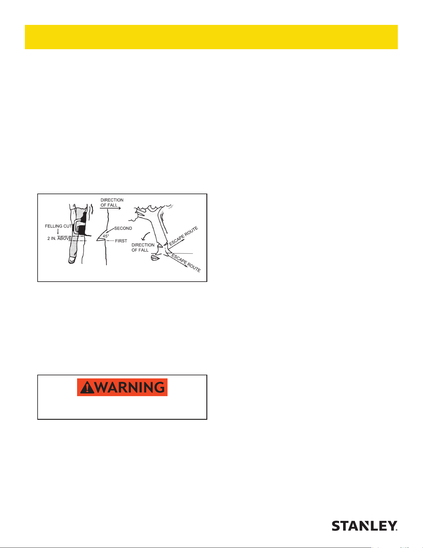
5. Before starting the cut, prepare your escape path.
Make sure the escape path is clear of brush and
branches. The escape path should be at an angle
away from the direction of fall.
6. The saw chain should cut with very little pres sure
PREOPERATION PROCEDURES
CHECK POWER SOURCE
1. Using a calibrated owmeter and pressure gauge,
check that the hydraulic power source develops a
ow of 4-6 gpm/15-23 lpm at 1500-2000 psi/105-
140 bar for the CS05 or a ow of 7-9 gpm/26-34 lpm
at 1000-2000 psi/70-140 bar for the CS06.
2. Make certain that the hydraulic power source is
equipped with a relief valve set to open at 2100 -
2250 psi/145-155 bar.
CONNECT HOSES
1. Wipe all hose couplers with a clean lint-free cloth
before making connections.
2. Connect the hoses from the hydraulic power source
to the tool ttings or quick disconnects. It is good
practice to connect return hoses rst and disconnect
them last to minimize or avoid trapped pressure
within the tool.
3. Observe the arrow on the couplers to ensure that the
ow is in the proper direction. The female coupler on
the tool hose is the inlet (pressure) coupler.
4. Move the hydraulic circuit control valve to the “ON”
position to operate the tool.
NOTE:
If uncoupled hoses are left in the sun, pressure
increase inside the hose may make them dicult to
connect. Whenever possible, connect the free ends
of the hoses together.
SYSTEM SELECTION (OC/CC)
Saws congured with the system selector option require
setup for the system, closed-center (CC) or open-center
(CC), in which it will operate. The selector screw is
located in the bottom end of the valve spool.
1. Determine the system type.
2. For operation in a CC system, turn the selector
screw fully clockwise. When the selector screw
bottoms, CC operation is selected.
3. For operation in an OC system, turn the selector
screw counter-clockwise until meeting resistance
(from the retaining ring). Turn the selector screw
clockwise and then counter-clockwise to be sure
that you are sensing resistance of the retaining ring.
Do not force the selector screw.
To prevent damage to the retaining ring, do not
attempt to force the selector screw counter-clockwise
beyond the point of initial resistance.
OPERATION
14 ► CS05/CS06 User Manual
is being made parallel to the notch cut. Cut until the
saw is about 1 or 2 inches from the notch. Do not cut
through the notch.
NOTE:
The uncut wood between the felling and notch cuts
is called the hinge. The hinge controls the fall of the
tree and should be of uniform thick ness.
6. As the saw nears the back cut, watch the treetop
and the cut for signs of movement. Be alert as
soon as the tree starts to move, turn o the saw,
pull it from the tree and move away quickly on your
escape route.
7. For trees larger than bar length, make two felling
cuts. Cut in as far as the bar will go, move to the other
side and start the second cut in the same manner as
the rst while pivoting the saw to complete the felling
cut.
BUCKING
Bucking is the sawing of a log or fallen tree into smaller
pieces.
1. Observe all safety precautions.
2. Use both hands. Grip the saw rmly.
3. Stand uphill. A log that is cut loose may role downhill.
4. Keep the chain out of the dirt. Dirt will dull the chain.
A dull chain is unsafe.
5. Stand to the left of the saw.
CROSSCUTTING
NOTE:
Before starting to cut through a log try to imagine
what is going to happen. Look out for stresses in the
log and cut through the log in such a manner that
the guide bar will not get pinched.
applied to the handle. If you have to force the saw
to cut or if the cut is not straight, cease cutting
immediately to prevent further saw chain and bar
damage. See the Maintenance and Adjustments
section of the Service Manual for chain replacement
or adjustment procedures.
7. Underwater models require daily preventive
maintenance. See the Maintenance and Adjust-
ments section of the Service Manual for these
mainte nance procedures.
FELLING (CUTTING DOWN A
TREE) (FIGURE 2)
Observe all safety precautions.
Figure 2. Felling a Tree
NOTCHING OR UNDERCUTTING
1. The notching or undercutting cut is made on the side
you want the tree to fall. Place the saw so the hand
guard is close to the tree trunk and the bucking cleat
is dug in.
2. Start the cut horizontally. Pivot the nose of the bar in
last. Cut to about one-quarter of the tree’s diameter.
3.
Watch out for falling limbs.
Make a diagonal cut down to meet the hori zontal cut
and remove the wood from the notch.
FELLING OR BACK CUT
4. The felling or back cut is made on the side opposite
and at least 2 inches above the hori zontal undercut
(the felling cut is made higher as the size of the tree
increases). Place the saw so the hand guard is close
to the tree trunk and the bucking cleat is dug in.
5. Start the cut horizontally. Pivot the bar in until the cut
OPERATION
CS05/CS06 User Manual ◄ 15
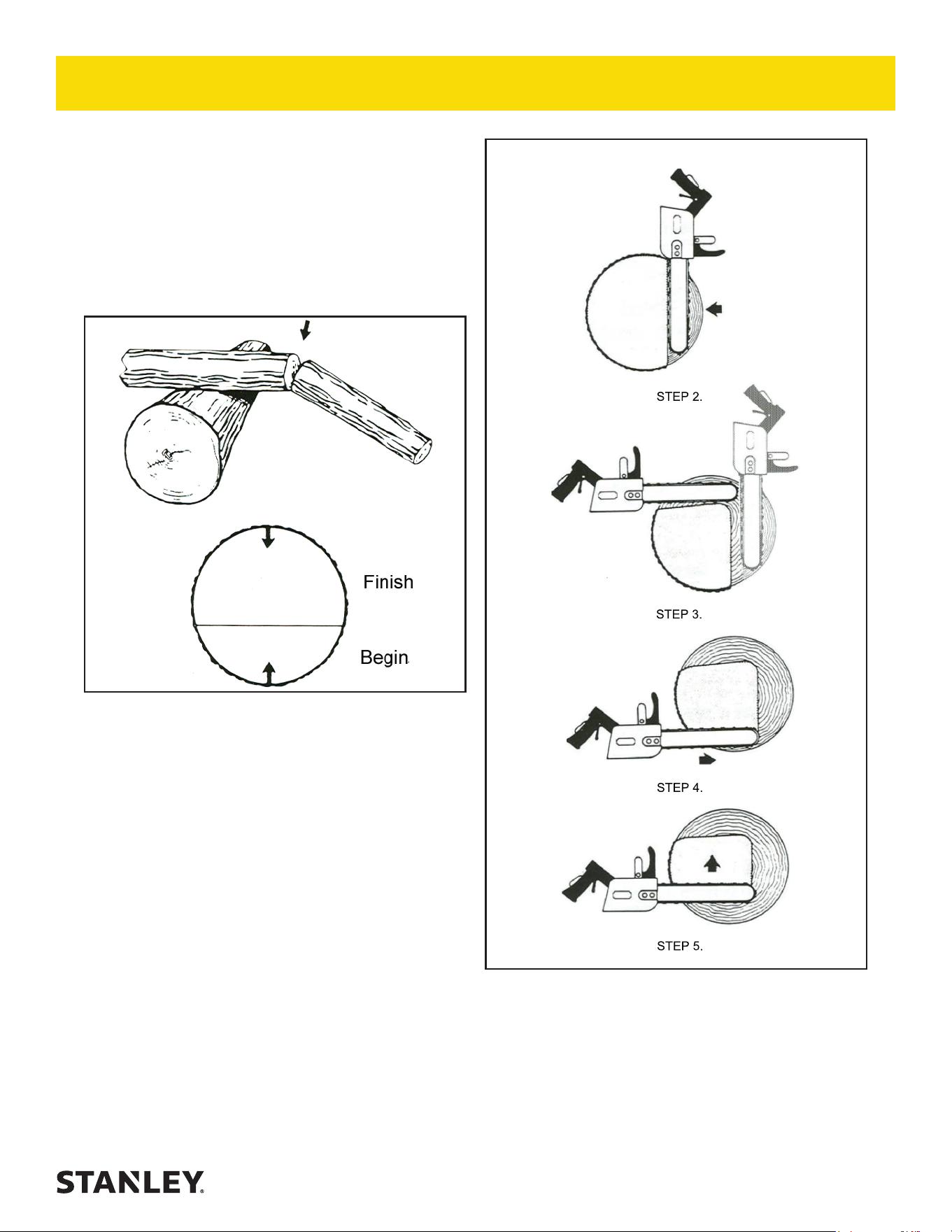
Figure 4. Crosscutting Logs Larger than Bar Length
With Pressure on Top
LOGS WITH PRESSURE ON TOP
(FIGURE 3)
1. Observe all safety precautions.
2. Begin with an upper cut, down from the top. Do not
cut too deeply. A cut of about 1/3 of the log diameter
is enough.
3. Finish with a bottom cut. They should meet.
Figure 3. Crosscutting Logs with Pressure on Top
THICK LOGS LARGER THAN BAR
LENGTH WITH PRESSURE ON TOP
(FIGURE 4)
1. Observe all safety precautions.
2. Begin by cutting on the opposite side of the log.
3. Pull the saw towards you and cut from the top.
4. Cut from the bottom. Make a boring cut if the log is
close to the ground.
5. Finish with a bottom cut.
OPERATION
16 ► CS05/CS06 User Manual
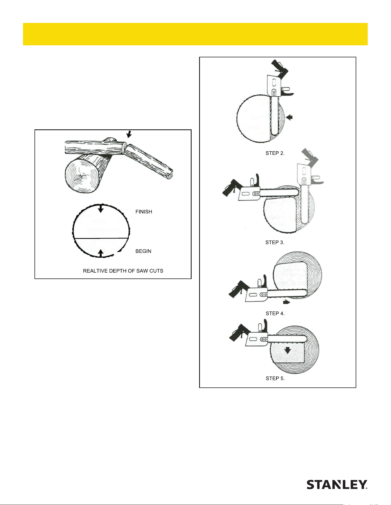
Figure 6. Crosscutting Thick Logs with Pressure on
Bottom
LOGS/LIMBS WITH PRESSURE ON
BOTTOM (FIGURE 5)
1. Observe all safety precautions.
2. Begin with a bottom cut. The depth of the cut should
be about 1/3 of the log diameter.
3. Finish with an upper cut, down from the top. The
saw cuts should meet.
Figure 5. Crosscutting Logs/Limbs with
Pressure on Bottom.
THICK LOGS LARGER THAN BAR
LENGTH WITH PRESSURE ON THE
BOTTOM (FIGURE 6)
1. Observe all safety precautions.
2. Begin by cutting on the opposite side of the log.
3. Pull the saw towards you and cut from the top.
4. Cut from the bottom. Make a boring cut if the log is
close to the ground.
5. Finish with a top cut.
OPERATION

CS05/CS06 User Manual ◄ 17
PRUNING AND DEBRANCHING
1. Observe all safety precautions.
2. Use both hands. Keep a rm grip.
3. Be alert for kickback. Do not allow the tip of the bar
to touch anything while the chain is in motion.
4. Do not cut overhead. Keep the saw below chest
level. The chain is too close to your face in this
position.
COLD WEATHER OPERATION
If the saw is to used during cold weather, preheat the
hydraulic uid at low engine speed. When using the
normally recommended oils, oil should be at or above
50 °F/10 °C (400 ssu/ 82 centistokes) before use.
Damage to the hydraulic system or saw can result from
use with uid that is too viscous or thick.
Cutting frozen wood causes the cutters to wear,
crack and break at the back rivet hole unless proper
precautions are taken. To extend chain life when cutting
in cold weather:
1. Be sure the oiler is working.
2. Keep the chain tensioned and check often.
3. Keep the cutters properly sharpened. Touch up at
least every hour. Never force a dull chain to cut.
4. Clean out the bar groove and keep the oil hole open.
Turn the bar over to equalize wear on the rails.
5. Always install a new sprocket with a new chain.
UNDERWATER MODEL
MAINTENANCE
After each use, the movable portions of the tool that
were exposed to water should be ushed with a water
displacing oil, such as WD40™. Remove water and de-
bris as follows:
1. Spray oil through the tool and displace any remain-
ing water.
2. Spray oil into the On/O trigger slot area
3. Dip or spray the entire tool.
4. Cycle the tool hydraulically several times before
storing away.
OPERATION

18 ► CS05/CS06 User Manual
• Make sure all couplers are wiped clean before
connection.
• The hydraulic circuit control valve must be in
the “OFF” position when coupling or uncoupling
hydraulic tools. Failure to do so may result in damage
to the quick couplers and cause overheating of the
hydraulic system.
• Always store the tool in a clean dry space, safe from
damage or pilferage.
• Make sure the circuit PRESSURE hose (with male
quick disconnect) is connected to the “IN” port. The
circuit RETURN hose (with female quick disconnect)
is connected to the opposite port. Do not reverse
circuit ow. This can cause damage to internal seals.
• Always replace hoses, couplings and other parts
with replacement parts recommended by STANLEY.
Supply hoses must have a minimum working
pressure rating of 2500 psi/172 bar.
In addition to the Safety Precautions found in
this manual, observe the following for equipment
protection and care.
• Do not exceed the rated ow. See
“SPECIFICATIONS” on page 20 for correct ow
rate and model number. Rapid failure of the internal
seals may result.
• Always keep critical tool markings, such as warning
stickers and tags legible.
• Tool repair should be performed by experienced
personnel only.
• Make certain that the recommended relief valves
are installed in the pressure side of the system.
• Do not use the tool for applications for which it was
not intended.
TOOL PROTECTION & CARE

CS05/CS06 User Manual ◄ 19
If symptoms of poor performance develop, the following chart can be used as a guide to correct the problem. When
diagnosing faults in operation of the saw, always make sure the hydraulic power source is supplying the correct
hydraulic ow and pressure to the saw as listed in the table. Use a ow meter known to be accurate. Check the ow
with the hydraulic uid temperature at least 80 °F/27 °C.
PROBLEM CAUSE REMEDY
Cuts slow. Insucient uid ow or low relief
valve setting.
Adjust uid ow to proper gpm. For
optimum performance adjust relief
valve to 2250 psi/155 psi.
Chain dull. Sharpen or replace.
Backpressure too high. Should not exceed 250 psi/17 bar at
8 gpm/30 lpm measured at the end
of the tool operating hoses.
Bar turns color. Insucient oiler ow. Adjust oiler per Service Manual.
Tool does not run. Power unit not functioning. Check power unit for proper ow
and pressure (4 gpm/15 lpm at 1500
psi/104 bar minimum for the CS05
and 7 gpm/26 lpm at 1000 psi/70 bar
for the CS06).
Coupler or hoses blocked. Remove obstruction.
Mechanical failure. Disassemble tool and inspect for
damage.
Tool runs backwards. Pressure and return hoses are
reversed.
Connect for proper ow direction.
Motor shaft rotates clockwise.
On/O trigger is hard to press. Pressure and return hoses are
reversed.
Correct for proper ow direction.
Backpressure too high. Should not exceed 250 psi/17 bar at
8 gpm/30 lpm measured at the end
of the tool operating hoses.
Oil leakage around drive sprocket. Motor shaft seal failure. Replace as required. Make sure that
oil present is not the result of excess
oiler ow.
Oil leakage between rear gear
housing and valve handle assembly.
Motor face seal failure. Replace as required.
Chain continues to move after valve
is shut o.
Chain is too loose. Tighten chain.
Input ow too high. Decrease ow.
TROUBLESHOOTING

20 ► CS05/CS06 User Manual
Capacity
CS05 ..................................................................................................... 12 and 15 inch/30 and 38 cm Cut Lengths
CS06 ......................................................................................... 12, 15 and 20 inch/30, 38 and 51 cm Cut Lengths
Weight (w/o bar) ...................................................................................................................................6.25 lbs/2.8 kg
Length (w/o bar) ................................................................................................................................14 inches/36 cm
Width ...................................................................................................................................................9 inches/23 cm
Pressure
CS05 .............................................................................................................................1500-2000 psi/105-140 bar
CS06 ................................................................................................................................ 1000-2000 psi/26-34 lpm
Optimum Flow
CS05 .................................................................................................................................................. 5 gpm/19 lpm
CS06 .................................................................................................................................................. 8 gpm/30 lpm
Porting ....................................................................................................................................................8 SAE O-ring
Connect Size and Type ....................................................................................................3/8 inch NPT Male Adapter
Hose Whips ............................................................................................................................................................ No
Motor ...............................................................................................................................................................Integral
Kickback Reduction Features
....................Low Kickback Saw Chain, Small Radius Saw Bar, Front Hand Guard, Low Inertia Motor/Drive System
Sound Power Level ....................................................................................................................................... 107 dBA
Sound Pressure Level @ 1 meter ................................................................................................................ 93.1 dBA
Vibration Level ..............................................................................................................................................3.1 (m/s
2
)
ACCESSORIES
Rim Sprocket, .325 P × 7 Tooth ......................................................................................................................... 07629
12-inch Saw Bar ................................................................................................................................................08347
15-inch Saw Bar ................................................................................................................................................07638
20-inch Saw Bar ................................................................................................................................................07639
Saw Chain for 12-inch Bar.................................................................................................................................08348
Saw Chain for 15-inch Bar.................................................................................................................................07641
Saw Chain for 20-inch Bar.................................................................................................................................07642
File Guide with File ............................................................................................................................................ 12363
Flat File .............................................................................................................................................................. 11294
Scrench ............................................................................................................................................................. 11464
SERVICE TOOLS
O-ring Tool Kit .................................................................................................................................................... 04337
Seal Kit ..............................................................................................................................................................07830
SPECIFICATIONS
CS05/CS06 User Manual ◄ 21
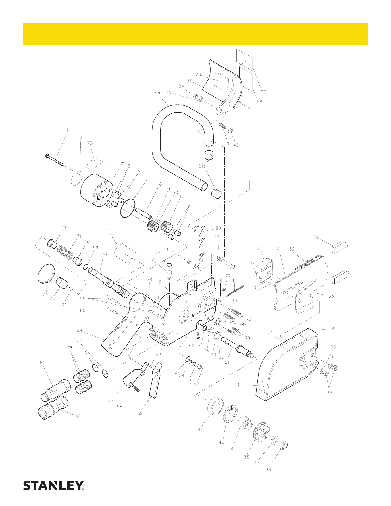
CS05/CS06 PARTS ILLUSTRATION

22 ► CS05/CS06 User Manual
ITEM
NO.
PART
NO. QTY DESCRIPTION
1 00753
09622
8 CAPSCREW
CAPSCREW U/W MODEL
2 74750
74748
1 NAME TAG—CS06
NAME TAG—CS05
3 28323 1 CE DECAL (CE ONLY)
4 07652 1 REAR GEAR HSG ASSY (7–9 GPM)
07834 1 REAR GEAR HSG ASSY (4–6 GPM)
5 00289 2 DOWEL PIN
6 04041 4 BUSHING
7 00020 1 O-RING
8 07612 1 IDLER SHAFT
9 04106
07832
2 DRIVE GEAR (7–9 GPM)
DRIVE GEAR (4–6 GPM)
10 — — NO ITEM
11 00038
00788
1 NUT
NUT U/W MODEL
12 01362 1 O-RING
13 02921 1 AUTOMATIC OILER
14 17784 1 SOUND POWER LEVEL. DECAL
(CE ONLY)
15 06971
07724
1 LOCKNUT
LOCKNUT U/W MODEL
16 07620
07714
1 BAR ADJUSTMENT NUT
BAR ADJUSTMENT NUT U/W MODEL
17 11354 1 OC/CC DECAL (NOT ILLUSTRATED)
18 07632
07723
1 SCREW
SCREW U/W MODEL
19 00144
00230
1 CAPSCREW
CAPSCREW U/W MODEL
20 01116 1 BUCKING CLEAT
21 02649 2 HANDLE BAR RETAINER
22 07611 1 HANDLE BAR
23 02634 3 WASHER
12175 3 WASHER U/W MODEL
24 00429
09277
1 NUT
NUT U/W MODEL
25 07473 1 HAND GUARD
26 13907 1 WARNING DECAL (KICKBACK)
27 12412 1 WARNING DECAL (ELECTRIC)
28 28409 1 COMPOSITE SAFETY DECAL (CE
ONLY)
29 07628
02446
3 CAPSCREW
CAPSCREW U/W MODEL
30 66577 1 CHAIN GUIDE PLATE-INSIDE
31 08347 1 SAW BAR 12 IN.
07638 1 SAW BAR 15 IN.
07639 1 SAW BAR 20 IN.
32 08348 1 SAW CHAIN – 12 IN.
07641 1 SAW CHAIN – 15 IN.
ITEM
NO.
PART
NO. QTY DESCRIPTION
07642 1 SAW CHAIN – 20 IN.
33 66578 1 CHAIN GUIDE PLATE-OUTSIDE
34 80884 1 CHAIN GUARD
35 07631
07722
2 NUT
NUT U/W MODEL
36 00453
00808
1 NUT
NUT U/W MODEL
37 07617 1 WASHER
38 07629 1 RIM SPROCKET
39 07616 1 SPROCKET ADAPTER
40 06635 1 RET RING
41 00335
07720
1 BALL BEARING
BALL BEARING U/W MODEL
42 04746 1 AUTOMATIC OILER DECAL
43 04539 1 WASHER
44 07623 1 CHAIN CATCHER
45 07630 2 STUD
07712 2 STUD U/W MODEL
46 02688
02764
1 CAPSCREW
CAPSCREW U/W MODEL
47 04037 1 SHAFT SEAL
48 07615 1 SEAL BACK-UP WASHER
49 04856 1 RETAINING RING
50 04044 2 NEEDLE ROLLER
51 07613
07710
1 DRIVE SHAFT
DRIVE SHAFT U/W MODEL
52 16070 1 RETAINING RING
53 10536 1 SELECTOR SCREW
54 00026 1 O-RING
55 07627 1 O-RING
56 00072
00875
1 ROLL PIN
ROLL PIN U/W MODEL
57 07603 1 SAFETY CATCH
58 07602
07715
1 SPRING
SPRING U/W MODEL
59 34093 1 TRIGGER CASTING
60 03972 1 COUPLER, FEMALE
61 03973 1 COUPLER, MALE
63 01605 2 O-RING
64 07693
07713
1 VALVE HANDLE ASSY
VALVE HANDLE ASSY U/W MODEL
65 07624
07718
1 ROLL PIN
ROLL PIN U/W MODEL
66 17668
74841
2 ROLL PIN
ROLL PIN U/W MODEL
67 11207 1 CIRCUIT TYPE D DECAL (CE ONLY)
68 10535 1 ON/OFF VALVE SPOOL
69 07626 1 O-RING
CS05/CS06 PARTS LIST

CS05/CS06 User Manual ◄ 23
ITEM
NO.
PART
NO. QTY DESCRIPTION
70 07609 2 SPRING WASHER
71 07610 1 SPRING
72 00190 1 ROLL PIN
73 10537 1 KEEPER
74 07625 1 PLUG BUTTON
75 03786 1 GPM STICKER (7–9 GPM)
03782 1 GPM STICKER (4–6 GPM)
76 05144 1 BAR & CHAIN GUARD
77 00767 1 GREASE FITTING U/W MODEL ONLY
78 00936 2 ADAPTER (COMES WITH ITEM 63)
26414 1 LOCK OUT KIT, SHIPPED INSTALLED
(NOT SHOWN)
03971 1 COUPLER SET
07830 1 SEAL KIT
CS05/CS06 PARTS LIST
24 ► CS05/06 User Manual
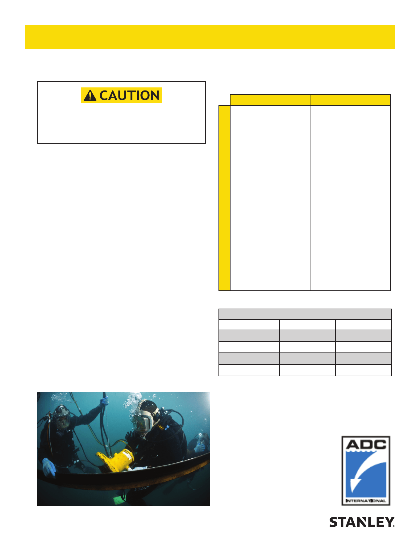
RECOMMENDED HOSE DIAMETERS
DEPTH (FT) 8 GPM 12 GPM
100 5/8” 5/8”
300 3/4” 1”
600 1” 1”
1000 1” 1-1/4”
UNDERWATER MODELS ONLY
Do not use hydraulic tools underwater that are not
designated as an “underwater” model, or this will
result in damage to the tool.
For underwater hydraulic tools the
applications are broken down into four
quadrants depending on type of tool and
method of operation.
The types of tools are percussive and
rotational, each with di erent characteristics
allowing for di erent depth operation. With
percussive tools, the nitrogen accumulator
PSI must counter the increase in ambient
pressure found at lower depths. Since there is
a maximum PSI for percussive tools they are
limited to certain depths. Rotational tools do
not have accumulators and thus are capable
of deeper depths.
The methods are broken into diver operated
or remote operated vehicle (ROV). ROV’s
can reach lower depths and with an onboard
hydraulic power source that is depth
compensated, can operate hydraulic tools at
depths of thousands of feet. ROV operation
is still limited to the tool, for example a
percussive tool has the same depth limitation
whether ROV or diver operated.
OPERATION OVERVIEW
PERCUSSIVE ROTATIONAL
DIVER
Tools: Breakers,
Hammer Drills and
Chipping Hammers
Max Depth: 500’ -
limitations due to
accumulator PSI
max (increase 40
PSI for every 100’)
Tools: Grinders,
Saws, Chain Saws
Max Depth: 1000’
- Reference hose
sizing guide below
ROV
Tools: Breakers,
Hammer Drills and
Chipping Hammers
Max Depth: 500’ -
limitations due to
accumulator PSI
max (increase 40
PSI for every 100’)
Tools: Grinders,
Saws, Chain Saws
Max Depth: 1000’
- Reference hose
sizing guide below
UNDERWATER TOOLS DEPTH GUIDELINE


STANLEY Infrastructure
6430 SE Lake Road
Portland, Oregon 97222 USA
(503) 659-5660 / Fax (503) 652-1780
www.stanleyinfrastructure.com
