Loading ...
Loading ...
Loading ...
9
7. Electricalwork
Caution:
• Beforeinstallingthegrille,makesurethatthejunctionwireisconnected.
• Ifthe grillehassignal receiveror i-Seesensor, thepackof grilleincludes
junctionwire.
Signalreceiver: CN90
3Di-Seesensor: CN5Y
3Di-Seesensormotor:CN4Z
CN5Y
CN90
CN4Z
Fig.7-6
Fig.7-5
Fig.7-3
B
C
D
E
Between ribs
15
Be sure to connect the remote
controllercable(0.3mm,
AWG22)tothelocationsshown
in the diagram.
Secure with a band 4(small)atthe
location shown in the diagram
Secure with a band 4(small)
at the location shown in the
diagram
(Remotecontroller
cableretainer)
Cable strap
12
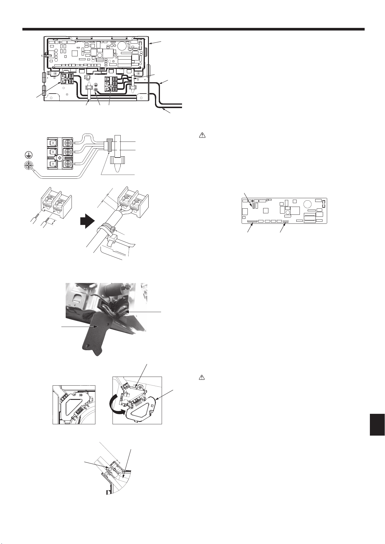
7.2.1.Installingthei-Seesensorandsignalreceiver
Beforeinstallingthegrille,connectthejunctionwiresincludedwiththegrilleacces-
soriesandplacethemintheconnectorbox.
1Removethetwoscrewssecuringthewirecoverofthemainunit,andthenopen
thecover.
2Routethewiresofthei-Seesensorandsignalreceiverthroughthewireinletsin
theelectriccomponentboxasshowninthediagramandaroundthebushingson
thesideofthemainunit.(Fig.7-4)
Whenroutingthewires,opentheclampsecuringthegrillejunctionwire,andthen
securethegrillejunctionwireandthewiresofthei-Seesensorandsignalreceiver
with the clamp.
3Removetheonescrewsecuringtheconnectorboxcover,andthenopenthecover.
(Fig.7-5)
4Placethejunctionwireconnectorintheconnectorbox.
5Installthewirecoverandconnectorboxcover.
Caution:
Wheninstallingthecovers,makesurethatthewiresdonotgetpinched.
Fitthebandsecuringthejunctionwiresbetweentheribsontheconnectorbox
asshowninthediagram.(Fig.7-6)
A Wirecover
B Connectorboxcover
C Connectorbox
D i-Seesensororsignalreceiverleadwire(Grilleaccessory)
E Band
S1 S2 S3
A
Fig.7-4
Fig.7-2
E
B
E
D
C
I
G
F
D
Loading ...
Loading ...
Loading ...