Loading ...
Loading ...
Loading ...
17
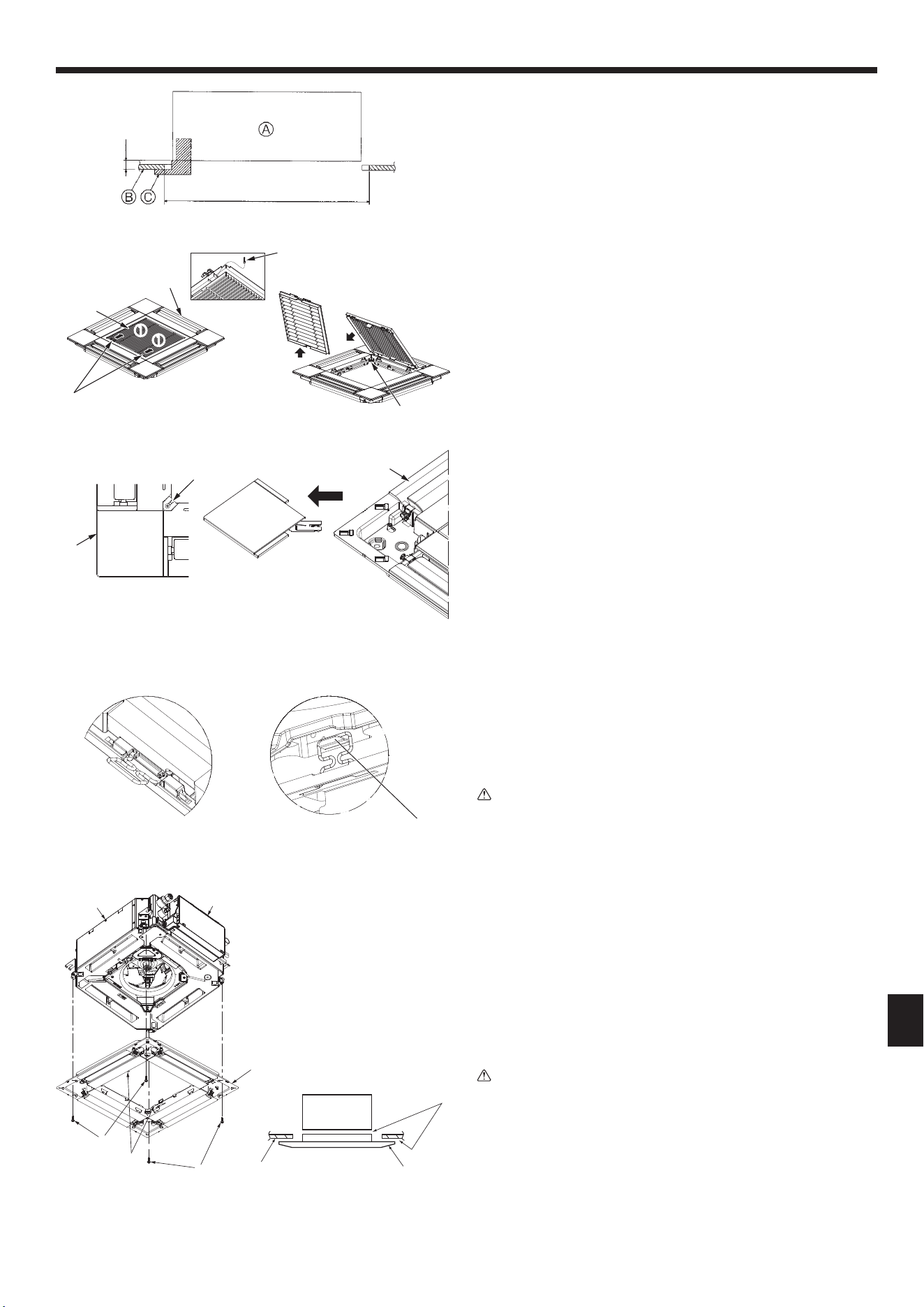
Fig.10-4
10.2.2.Removingthecornerpanel(Fig.10-4)
• Loosenthescrewfromthecornerofthecornerpanel.Slidethecornerpanelas
indicated by the arrow 1toremovethecornerpanel.
A Grille
B Corner panel
C Screw
A
B
1
C
10. Installingthegrille
Fig.10-5
<Hookisintheraisedposition>
Mainunithook
<Grillehook>
10.3. Installingthegrille
• Pleasepayattentionbecausethereisarestrictionintheattachmentpositionofthe
grille.
10.3.1.Temporarilyinstallingthegrille
• Alignthescrewholesinthecornersofthegrillewiththescrewmountingholesin
thecornersofthemainunit,latchthetwohooksonthegrilleontothedrainpan
projectionsonthemainunit,andtemporarilyhangthegrille.(Fig.10-5)
Caution:
Wheninstallingthei-Seesensorandsignalreceiver,placethejunctionwires
intheconnectorboxbeforetemporarilyhangingthegrille.
Referto7.2.1.onpage9toroutethejunctionwires.
Fig.10-7Fig.10-6
10.3.2.Securingthegrille
• Securethegrillebytighteningthefourscrews.(Fig.10-6)
*Makesurethattherearenogapsbetweenthemainunitandthepanelorthepanel
andtheceiling.(Fig.10-7)
A Mainunit
B Electriccomponentbox
C Screwwithwasher(Accessory)
D Grille
E Ceiling
F Makesurethattherearenogaps.
G Temporarily hanging hooks on the panel
Caution:
• WhentighteningthescrewwithcaptivewasherC,tightenitatatorqueof4.8
N·m(4ft·lbs)orless.Neveruseanimpactscrewdriver.
Itmayresultinpartsdamage.
• Aftertighteningthescrew,conrmthatthetwogrillehooks(Fig.10-5)are
latchedontothehooksonthemainunit.
E
D
F
A
10.2. Preparingtoattachthegrille(Fig.10-2)
• Withthegaugesuppliedwiththiskit,adjustandcheckthepositioningoftheunit
relativetotheceiling.Iftheunitisnotproperlypositionedintheceiling,theremay
beairleaks,condensationmayform,ortheup/downvanesmaynotoperatecor-
rectly.
• Makesurethattheopeningintheceilingiswithinthefollowingtolerances:
576 × 576 to 610 ×610(mm),22-11/16×22-11/16to24-1/32× 24-1/32(inch)
• MakesurethatstepAisperformedwithin37to42mm(1-15/32to1-21/32inch).
Damage could result by failing to adhere to this range.
A Mainunit
B Ceiling
C Gauge(Accessory)
D Ceiling opening dimensions
10.2.1.Removingtheintakegrille(Fig.10-3)
• Slidetheleversinthedirectionindicatedbythearrow1 to open the intake grille.
• Unlatchthehookthatsecuresthegrille.
* Do not unlatch the hook for the intake grille.
• Withtheintakegrilleinthe“open”position,removethehingeoftheintakegrille
from the grille as indicated by the arrow 2.
A Intake grille
B Grille
C Intakegrillelevers
D Grille hook
E Holeforthegrille’shook
Fig.10-2
22-11/16to24-1/32
D
E
1
1
2
B
D
A
C
Fig.10-3
A=1-15/32
+3/16
0
(inch)
B
A
D
C
C
G
Loading ...
Loading ...
Loading ...