Loading ...
Loading ...
Loading ...
8
7. Electricalwork
Indoor unit model SLZ
WiringWireNo.
×size(mm
2
)
Indoorunit-Outdoorunit *1 3×AWG16(polar)
Indoorunit-Outdoorunitearth *1 1×Min.AWG16
Indoor unit earth 1×Min.AWG16
Remotecontroller-Indoorunit *2 2×AWG22(Non-polar)
Circuit rating
Indoorunit(Heater)L-N *3 —
Indoorunit-OutdoorunitS1-S2 *3 208/230VAC
Indoorunit-OutdoorunitS2-S3 *3 24VDC
Remotecontroller-Indoorunit *3 12VDC
7.1. Indoorunitpowersuppliedfromoutdoorunit
Thefollowingconnectionpatternsareavailable.
Theoutdoorunitpowersupplypatternsvaryonmodels.
S1
S2
L1
L2
1
2
S1
S2
S3
S3
A
B C
D
E
F
G
GR
A Outdoorunitpowersupply
B Earth leakage breaker
C Wiringcircuitbreakerorisolatingswitch
D Outdoor unit
E Indoorunit/outdoorunitconnectingcables
F Remote controller
G Indoor unit
*1.<For09-18outdoorunitapplication>
Max.45m,148ft
IfAWG13(2.5mm
2
)used,Max.50m,165ft
IfAWG13(2.5mm
2
)usedandS3separated,Max.80m,263ft
*2.Max.500m,1640ft.
(Whenusing2remotecontrollers,themaximumwiringlengthfortheremotecontrollercablesis200m,656ft.)
*3.TheguresareNOTalwaysagainsttheground.
S3terminalhas24VDCagainstS2terminal.HoweverbetweenS3andS1,theseterminalsarenotelectricallyinsulatedbythetransformerorotherdevice.
Notes: 1. Wiringsizemustcomplywiththeapplicablelocalandnationalcode.
2.
Powersupplycordsandindoorunit/outdoorunitconnectingcordsshallnotbelighterthanpolychloroprenesheathedexiblecord.(Design60245IEC57)
3. Installanearthlongerthanothercables.
4. Indoorandoutdoorconnectingwireshavepolarities.Makesuretomatchtheterminalnumber(S1,S2,S3)forcorrectwirings.
5. Wiringforremotecontrollercableshallbeapart(5cm,2inchormore)frompowersourcewiringsothatitisnotinuencedbyelectricnoisefrom
powersourcewiring.
1:1 System
Neversplicethepowercableortheindoor-outdoorconnectioncable,otherwiseitmayresultinasmoke,areorcommunicationfailure.
Warning:
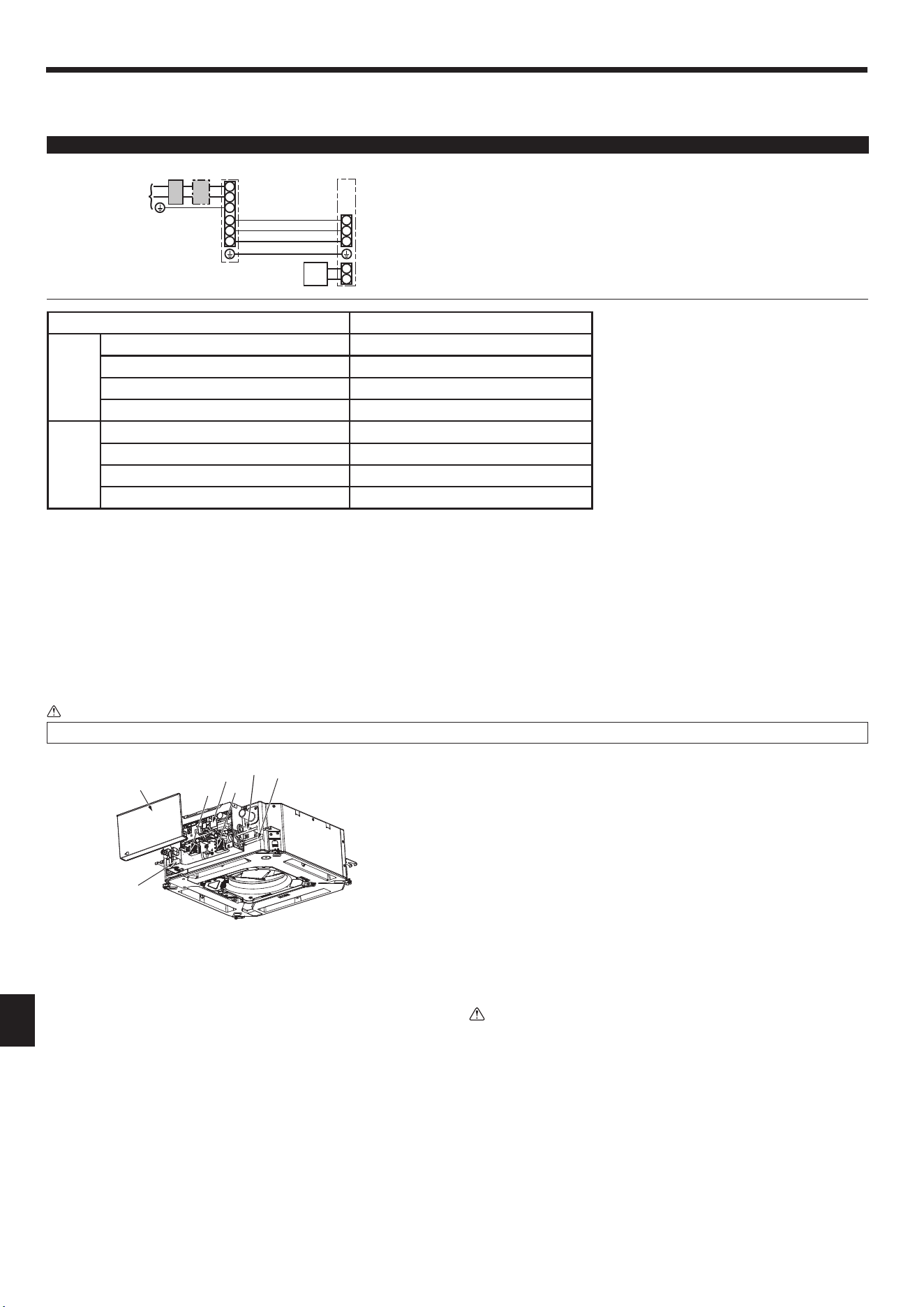
7.2. Indoorunit(Fig.7-1)(Fig.7-2)(Fig.7-3)
Workprocedure
1.Loosenthetwoscrewssecuringtheelectriccomponentcover,andthenslideand
removethecover.
2. Route the wires along the wiring routes and through the wire inlets in the electric
componentbox.
(Procurethepowersupplycordandindoor/outdoorunitconnectingcablelocally.)
3.Securelyconnectthepowersupplycordandtheindoor/outdoorunitconnecting
cable to the terminal block.
4.Securethewireswiththecablestrapsinsidetheelectriccomponentbox.
Secure the wires with cable straps as cushioning components so that no stress is
applied to the connecting sections of the terminal block when tension is generated.
5.Installtheelectriccomponentcover.
Makesurethatthewiresdonotgetpinched.
• Donotallowslackeningoftheterminalscrews.
• Tapeisafxedovertheconduitholeusedforconnectingtheelectricwiring.
Pleaseremovethistapeifmakingaconnectionthroughthehole.
Warning:
• Inserthooktheelectriccomponentcoverintothebentsupportontheelectric
componentboxandattachthecoversecurely.Ifitisattachedincorrectly,it
couldresultinare,electricshockduetodust,water,etc.
• Usethespeciedindoor/outdoorunitconnectingcabletoconnecttheindoor
andoutdoorunitsandxthecabletotheterminalblocksecurelysothatno
stressisappliedtotheconnectingsectionoftheterminalblock.Incomplete
connectionorxingofthecablecouldresultinare.
Fig.7-1
A Electriccomponentcover
B Electriccomponentbox
C EntryforIndoor-Outdoorconnectingcable
D Entry for wired remote controller cable
E Cable clamp
F Indoor/Outdoorunitconnectingterminal
G Wiredremotecontrollerterminal
H Indoor controller
I Earth cable
D
C
BB
H
AA
G
F
Loading ...
Loading ...
Loading ...