Loading ...
Loading ...
Loading ...
7
3
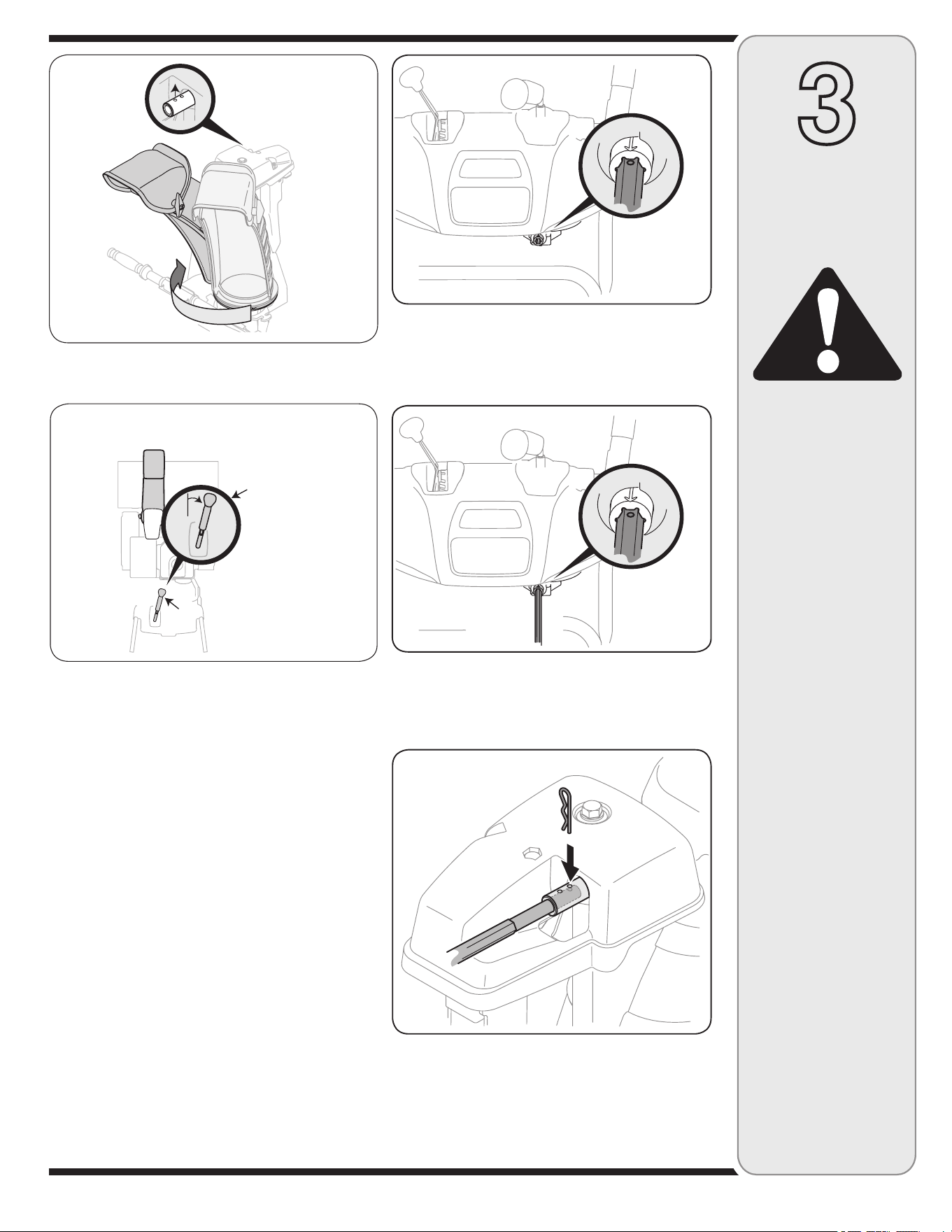
Figure 3-6
CAUTION
Prior to operating
your snow thrower,
refer to Auger Control
Test on page 11.
Read and follow all
instructions care-
fully and perform all
adjustments to verify
your unit is operating
safely and properly.
Setting Up
Your Snow
Thrower
Figure 3-5
Figure 3-7
Figure 3-8
Top
JoystickJoystick
Joystick in the
1 o’clock position.
5. Rotate the joystick to 1 o’clock position (see Figure
3-6) so the silver arrow on the pinion gear faces
upward (see Figure 3-7).
NOTE: The pinion gear is located on the front of the
unit below the control panel.
NOTE: The joystick must be angled slightly to the right
as shown Figure 3-6 and the arrow on the pinion gear
at the top to ensure full chute rotation.
6. Insert the hex end of the rod (hole pointing upward)
into the pinion gear. See Figure 3-8.
7. Secure the round end of the hex rod to the chute
control assembly with the cotter pin removed earlier.
See Figure 3-9.
NOTE: The second hole is used to achieve further en-
gagement of the hex rod into the pinion gear if required,
refer to “Chute Control Rod” in the “Adjustment” section.
8. Finish securing chute rotation assembly to chute
support bracket with wing nut, clevis pin and cotter pin
removed earlier. See Figure 3-2.
Figure 3-9
Loading ...
Loading ...
Loading ...