Loading ...
Loading ...
Loading ...
10
4
Operating
Your Snow
Thrower
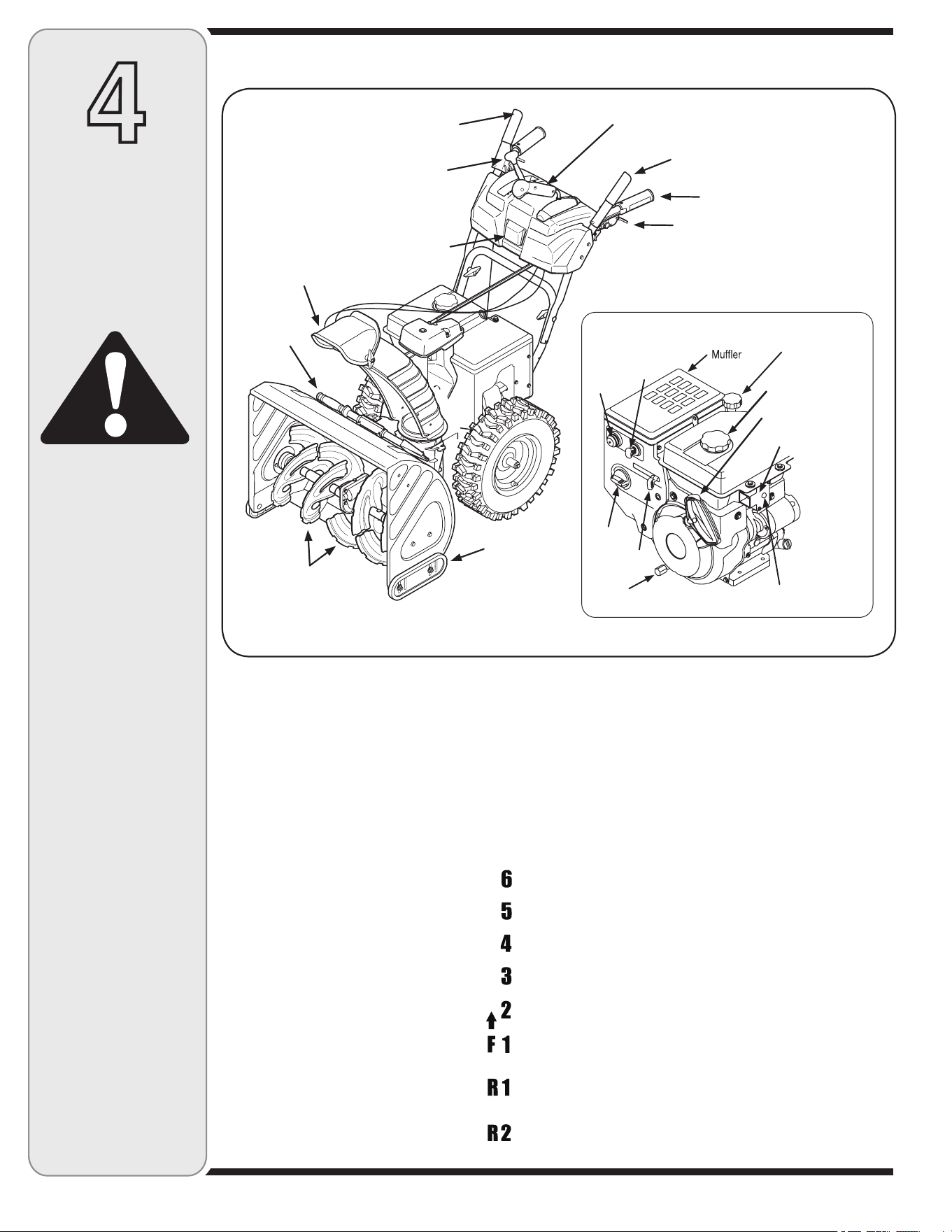
Now that you have set up your snow thrower for opera-
tion, get acquainted with its controls and features. These
are described below and illustrated in Figure 4-1. This
knowledge will allow you to use your new equipment to
its fullest potential.
NOTE: For detailed starting instructions and more
information on all engine controls, refer to the engine
manual packed with your unit.
Shift Lever
The shift lever is located on the right side
of the handle panel. Place the shift lever
into any of eight positions to control the
direction of travel and ground speed.
Forward
Your snow thrower has six forward (F)
speeds, with position number one (1)
being the slowest speed.
Reverse
Your snow thrower has two reverse (R)
speeds, with position number one (1)
being the slower speed.
Know Your Snow Thrower
Choke Control
Activating the choke control closes the choke plate on the
carburetor and aids in starting the engine.
Primer
Depressing the primer forces fuel directly into the engine’s
carburetor to aid in cold-weather starting.
Oil Fill
Engine oil level can be checked and oil added through the
oil fill.
Ignition Key
The ignition key is a safety device. Insert key and snap in
place; do not turn ignition key. Pull the key out halfway to
stop the engine. Remove key when the unit is not in use.
Throttle Control
The throttle control regulates the speed of the engine
and will shut off the engine when moved into the STOP
position.
WARNING
Read, understand,
and follow all instruc-
tions and warnings
on the machine and
in this manual before
operating.
Use extreme care
when handling
gasoline. Gasoline is
extremely flammable
and the vapors are
explosive. Never fuel
the machine indoors
or while the engine
is hot or running.
Extinguish cigarettes,
cigars, pipes and
other sources of
ignition.
Figure 4-1
Augers
Skid Shoe
Clean Out
Tool
Chute Assembly
Drive Control
Shift Lever
4 Way Chute Directional Control
Auger Control
Heated Grip (optional)
Wheel Steering Control
Light
* optional
Engine Controls
Starter Handle
Oil Drain
Oil Filler Cap/
Dipstick
Electric start button*
Electric Switch Box*
Fuel Fill Cap
Primer
Ignition Key
Throttle
Choke
Loading ...
Loading ...
Loading ...